


YAMAHA XV19CTMW(C), XV19CTSW(C), XV19CTW(C), XV19SW(C), XV19W(C) SERVICE MANUALS 1D7
...Yamaha Service Manual
Arranged by CycleHippie
The best Service Manuals have been CycleHippied! Over 30 Years of Powersports Industy Experience goes into the arrangement of the official
Yamaha Factory Service Data.
If you obtained this manual from a source other than
CycleHippie, It may not have been properly CycleHippied!
Go to
CycleHippie eBay Store
www,CycleHippie.com

XV19SW(C)
XV19W(C)
XV19MW(C)
XV19CTSW(C)
XV19CTW(C)
XV19CTMW(C)
SERVICE MANUAL
LIT-11616-20-40 |
1D7-28197-11 |

EAS20050
XV19SW(C)/XV19W(C)/XV19MW(C)/
XV19CTSW(C)/XV19CTW(C)/XV19CTMW(C)
SERVICE MANUAL
©2006 by Yamaha Motor Corporation, U.S.A. First edition, July 2006
All rights reserved.
Any reproduction or unauthorized use without the written permission of Yamaha Motor Corporation, U.S.A.
is expressly prohibited. Printed in U.S.A.
P/N LIT-11616-20-40

EAS20070
NOTICE
This manual was produced by the Yamaha Motor Company, Ltd. primarily for use by Yamaha dealers and their qualified mechanics. It is not possible to include all the knowledge of a mechanic in one manual. Therefore, anyone who uses this book to perform maintenance and repairs on Yamaha vehicles should have a basic understanding of mechanics and the techniques to repair these types of vehicles. Repair and maintenance work attempted by anyone without this knowledge is likely to render the vehicle unsafe and unfit for use.
This model has been designed and manufactured to perform within certain specifications in regard to performance and emissions. Proper service with the correct tools is necessary to ensure that the vehicle will operate as designed. If there is any question about a service procedure, it is imperative that you contact a Yamaha dealer for any service information changes that apply to this model. This policy is intended to provide the customer with the most satisfaction from his vehicle and to conform to federal environmental quality objectives.
Yamaha Motor Company, Ltd. is continually striving to improve all of its models. Modifications and significant changes in specifications or procedures will be forwarded to all authorized Yamaha dealers and will appear in future editions of this manual where applicable.
NOTE:
•This Service Manual contains information regarding periodic maintenance to the emission control system. Please read this material carefully.
•Designs and specifications are subject to change without notice.
EAS20080
IMPORTANT MANUAL INFORMATION
Particularly important information is distinguished in this manual by the following.
 WARNING
CAUTION:
NOTE:
The Safety Alert Symbol means ATTENTION! BECOME ALERT! YOUR SAFETY IS INVOLVED!
Failure to follow WARNING instructions could result in severe injury or death to the vehicle operator, a bystander or a person checking or repairing the vehicle.
A CAUTION indicates special precautions that must be taken to avoid damage to the vehicle.
A NOTE provides key information to make procedures easier or clearer.
EAS20090
HOW TO USE THIS MANUAL
This manual is intended as a handy, easy-to-read reference book for the mechanic. Comprehensive explanations of all installation, removal, disassembly, assembly, repair and check procedures are laid out with the individual steps in sequential order.
•The manual is divided into chapters and each chapter is divided into sections. The current section title is shown at the top of each page “1”.
•Sub-section titles “2” appear in smaller print than the section title.
•To help identify parts and clarify procedure steps, there are exploded diagrams “3” at the start of each removal and disassembly section.
•Numbers “4” are given in the order of the jobs in the exploded diagram. A number indicates a disassembly step.
•Symbols “5” indicate parts to be lubricated or replaced. Refer to “SYMBOLS”.
•A job instruction chart “6” accompanies the exploded diagram, providing the order of jobs, names of parts, notes in jobs, etc.
•Jobs “7” requiring more information (such as special tools and technical data) are described sequentially.

EAS20100
SYMBOLS
The following symbols are used in this manual for easier understanding.
NOTE:
The following symbols are not relevant to every vehicle.
1 |
2 |
3 |
|
||||
|
|
|
|
|
|
|
|
|
|
|
|
|
|
|
|
|
|
|
|
|
|
|
|
|
|
|
|
|
|
|
|
4 |
5 |
6 |
|
|
T |
|
|
. |
|
|
R |
7 |
8 |
|
|
|
|
|
|
|
|
|
|
|
|
|
|
|
|
|
|
|
|
|
|
|
|
|
|
|
|
|
|
|
|
|
|
|
|
|
|
|
|
|
|
|
|
|
|
|
|
|
|
|
|
|
|
|
|
|
|
|
|
|
|
|
|
|
|
|
|
|
|
|
|
|
|
|
|
|
|
|
|
|
|
|
|
|
|
9 |
|
|
|
10 |
|
|
|
11 |
|
|
||||||
|
|
|
|
|
|
|
|
|
|
|
|
|
|
|
|
|
|
|
E |
|
|
|
|
G |
|
|
|
|
M |
||||
12 |
|
|
|
13 |
|
|
|
14 |
|
|
||||||
|
|
B |
|
|
|
|
LS |
|
|
|
|
M |
||||
|
|
|
|
|
|
|
|
|
|
|
|
|||||
15 |
|
|
|
|
|
|
|
|
|
16 |
|
|
||||
|
|
|
|
|
|
|
|
|
|
|
|
|
|
|
|
|
LT New
1.Serviceable with engine mounted
2.Filling fluid
3.Lubricant
4.Special tool
5.Tightening torque
6.Wear limit, clearance
7.Engine speed
8.Electrical data
9.Engine oil
10.Gear oil
11.Molybdenum-disulfide oil
12.Wheel-bearing grease
13.Lithium-soap-based grease
14.Molybdenum-disulfide grease
15.Apply locking agent (LOCTITE®)
16.Replace the part

EAS20110
TABLE OF CONTENTS
GENERAL INFORMATION |
1 |
|
|
SPECIFICATIONS |
2 |
|
|
PERIODIC CHECKS AND ADJUSTMENTS 3
CHASSIS
ENGINE
FUEL SYSTEM
ELECTRICAL SYSTEM
TROUBLESHOOTING
4
5
6
7
8


GENERAL INFORMATION
IDENTIFICATION ............................................................................................ |
1-1 |
|
|
|
VEHICLE IDENTIFICATION NUMBER |
1-1 |
|
|
|
1 |
||||
MODEL LABEL ......................................................................................... |
1-1 |
|
||
FEATURES |
1-2 |
|
||
|
|
|||
OUTLINE OF THE FI SYSTEM |
1-2 |
|
|
|
|
|
|||
FI SYSTEM ............................................................................................... |
1-3 |
|
|
|
INSTRUMENT FUNCTIONS..................................................................... |
1-4 |
|
|
|
IMPORTANT INFORMATION ......................................................................... |
1-8 |
|
|
|
PREPARATION FOR REMOVAL AND DISASSEMBLY .......................... |
1-8 |
|
|
|
REPLACEMENT PARTS .......................................................................... |
1-8 |
|
|
|
GASKETS, OIL SEALS AND O-RINGS .................................................... |
1-8 |
|
|
|
LOCK WASHERS/PLATES AND COTTER PINS..................................... |
1-8 |
|
|
|
BEARINGS AND OIL SEALS.................................................................... |
1-9 |
|
|
|
CIRCLIPS.................................................................................................. |
1-9 |
|
|
|
CHECKING THE CONNECTIONS................................................................ |
1-10 |
|
|
|
SPECIAL TOOLS.......................................................................................... |
1-11 |
|
|
IDENTIFICATION
EAS20130
IDENTIFICATION
EAS20140
VEHICLE IDENTIFICATION NUMBER
The vehicle identification number “1” is stamped into the right side of the steering head pipe.
1
EAS20150
MODEL LABEL
The model label “1” is affixed to the frame under the rider seat. This information will be needed to order spare parts.
1
1-1
FEATURES
EAS20170
FEATURES
ET1D71017
OUTLINE OF THE FI SYSTEM
The main function of a fuel supply system is to provide fuel to the combustion chamber at the optimum air-fuel ratio in accordance with the engine operating conditions and the atmospheric temperature. In the conventional carburetor system, the air-fuel ratio of the mixture that is supplied to the combustion chamber is created by the volume of the intake air and the fuel that is metered by the jet used in the respective carburetor.
Despite the same volume of intake air, the fuel volume requirement varies by the engine operating conditions, such as acceleration, deceleration, or operating under a heavy load. Carburetors that meter the fuel through the use of jets have been provided with various auxiliary devices, so that an optimum airfuel ratio can be achieved to accommodate the constant changes in the operating conditions of the engine.
As the requirements for the engine to deliver more performance and cleaner exhaust gases increase, it becomes necessary to control the air-fuel ratio in a more precise and finely tuned manner. To accommodate this need, this model has adopted an electronically controlled fuel injection (FI) system, in place of the conventional carburetor system. This system can achieve an optimum air-fuel ratio required by the engine at all times by using a microprocessor that regulates the fuel injection volume according to the engine operating conditions detected by various sensors.
The adoption of the FI system has resulted in a highly precise fuel supply, improved engine response, better fuel economy, and reduced exhaust emissions.
1 |
2 |
|
3 |
4 |
5 6 7 8 |
|
9 10 |
11 |
12 |
||||||||||||||
|
|
|
|
|
|
|
|
|
|
|
|
|
|
|
|
|
|
|
|
|
|
|
|
|
|
|
|
|
|
|
|
|
|
|
|
|
|
|
|
|
|
|
|
|
|
|
|
|
|
|
|
|
|
|
|
|
|
|
|
|
|
|
|
|
|
|
|
|
|
|
|
|
|
|
|
|
|
|
|
|
|
|
|
|
|
|
|
|
|
|
|
|
|
|
|
|
|
|
|
|
|
|
|
|
|
|
|
|
|
|
|
|
|
|
|
|
|
|
|
|
|
|
|
|
|
|
|
|
|
|
|
|
|
|
|
|
|
|
|
|
|
|
|
|
|
|
|
|
|
|
|
|
|
|
|
|
|
|
|
|
|
|
|
|
|
|
|
|
|
|
|
|
|
|
|
|
|
|
|
|
|
|
|
|
|
|
|
|
|
|
|
|
|
|
|
|
|
|
|
|
|
|
|
|
|
|
|
|
|
|
|
|
|
|
|
|
|
|
|
|
|
|
|
|
|
|
|
|
|
|
|
|
|
|
|
|
|
|
|
|
|
|
|
|
|
|
|
|
|
|
|
|
|
|
|
|
|
|
|
|
|
|
|
|
|
|
|
|
|
|
|
|
|
|
|
|
|
|
|
|
|
|
|
|
|
|
|
|
|
|
|
|
|
|
|
|
|
|
|
|
|
|
|
|
|
|
|
|
|
|
|
|
|
|
|
|
|
|
|
|
|
|
|
|
|
|
|
|
|
|
|
|
|
|
|
|
|
|
|
|
|
|
|
|
|
|
|
|
|
|
|
|
|
|
|
|
|
|
|
|
|
|
|
|
|
|
|
|
|
|
|
|
|
|
|
|
|
|
|
|
|
|
|
|
|
|
|
|
|
|
|
|
|
|
|
|
|
|
|
|
|
|
|
|
|
|
|
|
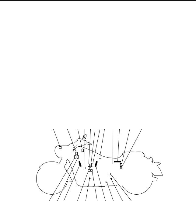
21 |
20 16 |
19 |
18 |
17 |
16 15 |
14 |
13 |
1. |
Air temperature sensor |
|
|
|
|
15. Lean angle sensor |
||
2. |
ISC (idle speed control) unit |
|
|
|
16. Spark plug |
|||
3. |
Cylinder-#2 intake air pressure sensor |
|
|
17. Injector #1 |
||||
4. |
Engine temperature sensor |
|
|
|
18. Crankshaft position sensor |
|||
5. |
Cylinder-#1 right ignition coil |
|
|
|
19. Injector #2 |
|||
6. |
Throttle position sensor |
|
|
|
|
20. Cylinder-#2 right ignition coil |
||
7. |
Cylinder-#1 left ignition coil |
|
|
|
21. Cylinder-#2 left ignition coil |
|||
8.Cylinder-#1 intake air pressure sensor
9.Fuel pump
10.ECU (electronic control unit)
11.Relay unit (fuel pump relay)
12.EXUP servo motor
13.Speed sensor
14.O2 sensor
1-2
FEATURES
ET1D71018
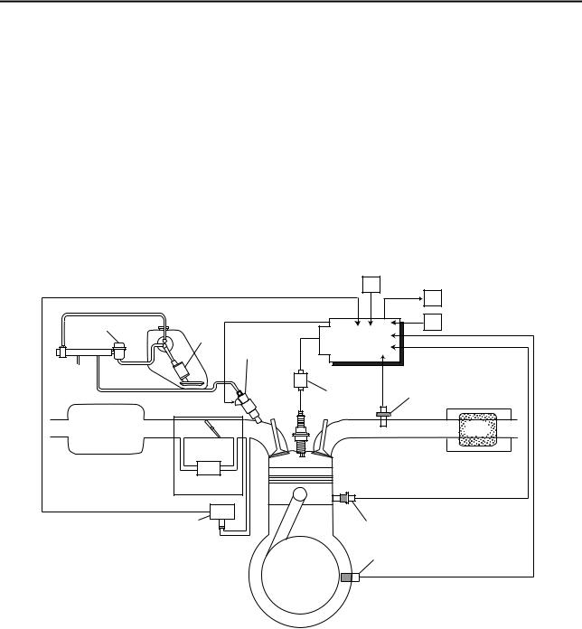
FI SYSTEM
The fuel pump delivers fuel to the fuel injector via the fuel filter. The pressure regulator maintains the fuel pressure that is applied to the fuel injector at only 392 kPa (3.92 kg/cm², 55.7 psi). Accordingly, when the energizing signal from the ECU energizes the fuel injector, the fuel passage opens, causing the fuel to be injected into the intake manifold only during the time the passage remains open. Therefore, the longer the length of time the fuel injector is energized (injection duration), the greater the volume of fuel that is supplied. Conversely, the shorter the length of time the fuel injector is energized (injection duration), the lesser the volume of fuel that is supplied.
The injection duration and the injection timing are controlled by the ECU. Signals that are input from the throttle position sensor, crankshaft position sensor, intake air pressure sensor, air temperature sensor, engine temperature sensor, speed sensor and O2 sensor enable the ECU to determine the injection duration. The injection timing is determined through the signals from the crankshaft position sensor. As a result, the volume of fuel that is required by the engine can be supplied at all times in accordance with the driving conditions.
Illustration is for reference only.
|
|
|
6 |
|
|
|
|
7 |
|
1 |
2 |
C |
8 |
|
A |
5 |
|||
3 |
||||
#2 #1 |
|
|
||
|
|
|
||
|
|
4 |
9 |
|
15 |
|
|
10 |
|
|
B |
|
|
|
|
|
14 |
|
|
|
13 |
|
11 |
|
|
|
|
12 |
1.Pressure regulator
2.Fuel pump
3.Fuel injector
4.Ignition coil
5.ECU (electronic control unit)
6.Air temperature sensor
7.ISC (idle speed control) unit
8.Throttle position sensor
9.O2 sensor
10.Catalytic converter
11.Engine temperature sensor
12.Crankshaft position sensor
13.Intake air pressure sensor
14.Throttle body
15.Air filter case
A.Fuel system
B.Air system
C.Control system
1-3
FEATURES
ET1D71036
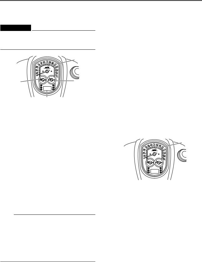
INSTRUMENT FUNCTIONS
Multi-function meter unit
EW1D71008
 WARNING
Be sure to stop the vehicle before making any setting changes to the multi-function meter unit.
1
4 |
2 |
3
1.Speedometer
2.Fuel gauge
3.Odometer/tripmeter/fuel reserve tripmeter/clock
4.Tachometer
The multi-function meter unit is equipped with the following:
•a speedometer (which shows the riding speed)
•a tachometer (which shows the engine speed)
•a fuel gauge
•an odometer (which shows the total distance traveled)
•two tripmeters (which show the distance traveled since they were last set to zero)
•a fuel reserve tripmeter (which shows the distance traveled on the fuel reserve)
•a clock
•a self-diagnosis device
•a brightness control mode
NOTE:
•Be sure to turn the key to “ON” before using the “SELECT” and “RESET” switches, except for setting the brightness control mode.
•To switch the odometer, the tripmeters and the fuel reserve tripmeter displays between kilometers and miles, press the “SELECT” switch for at least two seconds. (For USA and California only)
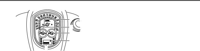
1.“SELECT” switch
2.“RESET” switch
Speedometer
1
1. Speedometer
The speedometer shows the riding speed. When the key is turned to “ON”, the speedometer needle will sweep once across the speed range and then return to zero in order to test the electrical circuit.
1-4
, XV19CTSW(C), XV19CTW(C), XV19SW(C), XV19W(C) SERVICE MANUALS 1D7")
FEATURES
Tachometer
1
2
1.Tachometer
2.Tachometer red zone
The electric tachometer allows the rider to monitor the engine speed and keep it within the ideal power range.
When the key is turned to “ON”, the tachometer needle will sweep once across the r/min range and then return to zero r/min in order to test the electrical circuit.
EC1D71017
CAUTION:
Do not operate the engine in the tachometer red zone.
Red zone: 5000 r/min and above
Fuel gauge
1
1. Fuel gauge
The fuel gauge indicates the amount of fuel in the fuel tank. The needle moves towards “E” (Empty) as the fuel level decreases. When the needle reaches “E”, approximately 3.0 L (0.79 US gal) (0.66 Imp.gal) remain in the fuel tank. If this occurs, refuel as soon as possible.
When the key is turned to “ON”, the fuel gauge needle will sweep once across the fuel level range and then return to the current amount in order to test the electrical circuit.
NOTE:
•Do not allow the fuel tank to empty itself completely.
•The fuel gauge does not indicate the correct fuel level for the first 5 km/h (3 mi/h) after refueling.
Odometer, tripmeter, and clock modes
1 |
1.Odometer/tripmeter/fuel reserve tripmeter/clock
Push the “SELECT” switch to switch the display between the odometer mode “ODO”, the tripmeter modes “TRIP 1” and “TRIP 2” and the clock mode in the following order:
ODO → TRIP 1 → TRIP 2 → Clock → ODO If the fuel level warning light comes on, the odometer display will automatically change to the fuel reserve tripmeter mode “F-TRIP” and start counting the distance traveled from that
point. In that case, push the “SELECT” switch to switch the display between the various tripmeter, odometer, and clock modes in the following order:
F-TRIP → TRIP 1 → TRIP 2 → Clock → ODO → F-TRIP
To reset a tripmeter, select it by pushing the “SELECT” switch, and then push the “RESET” switch for at least one second. If you do not reset the fuel reserve tripmeter manually, it will reset itself automatically, and the display will return to the prior mode after refueling and traveling 5 km (3 mi).
Clock mode
1. Clock
1-5

FEATURES
To set the clock:
1.Push the “SELECT” switch to change the display to the clock mode.
2.Push the “SELECT” and “RESET” switches together for at least two seconds.
3.When the hour digits start flashing, push the “RESET” switch to set the hours.
4.Push the “SELECT” switch, and the minute digits will start flashing.
5.Push the “RESET” switch to set the minutes.
6.Push the “SELECT” switch and then release it to start the clock.
Self-diagnosis device
This model is equipped with a self-diagnosis device for various electrical circuits.
If any of those circuits are defective, the engine trouble warning light will come on, and then the odometer/tripmeter/clock display will indicate a two-digit error code (e.g., 12, 13, 14).
If the odometer/tripmeter/clock display indicates any error codes, note the code number, and then check the vehicle. Refer to “FUEL INJECTION SYSTEM” on page 7-27.
EC1D71018
CAUTION:
If the display indicates an error code, the vehicle should be checked as soon as possible in order to avoid engine damage.
Brightness control mode
Select the brightness control mode as follows.
1.Turn the key to “OFF”.
2.Push and hold the “SELECT” switch.
3.Turn the key to “ON”, and then release the “SELECT” switch after five seconds.
Item number “1” is displayed.
1
2
3
1.Multi-function meter unit panel
2.Item number
3.Brightness level
4.Adjust the multi-function meter unit panel brightness level by pushing the “RESET” switch.
5.Push the “SELECT” switch to select the LCD. Item number “2” is displayed.
Adjust the LCD brightness level by pushing the “RESET” switch.
1
3
4
5
2
1.Multi-function meter unit panel
2.LCD
3.Speedometer needle
4.Tachometer needle
5.Fuel gauge needle
The brightness can be adjusted for the following:
•the multi-function meter unit panel (item number “1”)
•the LCD (item number “2”)
•the speedometer, tachometer, and the fuel gauge needles (item number “3”)
1

 2
2
3
1.LCD
2.Item number
3.Brightness level
6.Push the “SELECT” switch to select the speedometer, tachometer, and the fuel gauge needles.
Item number “3” is displayed.
Adjust the brightness level of the speedometer, tachometer, and the fuel gauge needles by pushing the “RESET” switch.
1-6
FEATURES
1
2
3
4
5
1.Speedometer needle
2.Tachometer needle
3.Fuel gauge needle
4.Item number
5.Brightness level
7.Push the “SELECT” switch.
The odometer/tripmeter/clock display will return to the prior mode.
1-7

IMPORTANT INFORMATION
EAS20180
IMPORTANT INFORMATION
EAS20190
PREPARATION FOR REMOVAL AND DISASSEMBLY
1.Before removal and disassembly, remove all dirt, mud, dust and foreign material.
2.Use only the proper tools and cleaning equipment.
Refer to “SPECIAL TOOLS” on page 1-11.
3.When disassembling, always keep mated parts together. This includes gears, cylinders, pistons and other parts that have been “mated” through normal wear. Mated parts must always be reused or replaced as an assembly.
4.During disassembly, clean all of the parts and place them in trays in the order of disassembly. This will speed up assembly and allow for the correct installation of all parts.
5.Keep all parts away from any source of fire.
EAS20200
REPLACEMENT PARTS
Use only genuine Yamaha parts for all replacements. Use oil and grease recommended by Yamaha for all lubrication jobs. Other brands may be similar in function and appearance, but inferior in quality.
EAS20210
GASKETS, OIL SEALS AND O-RINGS
1.When overhauling the engine, replace all gaskets, seals and O-rings. All gasket surfaces, oil seal lips and O-rings must be cleaned.
2.During reassembly, properly oil all mating parts and bearings and lubricate the oil seal lips with grease.
1.Oil
2.Lip
3.Spring
4.Grease
EAS20220
LOCK WASHERS/PLATES AND COTTER PINS
After removal, replace all lock washers/plates “1” and cotter pins. After the bolt or nut has been tightened to specification, bend the lock tabs along a flat of the bolt or nut.
1-8

IMPORTANT INFORMATION
EAS20230
BEARINGS AND OIL SEALS
Install bearings and oil seals so that the manufacturer’s marks or numbers are visible. When installing oil seals “1”, lubricate the oil seal lips with a light coat of lithium-soap-based grease.
Oil bearings liberally when installing, if appropriate.
ECA13300
CAUTION:
Do not spin the bearing with compressed air because this will damage the bearing surfaces.
EAS20240
CIRCLIPS
Before reassembly, check all circlips carefully and replace damaged or distorted circlips. Always replace piston pin clips after one use.
When installing a circlip “1”, make sure the sharp-edged corner “2” is positioned opposite the thrust “3” that the circlip receives.
1-9

CHECKING THE CONNECTIONS
EAS20250
CHECKING THE CONNECTIONS
Check the leads, couplers, and connectors for stains, rust, moisture, etc.
1.Disconnect:
•Lead
•Coupler
•Connector
2.Check:
•Lead
•Coupler
•Connector
Moisture → Dry with an air blower. Rust/stains → Connect and disconnect several times.
3.Check:
•All connections
Loose connection → Connect properly.
NOTE:
If the pin “1” on the terminal is flattened, bend it up.
4.Connect:
•Lead
•Coupler
•Connector
NOTE:
Make sure all connections are tight.
5.Check:
•Continuity
(with the pocket tester)
Pocket tester 90890-03112
Analog pocket tester YU-03112-C
NOTE:
•If there is no continuity, clean the terminals.
•When checking the wire harness, perform steps (1) to (3).
•As a quick remedy, use a contact revitalizer available at most part stores.
1-10
SPECIAL TOOLS
EAS20260
SPECIAL TOOLS
The following special tools are necessary for complete and accurate tune-up and assembly. Use only the appropriate special tools as this will help prevent damage caused by the use of inappropriate tools or improvised techniques. Special tools, part numbers or both may differ depending on the country.
When placing an order, refer to the list provided below to avoid any mistakes.
NOTE:
•For U.S.A. and Canada, use part number starting with “YM-”, “YU-”, or “ACC-”.
•For others, use part number starting with “90890-”.
Tool name/Tool No. |
Illustration |
Reference |
|
pages |
|||
|
|
||
|
|
|
|
Pocket tester |
|
1-10, 5-79, |
|
90890-03112 |
|
7-73, 7-74, |
|
Analog pocket tester |
|
7-75, 7-79, |
|
YU-03112-C |
|
7-80, 7-81, |
|
|
|
7-82, 7-83, |
|
|
|
7-84, 7-85, |
|
|
|
7-86, 7-87, |
|
|
|
7-88, 7-89, |
|
|
|
7-90, 7-91 |
|
|
|
|
|
Thickness gauge |
|
3-6, 5-61 |
|
90890-03180 |
|
|
|
Feeler gauge set |
|
|
|
YU-26900-9 |
|
|
|
|
|
|
|
Tappet adjusting tool (4 mm) |
|
3-6, 3-7 |
|
90890-04133 |
|
|
|
Valve adjustment wrench 3 mm & 4 mm |
|
|
|
YM-08035-A |
|
|
Vacuum gauge |
3-7 |
90890-03094 |
|
Carburetor synchronizer |
|
YU-44456 |
|
|
YU-44456 |
1-11

|
|
SPECIAL TOOLS |
|
|
|
|
|
|
|
|
|
Tool name/Tool No. |
Illustration |
|
Reference |
|
pages |
||
|
|
|
|
|
|
|
|
Timing light |
|
|
3-10 |
90890-03141 |
|
|
|
Inductive clamp timing light |
|
|
|
YU-03141 |
|
|
|
|
|
|
|
Oil filter wrench |
|
|
3-12 |
90890-01426 |
|
|
|
YU-38411 |
|
|
|
|
|
|
|
Belt tension gauge |
|
|
3-24 |
90890-03170 |
|
|
|
Rear drive belt tension gauge |
|
|
|
YM-03170 |
|
|
|
|
|
|
|
Steering nut wrench |
|
|
3-26, 4-71 |
90890-01403 |
|
|
|
Spanner wrench |
|
|
|
YU-33975 |
|
|
|
|
|
|
|
Damper rod holder |
|
|
4-64, 4-66 |
90890-01460 |
|
|
|
|
|
|
|
T-handle |
|
|
4-64, 4-66 |
90890-01326 |
|
|
|
T-handle 3/8" drive 60 cm long |
|
|
|
YM-01326 |
|
|
|
|
|
|
|
Fork seal driver |
|
|
4-66, 4-67 |
90890-01442 |
|
|
|
Adjustable fork seal driver (36–46 mm) |
|
|
|
YM-01442 |
|
|
|
|
|
|
|
Pivot shaft wrench |
|
|
5-12 |
90890-01485 |
|
|
|
Frame mount insert wrench |
|
|
|
YM-01485 |
|
|
|
|
|
|
|
Valve spring compressor |
|
|
5-39, 5-44 |
90890-04019 |
|
|
|
YM-04019 |
|
|
|
|
|
|
|
1-12
|
|
SPECIAL TOOLS |
|
|
|
|
|
|
|
|
|
Tool name/Tool No. |
Illustration |
Reference |
|
pages |
|||
|
|
||
|
|
|
|
Valve guide remover (ø6) |
|
5-40 |
|
90890-04064 |
|
|
|
Valve guide remover (6.0 mm) |
|
|
|
YM-04064-A |
|
|
|
|
|
|
|
Valve guide installer (ø6) |
|
5-40 |
|
90890-04065 |
|
|
|
Valve guide installer (6.0 mm) |
|
|
|
YM-04065-A |
|
|
|
|
|
|
|
Valve guide reamer (ø6) |
|
5-40 |
|
90890-04066 |
|
|
|
Valve guide reamer (6.0 mm) |
|
|
|
YM-04066 |
|
|
|
|
|
|
|
Piston pin puller set |
|
5-46 |
|
90890-01304 |
|
|
|
Piston pin puller |
|
|
|
YU-01304 |
|
|
|
|
YU-01304 |
|
Universal clutch holder |
5-60, 5-65 |
90890-04086 |
|
YM-91042 |
|
Sheave holder |
5-60, 5-64, |
90890-01701 |
5-74, 5-75 |
Primary clutch holder |
|
YS-01880-A |
|
|
|
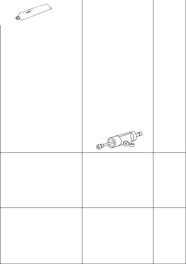
Yamaha bond No. 1215 |
5-66, 5-76, |
90890-85505 |
5-93 |
(Three Bond No.1215®) |
|
1-13

|
|
SPECIAL TOOLS |
|
Tool name/Tool No. |
Illustration |
Reference |
|
pages |
|||
|
|
||
Rotor puller |
|
5-74 |
|
90890-01080 |
|
|
|
Stator rotor puller |
|
|
|
YM-01080-A |
|
|
|
Vacuum/pressure pump gauge set |
|
6-12 |
|
90890-06756 |
|
|
|
Pressure gauge |
|
6-12 |
|
90890-03153 |
|
|
|
Fuel pressure adapter |
|
6-12 |
|
90890-03176 |
|
|
|
YM-03176 |
|
|
|
Digital circuit tester |
|
6-12 |
|
90890-03174 |
|
|
|
Model 88 Multimeter with tachometer |
|
|
|
YU-A1927 |
|
|
|
Ignition checker |
|
7-83 |
|
90890-06754 |
|
|
|
Opama pet-4000 spark checker |
|
|
|
YM-34487 |
|
|
1-14

SPECIAL TOOLS
1-15

SPECIFICATIONS
GENERAL SPECIFICATIONS ........................................................................ |
2-1 |
|
ENGINE SPECIFICATIONS............................................................................ |
2-2 |
|
CHASSIS SPECIFICATIONS........................................................................ |
2-10 |
|
|
|
|
ELECTRICAL SPECIFICATIONS |
2-13 |
2 |
|
||
TIGHTENING TORQUES.............................................................................. |
2-16 |
|
.........................GENERAL TIGHTENING TORQUE SPECIFICATIONS |
2-16 |
|
ENGINE TIGHTENING TORQUES......................................................... |
2-17 |
|
CHASSIS TIGHTENING TORQUES....................................................... |
2-22 |
|
LUBRICATION POINTS AND LUBRICANT TYPES .................................... |
2-27 |
|
ENGINE .................................................................................................. |
2-27 |
|
CHASSIS ................................................................................................ |
2-29 |
|
LUBRICATION SYSTEM CHART AND DIAGRAMS ................................... |
2-31 |
|
ENGINE OIL LUBRICATION CHART ..................................................... |
2-31 |
|
LUBRICATION DIAGRAMS .................................................................... |
2-33 |
|
CABLE ROUTING......................................................................................... |
2-45 |
|
|
GENERAL SPECIFICATIONS |
|
|
EAS20280 |
|
GENERAL SPECIFICATIONS |
|
|
|
Model |
|
Model |
XV19SW 1D74 (USA) |
|
XV19SW 1D76 (CDN) |
|
XV19SWC 1D75 (California) |
|
XV19W 4D45 (USA) |
|
XV19W 4D47 (CDN) |
|
XV19WC 4D46 (California) |
|
XV19MW 4D54 (USA) |
|
XV19MW 4D56 (CDN) |
|
XV19MWC 4D55 (California) |
|
XV19CTSW 2C54 (USA) |
|
XV19CTSW 2C56 (CDN) |
|
XV19CTSWC 2C55 (California) |
|
XV19CTW 4P04 (USA) |
|
XV19CTW 4P06 (CDN) |
|
XV19CTWC 4P05 (California) |
|
XV19CTMW 4P14 (USA) |
|
XV19CTMW 4P16 (CDN) |
|
XV19CTMWC 4P15 (California) |
|
|
Dimensions |
|
Overall length |
2580 mm (101.6 in) |
Overall width |
1100 mm (43.3 in) |
Overall height |
XV19S(C)/XV19(C)/XV19M(C): |
|
1100 mm (43.3 in) |
|
XV19CTS(C)/XV19CT(C)/XV19CTM(C): |
|
1515 mm (59.6 in) |
Seat height |
735 mm (28.9 in) |
Wheelbase |
1715 mm (67.5 in) |
Ground clearance |
155 mm (6.10 in) |
Minimum turning radius |
3480 mm (137.0 in) |
|
|
Weight |
|
With oil and fuel |
XV19S(C)/XV19(C)/XV19M(C): |
|
340.0 kg (750 lb) |
|
XV19CTS(C)/XV19CT(C)/XV19CTM(C): |
|
364.0 kg (802 lb) |
Maximum load |
XV19S(C)/XV19(C)/XV19M(C): |
|
210 kg (463 lb) |
|
XV19CTS(C)/XV19CT(C)/XV19CTM(C): |
|
186 kg (410 lb) |
2-1
|
ENGINE SPECIFICATIONS |
|
|
EAS20290 |
|
ENGINE SPECIFICATIONS |
|
|
|
Engine |
|
Engine type |
Air cooled 4-stroke, OHV |
Displacement |
1854.0 cm³ |
Cylinder arrangement |
V-type 2-cylinder |
Bore × stroke |
100.0 × 118.0 mm (3.94 × 4.65 in) |
Compression ratio |
9.48 :1 |
Starting system |
Electric starter |
|
|
Fuel |
|
Recommended fuel |
Premium unleaded gasoline only |
Fuel tank capacity |
17.0 L (4.49 US gal) (3.74 Imp.gal) |
Fuel reserve amount |
3.0 L (0.79 US gal) (0.66 Imp.gal) |
|
|
Engine oil |
|
Lubrication system |
Dry sump |
Type |
YAMALUBE 4 (20W40) or SAE20W40 |
Recommended engine oil grade |
API service SG type or higher, JASO standard |
|
MA |
Engine oil quantity |
|
Total amount |
5.20 L (5.50 US qt) (4.58 Imp.qt) |
Engine |
3.2 L (3.38 US qt) (2.82 Imp.qt) |
Oil tank |
2.0 L (2.11 US qt) (1.76 Imp.qt) |
Without oil filter cartridge replacement |
4.10 L (4.33 US qt) (3.61 Imp.qt) |
With oil filter cartridge replacement |
4.90 L (5.18 US qt) (4.31 Imp.qt) |
Oil pressure (hot) |
60.0 kPa/900 r/min (8.7 psi/900 r/min) (0.60 |
|
kgf/cm²/900 r/min) |
|
|
Transfer gear oil |
|
Type |
SAE80 API GL-4 Hypoid gear oil |
Quantity (disassembled) |
0.60 L (0.63 US qt) (0.53 Imp.qt) |
Quantity |
0.55 L (0.58 US qt) (0.48 Imp.qt) |
|
|
Oil filter |
|
Oil filter type |
Cartridge (paper) |
|
|
Oil pump |
|
Oil pump type |
Trochoid |
Inner-rotor-to-outer-rotor-tip clearance |
Less than 0.12 mm (0.0047 in) |
Limit |
0.20 mm (0.0079 in) |
Outer-rotor-to-oil-pump-housing clearance |
0.09–0.19 mm (0.0035–0.0075 in) |
Limit |
0.26 mm (0.0102 in) |
Oil-pump-housing-to-inner-and-outer-rotor |
|
clearance |
0.06–0.13 mm (0.0024–0.0051 in) |
Limit |
0.20 mm (0.0079 in) |
Bypass valve opening pressure |
80.0–120.0 kPa (11.6–17.4 psi) (0.80–1.20 |
|
kgf/cm²) |
Relief valve operating pressure |
600.0 kPa (87.0 psi) (6.00 kgf/cm²) |
|
|
Transfer gear oil pump |
|
Oil pump type |
Trochoid |
2-2

|
|
|
|
|
ENGINE SPECIFICATIONS |
|
|
|
|
|
|
Inner-rotor-to-outer-rotor-tip clearance |
Less than 0.12 mm (0.0047 in) |
||||
Limit |
0.20 mm (0.0079 in) |
||||
Outer-rotor-to-oil-pump-housing clearance |
0.10–0.15 mm (0.0039–0.0059 in) |
||||
Limit |
0.22 mm (0.0087 in) |
||||
Oil-pump-housing-to-inner-and-outer-rotor |
|
||||
clearance |
0.04–0.09 mm (0.0016–0.0035 in) |
||||
Limit |
0.160 mm (0.0063 in) |
||||
|
|
|
|
|
|
Spark plug (s) |
|
||||
Manufacturer/model |
NGK/DPR8EA-9 |
||||
Manufacturer/model |
DENSO/X24EPR-U9 |
||||
Spark plug gap |
0.8–0.9 mm (0.031–0.035 in) |
||||
|
|
|
|
|
|
Cylinder head |
|
||||
Volume |
80.90–84.90 cm³ (4.94–5.18 cu.in) |
||||
Warpage limit |
0.03 mm (0.0012 in) |
||||
|
|
|
|
|
|
|
|
|
|
|
|
|
|
|
|
|
|
|
|
|
|
|
|
|
|
|
|
|
|
Camshaft |
|
Drive system |
Gear drive |
Crankcase hole inside diameter |
25.000–25.021 mm (0.9843–0.9851 in) |
Camshaft journal diameter (crankcase side) |
24.957–24.980 mm (0.9826–0.9835 in) |
Camshaft to crankcase clearance |
0.020–0.064 mm (0.0008–0.0025 in) |
Camshaft cover hole inside diameter |
28.000–28.021 mm (1.1024–1.1032 in) |
Camshaft journal diameter (camshaft cover side) |
27.957–27.980 mm (1.1007–1.1016 in) |
Camshaft to camshaft cover clearance |
0.020–0.064 mm (0.0008–0.0025 in) |
Camshaft lobe dimensions |
|
Intake A |
42.532–42.632 mm (1.6745–1.6784 in) |
Limit |
42.432 mm (1.6705 in) |
Intake B |
35.950–36.050 mm (1.4154–1.4193 in) |
Limit |
35.850 mm (1.4114 in) |
Exhaust A |
42.530–42.630 mm (1.6744–1.6783 in) (cylinder |
|
#1) |
|
42.531–42.631 mm (1.6744–1.6784 in) (cylinder |
|
#2) |
Limit |
42.430 mm (1.6705 in) (cylinder #1) |
|
42.431 mm (1.6705 in) (cylinder #2) |
Exhaust B |
35.950–36.050 mm (1.4154–1.4193 in) |
Limit |
35.850 mm (1.4114 in) |
2-3

|
|
|
|
|
|
|
|
ENGINE SPECIFICATIONS |
|
|
|
|
|
|
|
|
|
|
|
|
|
|
|
|
|
|
|
|
|
|
|
|
|
|
|
|
|
|
|
|
A |
|
||
|
|
|
|
|
|
|
|
|
|
|
|
|
|
|
|
|
|
|
|
B |
|
|
|
|
||
|
|
|
|
|
|
|||
|
|
|
|
|
|
|
|
|
Rocker arm/rocker arm shaft |
|
|||||||
Rocker arm inside diameter |
18.000–18.018 mm (0.7087–0.7094 in) |
|||||||
Limit |
18.036 mm (0.7101 in) |
|||||||
Rocker arm shaft outside diameter |
17.976–17.991 mm (0.7077–0.7083 in) |
|||||||
Rocker-arm-to-rocker-arm-shaft clearance |
0.009–0.042 mm (0.0004–0.0017 in) |
|||||||
Limit |
0.080 mm (0.0032 in) |
|||||||
|
|
|
|
|
|
|
|
|
Valve, valve seat, valve guide |
|
|||||||
Valve clearance (cold) |
|
|||||||
Intake |
0.00–0.04 mm (0.0000–0.0016 in) |
|||||||
Exhaust |
0.00–0.04 mm (0.0000–0.0016 in) |
|||||||
Valve dimensions |
|
|||||||
Valve head diameter A (intake) |
35.90–36.10 mm (1.4134–1.4213 in) |
|||||||
Valve head diameter A (exhaust) |
30.90–31.10 mm (1.2165–1.2244 in) |
|||||||
|
|
|
A |
|
||||
Valve seat width C (intake) |
1.10–1.30 mm (0.0433–0.0512 in) |
|||||||
Limit |
2.0 mm (0.08 in) |
|||||||
Valve seat width C (exhaust) |
1.10–1.30 mm (0.0433–0.0512 in) |
|||||||
Limit |
2.0 mm (0.08 in) |
|||||||
|
|
|
|
C |
|
|||
Valve margin thickness D (intake) |
1.15–1.45 mm (0.0453–0.0571 in) |
|||||||
Limit |
0.4 mm (0.02 in) |
|||||||
Valve margin thickness D (exhaust) |
1.15–1.45 mm (0.0453–0.0571 in) |
|||||||
Limit |
0.4 mm (0.02 in) |
|||||||
|
|
|
|
|
D |
|
||
Valve stem diameter (intake) |
5.975–5.990 mm (0.2352–0.2358 in) |
|||||||
Limit |
5.945 mm (0.2341 in) |
|||||||
Valve stem diameter (exhaust) |
5.960–5.975 mm (0.2346–0.2352 in) |
|||||||
Limit |
5.920 mm (0.2331 in) |
|||||||
Valve guide inside diameter (intake) |
6.000–6.012 mm (0.2362–0.2367 in) |
|||||||
Limit |
6.050 mm (0.2382 in) |
|||||||
2-4
 Loading...