


XS650H 1978
Yamaha XS650H 1978, XS650H 1979, XS650G 1978, XS650G 1979, XS650SH 1978 Supplementary Service Manual
...
INDEX
This manual has been combined with previous
service manuals to provide complete service
information for: XS650H/SH.
Please read and give special consideration to
the “NOTICE” on the preceding page for your
safety.
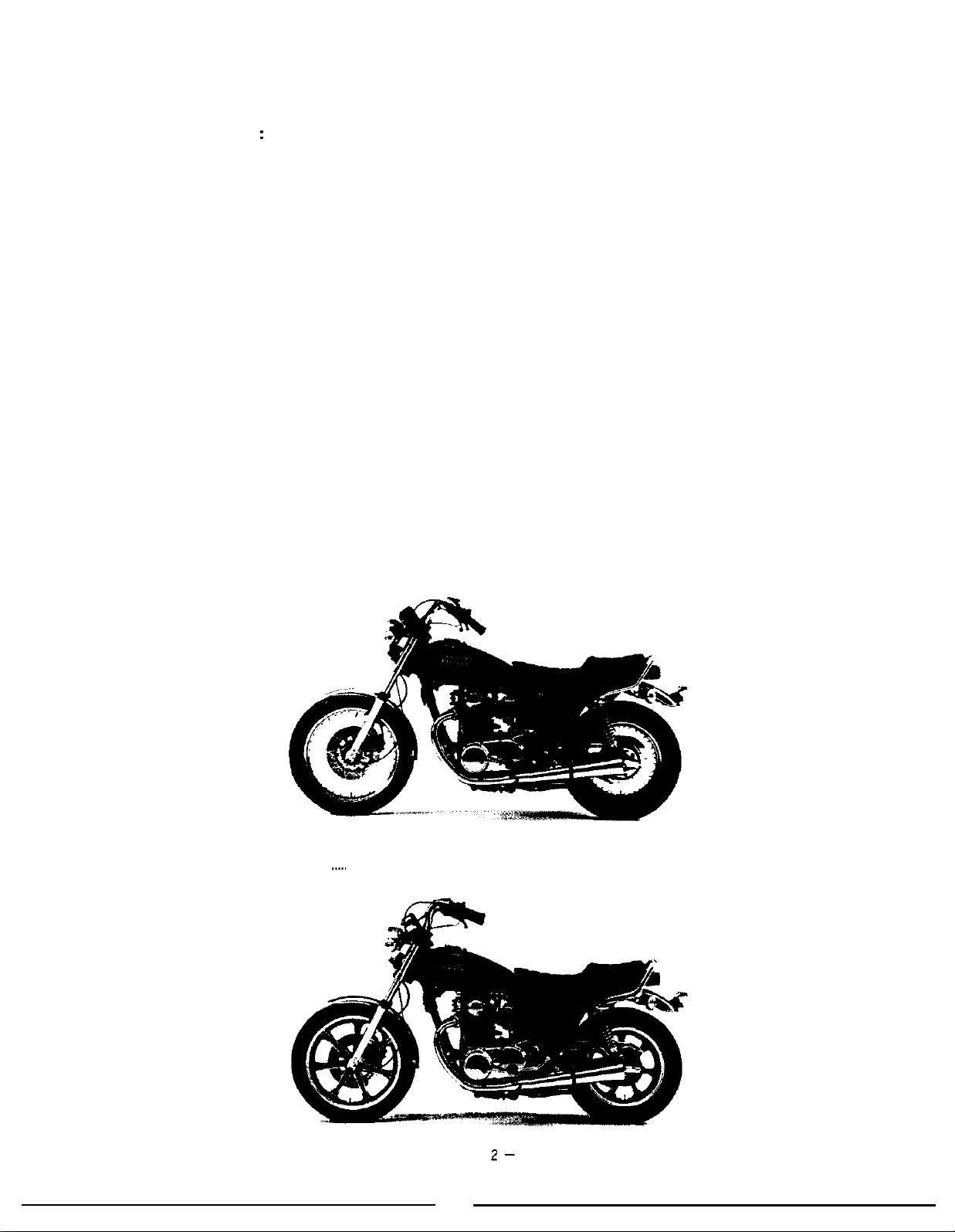
XS650H/SH
XS650
MODELS 1978-80
SUPPLEMENT
FOREWORD
This Supplementary Service Manual has been prepared to introduce new
service and new data for the XS650H/XS650SH. For complete information
on service procedure, it is necessary to use this Supplementary Service
Manual together with following manuals:
’
XS650E Service Manual (LIT-11616-00-76)
!’XS650SE Supplementary Service Manual (LIT-11616-01-08)
XS650SF/2F Supplementary Service Manual (LIT-11616-01-65)
XS650G/SG
NOTE:
This Supplementary Service Manual contains information regarding periodic
maintenance to the emission control system for the
Please read this material carefully.
Supplementary Service Manual (LIT-1 1616-01-75)
SERVICE DEPT.
INTERNATIONAL DIVISION
YAMAHA MOTOR CO., LTD.
XS650H/XS650SH.
NOTICE
This manual was written by the Yamaha Motor Company primarily for use
by Yamaha dealers and their qualified mechanics.
an entire mechanic’s education into one manual, so it is assumed that
persons using this book to perform maintenance and repairs on Yamaha
motorcycles have a basic understanding of the mechanical concepts and
procedures inherent to motorcycle repair technology. Without such know-
ledge, attempted repairs or service to this model may render it unfit for use
and/or unsafe.
It is not possible to put
I
1
This model has been designed and manufactured to perform within certain
specifications in regard to performance and emissions. Proper service with
the correct tools is necessary to ensure that the motorcycle will operate as
designed.
that you contact a Yamaha dealer before continuing. Before attempting any
service, check with your Yamaha dealer for any service information changes
that apply to this model: This policy is intended to provide the customer
with the most satisfaction from his motorcycle and to conform with federal
environmental quality objectives.
Yamaha Motor Company, Ltd. is continually striving to further improve all
models manufactured by Yamaha. Modifications and significant changes in
specifications or procedures will be forwarded to all Authorized Yamaha
dealers and will, where applicable, appear in future editions of this manual.
If there is any question about a service procedure it is imperative
I -
Particularly important information is distinguished in this manual by the
following notations:
NOTE
:
A NOTE provides key information to make procedures easier
or clearer.
CAUTION: A CAUTION indicates special procedure that must be fol-
lowed to avoid damage to the motorcycle.
WARNING:
A WARNING indicates special procedures that must be followed to avoid injury to a motorcycle operator or person
inspecting or repairing the motorcycle.
Starting Serial Number
XS650HH
XS650SHH
. . . . . . . . . . . . .
. . . . . . . .
4N9-000101
..__.
4M4-000101
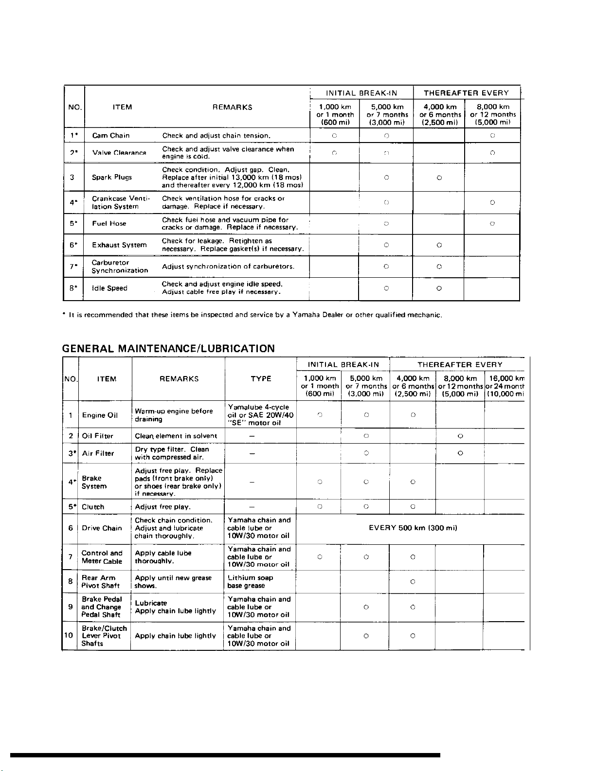
MAINTENANCE AND LUBRICATION CHART
PERIODIC MAINTENANCE EMISSION CONTROL SYSTEM
-3

t
c
c
*ENGINE
A. IGNITION TIMING
The ignition system is modified for easier
maintenance. Thus, the following “ignition
timing check” should be changed,
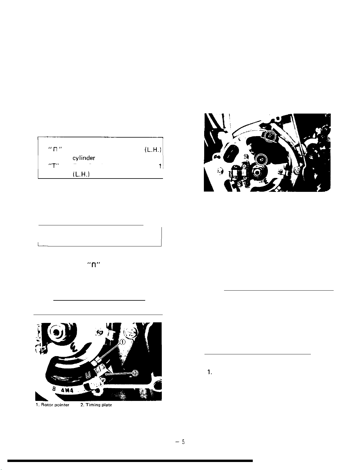
Ignition timing check
1. Ignition timing is checked with a timing
light by observing the position of the
rotor pointer and the marks stamped on
the timing plate.
The timing plate is marked as follows.
“ll”
Firing range for No. 1
(L.H.)
B. PICK-UP COIL ASSEMBLY
The method of mounting the pick-up coil
assembly is changed for easier service work.
Thus, the followings “Pick-up coil assembly
removal” and “Pick-up coil assembly reinstallation” should be changed.
Pick-up coil assembly removal
Remove the pick-up coil securing screws and
remove the pick-up coil
assembly.
“T” Top Dead Center for No.
fL.H.1
cylinder
2. Connect the timing light to the left
cylinder spark plug lead wire.
3. Start the engine and keep the engine
speed as specified. Use a tachometer to
check the engine speed.
Specified engine speed:
1,200 r/min
_
L
4.
The rotor pointer should be within
the limits of
”
fl
”
on the timing plate.
If it exceeds the limits or does not
steady, check the timing plate for tightness and/or ignition system for damage.
NOTE:
Ignition timing is not adjustable.
1,
Pick-up coil assembly reinstallation
Install the pick-up coil assembly on to the
stator
assembly.
C. FUEL LEVEL
The carburetor is furnished with a drain screw
to provide easy access to service work. Thus,
the following
“Fuel level measurement”
should be added.
Fuel level measurement
NOTE:
Before checking the fuel level, note the following:
1.
Place the motorcycle on a level surface.
2. Adjust the motorcycle position by placing a suitable stand or a garage jack
under the engine so that the carburetor
is positioned vertically.
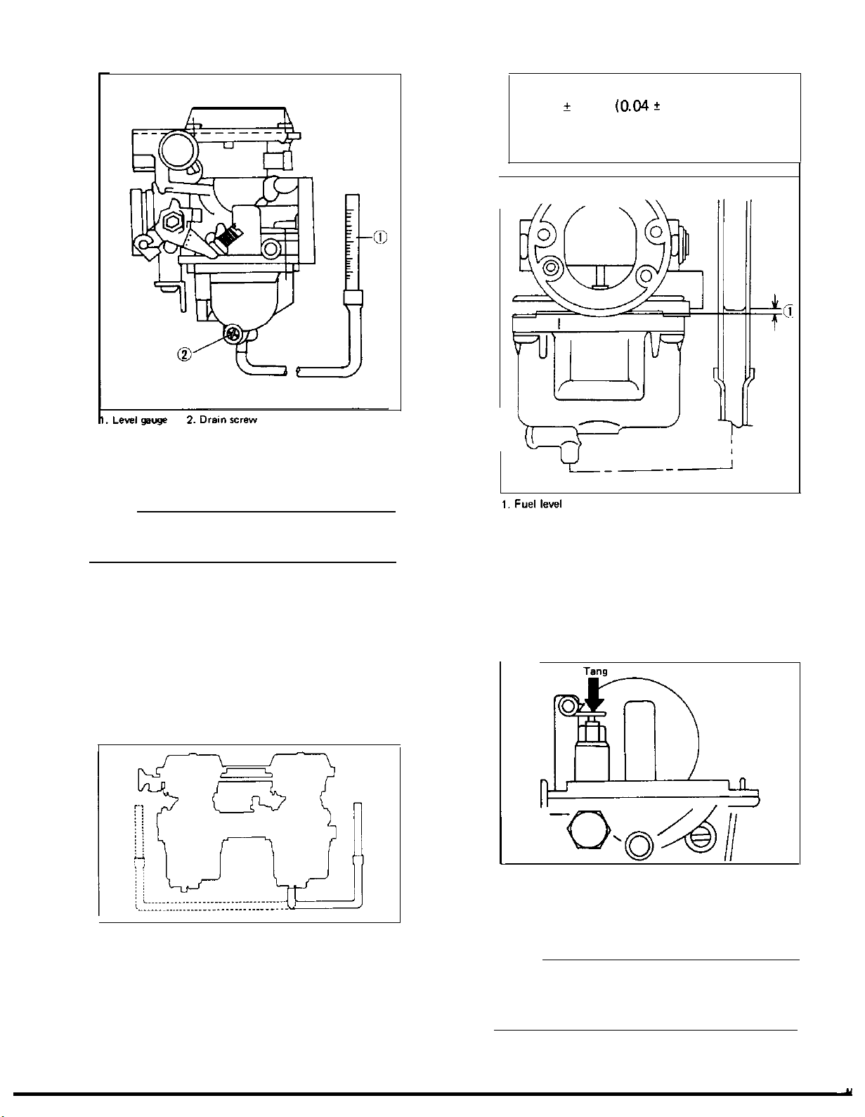
1.
Connect the level gauge (special tool) or
a vinyl pipe of 6 mm (0.24 in) in inside
diameter to the float bowl nozzle left or
right side carburetor.
2.
Set the gauge as shown and loosen the
drain screw.
-5
3. Start the engine and stop it after a few
minutes of run. This procedure is
sary
to obtain the correct fuel level.
neces-
Fuel level:
1 f 1 mm
from the carburetor mixing chamber
body edge.
(0.04?
0.04 in) above
YL___-A
NOTE:
Make sure the fuel petcock is “ON” or “RES”
oosition.
Note the fuel level and bring the gauge
4.
to the other end of the carburetor line
and repeat step 3 above. Note the fuel
level again and compare it with the
previous gauge reading. They should be
equal. If not, place a suitable size of
wooden piece or the. alike under the
center stand and adjust.
5. Check the fuel level one by one. The
level should be in the specified range.
6. If the fuel level is incorrect, remove the
carburetor assembly from the motorcycle and check the fuel
float assembly(s) for damage.
7. If no damage is found, correct the fuel
level by slightly bending the float arm
tang. Recheck the fuel level.
D. ENGINE OIL LEVEL MEASUREMENT
1.
Place the motorcycle on the center stand.
Warm up the engine for several minutes.
NOTE:
Be sure the motorcycle is positioned straight
up when checking the oil level; a slight tilt
toward the side can produce false readings.
valve(s)
and
-6-
Y
2
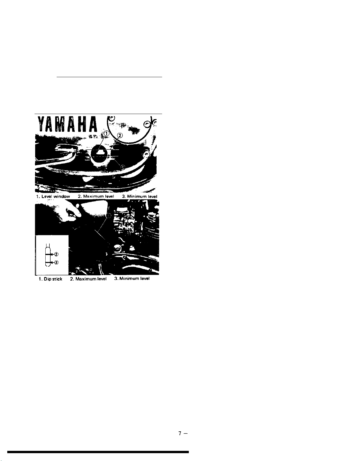
With the engine stopped, check the oil
level through the level window located at
the lower part of the right side crankcase
cover, or screw the dip stick completely
out and then the stick in the hole.
NOTE:
Wait a few minutes until the oil level settles
before checking. When checking engine oil
level with the dip stick, let the unscrewed dip
stick rest on the case threads.
1.
Dip stick
2.
Maximum
level
Minimum
level
3.
3. The oil level should be between maximum and minimum levels. If the level
is lower, add sufficient oil to raise it to
the proper level.
l-
 Loading...