


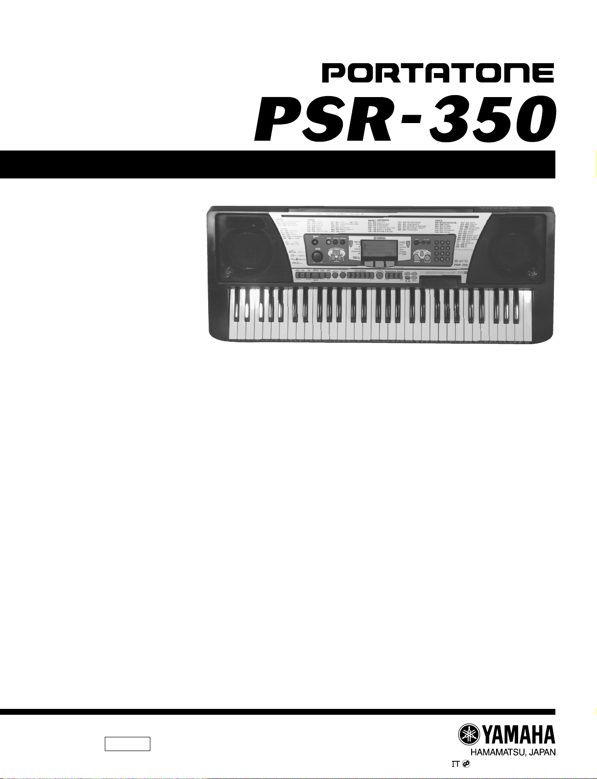
PSR-350
SERVICE MANUAL
■ CONTENTS
SPECIFICATIONS.............................................................................. 3
PANEL LAYOUT ................................................................................. 4
CIRCUIT BOARD LAYOUT & WIRING .............................................. 6
BLOCK DIAGRAM ............................................................................. 8
DISASSEMBLY PROCEDURE .......................................................... 9
LSI PIN DESCRIPTION ................................................................... 13
IC BLOCK DIAGRAM....................................................................... 16
CIRCUIT BOARDS .......................................................................... 16
TEST PROGRAM ............................................................................ 25
DATA BACKUP & INITIALIZATION .................................................. 28
MIDI IMPLEMENTATION CHART .................................................... 29
OVERALL CIRCUIT DIAGRAM
PARTS LIST
This document is printed on chlorine free (ECF) paper with soy ink.
1.412K-976 Printed in Japan ’01.05
PK 001653
PSR-350
2
IMPORTANT NOTICE
This manual has been provided for the use of authorized Yamaha Retailers and their service personnel. It has been assumed
that basic service procedures inherent to the industry, and more specifically Yamaha Products, are already known and
understood by the users, and have therefore not been restated.
WARNING : Failure to follow appropriate service and safety procedures when servicing this product may result in
personal injury, destruction of expensive components and failure of the product to perform as
specified. For these reasons, we advise all Yamaha product owners that all service required should
be performed by an authorized Yamaha Retailer or the appointed service representative.
IMPORTANT : This presentation or sale of this manual to any individual or firm does not constitute authoriza-tion,
certification, recognition of any applicable technical capabilities, or establish a principal-agent
relationship of any form.
The data provided is believ ed to be accurate and applicab le to the unit (s) indicated on the cov er. The research engineering,
and service departments of Yamaha are continually striving to improve Y amaha products. Modifications are , therefor , ine vitable
and changes in specification are subject to change without notice or obligation to retrofit. Should an y discrepancy appear to
exist, please contact the distributor’s Service Division.
WARNING : Static discharges can destroy expensive components. Discharge any static electricity your body
may have accumulated by grounding yourself to the ground bus in the unit (heavy gauge black wires
connect to this bus).
IMPORTANT : Turn the unit OFF during disassembly and par ts replacement. Recheck all work before you apply
power to the unit.
WARNING : CHEMICAL CONTENT NOTICE !
The solder used in the production of this product contains LEAD. In addition, other electrical/electronic and/or plastic
(where applicable) components may also contain traces of chemicals found by the California Health and Welfare Agency
(and possibly other entities) to cause cancer and/or birth defects or other reproductive harm.
DO NOT PLACE SOLDER, ELECTRICAL/ELECTRONIC OR PLASTIC COMPONENTS IN YOUR MOUTH FOR ANY
REASON WHAT SO EVER!
Avoid prolonged, unprotected contact betw een solder and your skin! When soldering, do not inhale solder fumes or expose
eyes to solder/flux vapor!
If you come in contact with solder or components located inside the enclosure of this product, wash your hands before
handling food.
■ WARNING
Components having special characteristics are marked Z and must be replaced with parts having specification equal to
those originally installed.

PSR-350
3
■ SPECIFICATIONS
Keyboards
• 61 standard-size keys (C1 - C6), with Touch Response and
Dynamic Filter.
Display
• Large multi-function LCD display (backlit)
Setup
• STANDBY/ON
• MASTER VOLUME : MIN - MAX
Panel Controls
• OVERALL (L, R), SONG, VOICE, STYLE, PORTABLE
GRAND, DJ, METRONOME, [0]-[9], [+](YES), [-](NO),
DEMO, TOUCH, HARMONY, Dict., L, R, TEMPO/TAP
Voice
• 116 panel voices + 12 drum kits + XG expanded voices +10
DJ voices
• Polyphony : 32
Auto Accompaniment
• 106 styles + Disk
• Accompaniment Control : ACMP ON/OFF, SYNC STOP,
SYNC START, START/STOP,
INTRO/ENDING,
MAINA/B(AUTO FILL)
• Fingering : Multi fingering
• Accompaniment Volume
Music Database
• 208
Yamaha Educational Suite
• Dictionary
• Lesson 1-4
One T ouch Setting
• Voice (for each style or song)
Overall controls
• Lesson R, L
• Octave
• Transpose
• Tuning
• Accompaniment/Song Volume
• Metronome Volume
• Reverb
• DSP
• Harmony
• Grade/Talking
• MIDI
Effects
• Reverb : 8 types
• DSP : 38 types
• Harmony : 26 types
Song
• 100 Songs + 5 User Songs
• Song Clear, Track Clear
Recording
• Song
User Song : 5 Songs
Recording Tracks : 1, 2, 3, 4, 5, CHORD
Disk
• Song Playback
•Save
• Load
• Delete
• Format
MIDI
• Initial Send
• Local on/off
Auxiliary jacks
• PHONES/OUTPUT, DC IN 12V, MIDI IN/OUT, SUSTAIN
Amplifier
• 3.0W + 3.0W
Speakers
• 12cm x 2 + 3cm x 2
Power Consumption
• 22 W (when using PA-5C power adaptor)
Power Supply
• Adaptor : Yamaha PA-5C AC power adaptor
• Batteries : Six “D” size, R20P (LR20) or equivalent batteries
Dimensions (W x D x H)
• 952 x 387 x 169 mm (37-1/2" x 15-1/4" x 6-2/3")
Weight
• 8.5 kg (18 lbs., 12 oz.)
Supplied Accessories
• Music Stand
• Data Disk
• Owner’s Manual
• Song Book
Optional Accessories
• Headphones : HPE-150
• AC power adaptor : PA-5C
• Footswitch : FC4, FC5
• Keyboard stand : L-6

PSR-350
4
● Top Panel
■ PANEL LAYOUT
q
w
e
i
o
!8!7 !9 @0 @1 @2
@3
r t
A
A’
GrandPno
000
001
@4 @5
!0 !2!1
@6
@7
y y
!3 !5
!4
u
!6
A
A’
PSR-350
5
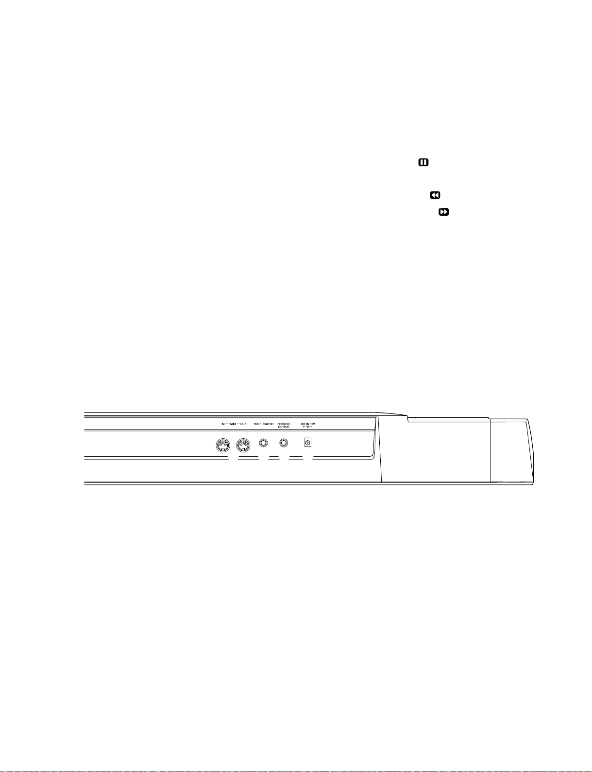
● Rear Panel
q Power switch ([STANDBY/ON])
w [MASTER VOLUME] dial
e [DEMO] button
r [TOUCH] button
t [HARMONY] button
y Overall (left, right) buttons
u [DUAL] and [SETTING H/G] buttons
i [Dict.] (DICTIONARY) button
o LESSON [L] (Left) and [R] (Right) buttons
!0 [SONG] button
!1 [STYLE] button
!2 [VOICE] button
!3 [PORTABLE GRAND] button
@9@8 #0 #1
!4 [METRONOME] button
!5 [DJ] button
!6 Numeric keypad, [+/YES] and [-/NO] but-tons
!7 [ACMP ON/OFF] / [A-B REPEAT] button
!8 [SYNC STOP] button
!9 [SYNC START] / [ PAUSE] button
@0 [START/STOP] button
@1 [INTRO/ENDING] / [
REW] button
@2 [MAIN/AUTO FILL] / [
FF] button
@3 [TEMPO/TAP] button
@4 [SONG MEMORY] buttons
@5 [MUSIC DATABASE] button
@6 [REGISTRATION MEMORY] buttons
@7 Disk Drive
@8 [MIDI IN], [MIDI OUT] connectors
@9 [FOOT SWITCH] jack
#0 [PHONES/OUTPUT] jack
#1 [DC IN 12V] jack

PSR-350
6
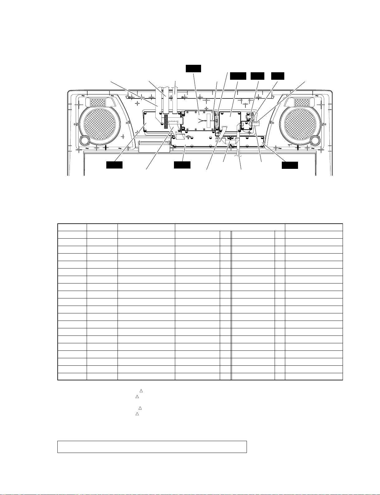
■ CIRCUIT BOARD LAYOUT & WIRING
● Lower case side
● Upper case side
[WH200]
[C40]
[C50]
[440]
Speaker (Woofer-R)
Speaker (Woofer-L)
MKS5
MK-L
DM
AM
MK-H
[AM-WH999] [AM-WH998]
Speaker (Tweeter-R) Speaker (Tweeter-L)
FDD
AM
[450]
Speaker (Tweeter-R) Speaker (Tweeter-L)
[PN-WH11]
[L70]
[PN-WH9]
TW
-R
TW
-L
[PN-WH2]
[460]
[PN-WH1]
[AM-WH3]
[AM-WH2]
[PN-WH10]
TW
-R
TW
-L
[450] [460] [AM-WH2] [AM-WH3] [AM-WH7] [PN-WH10]
[PN-WH11][L70]
PSR-350
7
● Upper case side
[WH200] [L70]
PN3
LCD
PN4 PW VR
PN1
440 - - KB DM-CN102 *6 *1 MKS5-CN1 *6 *1 6P (V718860)
450 V3819800 FDD DM-CN301 *1 FDD-CN1 *3 34P
460 - - FDPS AM-CN908 *1 FDD-CN2 *2 2/4P (V718900)
C40 - - SP Speaker (Wo) AM-CN802 *4 4P (V718870)
C50 - - BAT Battery AM-CN903 *5 2P (V705790)
AM-WH2 - - PS AM-CN901 DM-CN101 *1 7P (V718820)
AM-WH3 - - DJ AM-CN602 DM-CN601 *1 6P (V718830)
AM-WH7 - - EP1 AM-EP1 AM-EP2 L=120 (V719460)
AM-WH998
- - TW AM-CN909 TW-L (V718880)
AM-WH999
- - TW AM-CN910 TW-R (V718880)
WH200 - - LCD LCD-CN1 DM-CN175 *1 12P (V718800)
PN-WH1 - - PN1 PN 1-CN1 DM-CN701 *1 8P (V718750)
PN-WH2 - - PN2 PN 1-CN2 DM-CN702 *1 10P (V718760)
PN-WH4 - - PN3 PN 2-CN4 PN 1-CN3 *1 15P (V718770)
PN-WH5 - - PN4 PN 2-CN5 PN 4-CN8 *1 7P (V718780)
PN-WH6 - - PN5 PN 2-CN6 PN 3-CN7 6P (V718790)
PN-WH9 - - VR1 VR-CN9 DM-CN501 *1 5P (V718840)
PN-WH10 - - VR2 VR-CN10 AM-CN801 *1 5P (V718850)
PN-WH11 - - SW PW-CN11 AM-CN902 *1 4P (V719860)
L70 - - BLT Back Light AM-CN907 *1 2P (V718810)
* The parts with “–” in “Part No.” are not available as spare parts.
* 1 : Edge mark is adjusted to Pin 1 mark ( mark).
* 2 : Red wire is adjusted to Pin 1 mark (
mark).
* 3 : Connector hook is located at the upper side of FDD.
* 4 : White wire is adjusted to Pin 1 mark (
mark).
* 5 : Red wire is adjusted to Pin 1 mark (
mark).
* 6 : Be sure to make a correct match when connecting MKS5(CN1) and DM(CN102).
Connecting the connectors in the wrong way around may cause damage to the MKS5 circuit board.
Location Part No. Connector Assembly Destination Remarks
[PN-WH2] [PN-WH1]
PN2
Back Light Assembly
[PN-WH11]
[PN-WH10]
[PN-WH9]
[PN-WH6]
[PN-WH5]
[PN-WH4]
Caution: Be sure to attach the removed filament tape just as it was before removal.
PSR-350
8
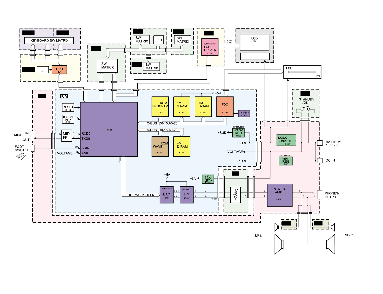
■ BLOCK DIAGRAM
5MHz
CN3
CN2
CN4
CN1
BACK LIGHT
CN301
CN102
CN702
CN701
CN1
CN2
CN3
CN4
CN5
CN6
CN7
CN01
CN101
CN902
CN903
32M
32M
SWX00B
CN602
CN601
IC601
CN715
1
CN9 CN10
VR1
MASTER
VOLUME
CN801
CN909
CN802
CN910
LA4705NA
14
15
NJM78L05A
CN901
CN907 CN908
CN11
CN8
TWEETER
WOOFER
TWEETER
WOOFER
28CA1-889533
MKS5
MK-L MK-H
PN1
PN2
PN4
PN3
LCD
AM
VR
PW
TW -R
TW -L

PSR-350
9
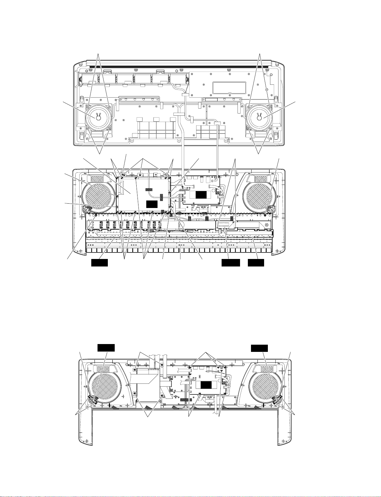
■ DISASSEMBLY PROCEDURE
3. DM Circuit Board, Shield Box U and L
(Time required : About 10 min.)
3-1. Remove the lower case assembly.
(See procedure 1)
3-2. Remove the two (2) screws marked [270B] and
the thirteen (13) screws marked [290]. The shield
box U and the DM circuit board can then be
removed. (Fig. 4)
3-3. Remove the three (3) screws marked [260A]. The
shield box L can then be removed. (Fig. 4)
4. Floppy Disk Drive Assembly
(Time required : About 10 min.)
4-1. Remove the lower case assembly.
(See procedure 1)
4-2. Remove the DM circuit board and the shield box
U and L. (See procedure 3)
4-3. Remove the four (4) screws marked [300]. The
floppy disk assembly can then be removed. (Fig. 5)
5. AM Circuit Board
(Time required : About 10 min.)
5-1. Remove the lower case assembly.
(See procedure 1)
5-2. Remove the seven (7) scre ws mar ked [260B]. The
AM circuit board can then be removed. (Fig. 5)
[270A] :Bind Head Tapping Screw-P 3.0X12 MFZN2Y (EP600300)
[280A] :Bind Head Tapping Screw-P 3.0X25 MFZN2Y (VK228100)
(Fig. 1)
2. Spring T erminal
(Time required : About 10 min.)
2-1. Remove the lower case assembly.
(See procedure 1)
2-2. Remove the BAT connector assembly (red/black)
soldered to the spring terminal (+)/(-). (Fig. 2)
2-3. Remove the battery cover assembly. (Fig. 1)
2-4. Remove the spring terminal by releasing hooks (2
locations for each). (Fig. 3)
(Fig. 2)
(Fig. 3)
1. Lower Case Assembly
(Time required : About 5 min.)
1-1. Remove the fourteen (14) screws marked [270A] and the four (4) scr ews marked [280A].
The lower case assembly can then be removed. (Fig. 1)
[270A] [270A] [270A]
[270A]
[270A]
[280A] [280A]
[270A]
Lower Case AssemblyBattery Cover Assembly
Spring Terminal
Hook
Hook
Lower Case
Assembly
BAT Connector
Assembly (Black)
BAT Connector
Assembly (Red)
PSR-350
10
[30] : Bind Head Tapping Screw-P 3.0X8 MFZN2Y (EP600280)
[260A] :Bind Head Tapping Screw-P 3.0X8 MFZN2Y (EP600280)
[270B] :Bind Head Tapping Screw-P 3.0X12 MFZN2Y (EP600300)
[280B] :Bind Head Tapping Screw-P 3.0X25 MFZN2Y (VK228100)
[290] : Bind Head Tapping Screw-B 3.0X8 MFZN2Y (EP600250)
[C30] : Bind Head Tapping Screw-P 4.0X8 MFZN2BL (VB931600)
(Fig. 4)
[260] : Bind Head Tapping Screw-P 3.0X8 MFZN2Y (EP600280)
[300] : Sems Pan Head Screw 3.0X10 MFZN2Y (V5115200)
(Fig. 5)
[260A]
[C30]
[30]
Speaker (Woofer) Speaker (Woofer)
[C30]
[280B]
[270B]
[290]
[270B]
[280B]
Keyboard
Assembly
Shield Box U
[C30][C30]
[290] [290] [290]
[290]
[290] [290]
Speaker (Tweeter)
Speaker (Tweeter)
[260B][300]
[260J]
[260J]
[260B]
[300]
[260B]
MK-LMK-H MKS5
DM
AM
AM
FDD
TW
-LTW
-R
Shield Box L
 Loading...