


Trane 4TVW0007B100NB, 4TVW0009B100NB, 4TVW0012B100NB, 4TVW0018B100NB, 4TVW0020B100NB Installation and Maintenance Manual
...Installation, Operation,
and Maintenance
Variable Refrigerant Flow System
High-Wall Indoor Unit Series
Models: 4TVW0007B100NB, 4TVW0009B100NB, 4TVW0012B100NB,
4TVW0018B100NB, 4TVW0020B100NB, 4TVW0024B100NB
 SAFETY WARNING
Only qualified personnel should install and service the equipment. The installation, starting up, and servicing of heating, ventilating, and air-conditioning equipment can be hazardous and requires specific knowledge and training. Improperly installed, adjusted or altered equipment by an unqualified person could result in death or serious injury. When working on the equipment, observe all precautions in the literature and on the tags, stickers, and labels that are attached to the equipment.
February 2013 |
VRF-SVX30A-EN |

Introduction
Read this manual thoroughly before operating or servicing this unit.
Warnings, Cautions, and Notices
Safety advisories appear throughout this manual as required. Your personal safety and the proper operation of this machine depend upon the strict observance of these precautions.
The three types of advisories are defined as follows:
 WARNING
 CAUTIONs
NOTICE
Indicates a potentially hazardous situation which, if not avoided, could result in death or serious injury.
Indicates a potentially hazardous situation which, if not avoided, could result in minor or moderate injury. It could also be used to alert against unsafe practices.
Indicates a situation that could result in equipment or property-damage only.
Important Environmental Concerns
Scientific research has shown that certain man-made chemicals can affect the earth’s naturally occurring stratospheric ozone layer when released to the atmosphere. In particular, several of the identified chemicals that may affect the ozone layer are refrigerants that contain Chlorine, Fluorine and Carbon (CFCs) and those containing Hydrogen, Chlorine, Fluorine and Carbon (HCFCs). Not all refrigerants containing these compounds have the same potential impact to the environment. Trane advocates the responsible handling of all refrigerantsincluding industry replacements for CFCs such as HCFCs and HFCs.
Important Responsible Refrigerant Practices
Trane believes that responsible refrigerant practices are important to the environment, our customers, and the air conditioning industry. All technicians who handle refrigerants must be certified. The Federal Clean Air Act (Section 608) sets forth the requirements for handling, reclaiming, recovering and recycling of certain refrigerants and the equipment that is used in these service procedures. In addition, some states or municipalities may have additional requirements that must also be adhered to for responsible management of refrigerants. Know the applicable laws and follow them.
 WARNING
Proper Field Wiring and Grounding
Required!
Failure to follow code could result in death or serious injury. All field wiring MUST be performed by qualified personnel. Improperly installed and grounded field wiring poses FIRE and ELECTROCUTION hazards. To avoid these hazards, you MUST follow requirements for field wiring installation and grounding as described in NEC and your local/state electrical codes.
 WARNING
Personal Protective Equipment (PPE)
Required!
Failure to wear proper PPE for the job being undertaken could result in death or serious injury. Technicians, in order to protect themselves from potential electrical, mechanical, and chemical hazards, MUST follow precautions in this manual and on the tags, stickers, and labels, as well as the instructions below:
•Before installing/servicing this unit, technicians MUST put on all PPE recommended for the work being undertaken. ALWAYS refer to appropriate MSDS sheets and OSHA guidelines for proper PPE.
•When working with or around hazardous chemicals, ALWAYS refer to the appropriate MSDS sheets and OSHA guidelines for information on allowable personal exposure levels, proper respiratory protection, and handling recommendations.
•If there is a risk of arc or flash, technicians MUST put on all PPE in accordance with NFPA 70E or other country-specific requirements for arc flash protection, PRIOR to servicing the unit.
Copyright
This document and the information in it are the property of Trane and may not be used or reproduced in whole or in part, without the written permission of Trane. Trane reserves the right to revise this publication at any time and to make changes to its content without obligation to notify any person of such revision or change.
Trademarks
All trademarks referenced in this document are the trademarks of their respective owners.
© 2013 Trane All rights reserved |
VRF-SVX30A-EN |
Table of Contents
Introduction . . . . . . . . . . . . . . . . . . . . . . . . . . . . . . . . . . . . . . . . . . . . . . . . . . . . . . . . . . . . 2
Warnings, Cautions, and Notices . . . . . . . . . . . . . . . . . . . . . . . . . . . . . . . . . . . . . 2
Model Number Description . . . . . . . . . . . . . . . . . . . . . . . . . . . . . . . . . . . . . . . . . . . . . . 5
Preparing for Installation . . . . . . . . . . . . . . . . . . . . . . . . . . . . . . . . . . . . . . . . . . . . . . . . 6
Accessories . . . . . . . . . . . . . . . . . . . . . . . . . . . . . . . . . . . . . . . . . . . . . . . . . . . . . . . 6
Location Considerations . . . . . . . . . . . . . . . . . . . . . . . . . . . . . . . . . . . . . . . . . . . . 6
Service Clearances . . . . . . . . . . . . . . . . . . . . . . . . . . . . . . . . . . . . . . . . . . . . . . . . 7
Installation . . . . . . . . . . . . . . . . . . . . . . . . . . . . . . . . . . . . . . . . . . . . . . . . . . . . . . . . . . . . . 8
Mounting the Unit . . . . . . . . . . . . . . . . . . . . . . . . . . . . . . . . . . . . . . . . . . . . . . . . . 8
Purging the Unit . . . . . . . . . . . . . . . . . . . . . . . . . . . . . . . . . . . . . . . . . . . . . . . . . . . 9
Installing Refrigerant Piping . . . . . . . . . . . . . . . . . . . . . . . . . . . . . . . . . . . . . . . . 10
Leak Testing Pipe Connections . . . . . . . . . . . . . . . . . . . . . . . . . . . . . . . . . . . . . 12
Installing the Drain System . . . . . . . . . . . . . . . . . . . . . . . . . . . . . . . . . . . . . . . . . 13
Insulation . . . . . . . . . . . . . . . . . . . . . . . . . . . . . . . . . . . . . . . . . . . . . . . . . . . . . . . . . . . . . 15
Refrigerant Pipes . . . . . . . . . . . . . . . . . . . . . . . . . . . . . . . . . . . . . . . . . . . . . . . . . 15
Drainage Hose . . . . . . . . . . . . . . . . . . . . . . . . . . . . . . . . . . . . . . . . . . . . . . . 15
Wiring the Unit . . . . . . . . . . . . . . . . . . . . . . . . . . . . . . . . . . . . . . . . . . . . . . . . . . . . . . . . 16
Power . . . . . . . . . . . . . . . . . . . . . . . . . . . . . . . . . . . . . . . . . . . . . . . . . . . . . . 16
Communication . . . . . . . . . . . . . . . . . . . . . . . . . . . . . . . . . . . . . . . . . . . . . . 16
Electronic Expansion Valve (EEV) Kit . . . . . . . . . . . . . . . . . . . . . . . . . . . . . 16
Configuration . . . . . . . . . . . . . . . . . . . . . . . . . . . . . . . . . . . . . . . . . . . . . . . . . . . . . . . . . 18
Using the VRF Wireless Remote Control . . . . . . . . . . . . . . . . . . . . . . . . . . . . . 18 The 2-Digit Segments . . . . . . . . . . . . . . . . . . . . . . . . . . . . . . . . . . . . . . . . . 20 Configuration Modes . . . . . . . . . . . . . . . . . . . . . . . . . . . . . . . . . . . . . . . . . 20 Mode 2: Option Setting . . . . . . . . . . . . . . . . . . . . . . . . . . . . . . . . . . . . . . . . 21 Mode 5: Option Setting . . . . . . . . . . . . . . . . . . . . . . . . . . . . . . . . . . . . . . . . 23 Mode A: Addressing . . . . . . . . . . . . . . . . . . . . . . . . . . . . . . . . . . . . . . . . . . 25 Mode d: Specific Digit Changing . . . . . . . . . . . . . . . . . . . . . . . . . . . . . . . . 26
Operation . . . . . . . . . . . . . . . . . . . . . . . . . . . . . . . . . . . . . . . . . . . . . . . . . . . . . . . . . . . . . 29
Components . . . . . . . . . . . . . . . . . . . . . . . . . . . . . . . . . . . . . . . . . . . . . . . . . . . . . 29
Operating Tips . . . . . . . . . . . . . . . . . . . . . . . . . . . . . . . . . . . . . . . . . . . . . . . . . . . . 29
Internal Protections . . . . . . . . . . . . . . . . . . . . . . . . . . . . . . . . . . . . . . . . . . . . . . . 30
Operating Ranges . . . . . . . . . . . . . . . . . . . . . . . . . . . . . . . . . . . . . . . . . . . . . . . . . 30
Operating Mode for Heat Pump Systems . . . . . . . . . . . . . . . . . . . . . . . . . . . . . 30
Cleaning the Exterior . . . . . . . . . . . . . . . . . . . . . . . . . . . . . . . . . . . . . . . . . . . . . . 30
Cleaning the Air Filter . . . . . . . . . . . . . . . . . . . . . . . . . . . . . . . . . . . . . . . . . . . . . 30
Periodic Maintenance Checks . . . . . . . . . . . . . . . . . . . . . . . . . . . . . . . . . . . . . . . 31
VRF-SVX30A-EN |
3 |

Troubleshooting . . . . . . . . . . . . . . . . . . . . . . . . . . . . . . . . . . . . . . . . . . . . . . . . . . . . . . . 32
. . . 35
Basic Warranty . . . . . . . . . . . . . . . . . . . . . . . . . . . . . . . . . . . . . . . . . . . . . . . . . . . 35
Exclusions and Limitations . . . . . . . . . . . . . . . . . . . . . . . . . . . . . . . . . . . . . . . . . 35
4 |
VRF-SVX30A-EN |

Model Number Description
4 |
T |
V |
D |
0 |
0 |
1 |
8 |
A |
1 |
0 |
0 |
N |
A |
|
|
|
|
|
|
|
|
|
|
|
|
|
|
1 |
2 |
3 |
4 |
5 |
6 |
7 |
8 |
9 |
10 |
11 |
12 |
13 |
14 |
|
|
|
|
|
|
|
|
|
|
|
|
|
|
Digit 1: Refrigerant
4 = R410A
Digit 2: Brand name
T = Trane
Digit 3: System type
V = Variable Refrigerant Flow
Digit 4: Configuration Type (also see separate tab)
B= mini 4-way cassette
C= 4-way cassette
D= MSP duct type (mid-pressure)
E= 1-way cassette
L = Slim duct type (low pressure) A = HSP duct type high pressure) X = Ceiling
W = High-wall
Digit 5: Reserved for future use
0 = Not currently used
Digit 6, 7, 8: Nominal capacity (Btu/h x 1,000)
006 = 6,000 Btu/h |
020 = 20,000 Btu/h |
060 = 60,000 Btu/h |
|
007 |
= 7,000 Btu/h |
024 = 24,000 Btu/h |
068 = 68,000 Btu/h |
009 = 9,000 Btu/h |
030 = 30,000 Btu/h |
076 = 76,000 Btu/h |
|
012 |
= 12,000 Btu/h |
036 = 36,000 Btu/h |
096 = 96,000 Btu/h |
018 |
= 18,000 Btu/h |
048 = 48,000 Btu/h |
|
Digit 9: Major development sequence
B = Second development sequence
Digit 10: Electric power supply characteristics
1 = 220/60/1
B = 220–240/50/1
Digit 11: Reserved for future use
0 = Not currently used
Digit 12: Controller
0 = None
R = Remote control standard
W = Wired control standard
Digit 13: Region of sale
N = North America (UL or ETL)
Digit 14: Minor design sequence
A = First design sequence
B = Second design sequence
VRF-SVX30A-EN |
5 |
Preparing for Installation
Preparing for Installation
Accessories
In addition to product literature, the following accessories are supplied with this unit. The type and quantity may differ, depending on the model.
Installation plate
Location Considerations
When deciding on a location for the indoor unit, the following factors must be considered:
•The air inlet and outlet must be unobstructed.
•The wall or ceiling must support the weight of the unit.
•The wall or ceiling must not be subject to vibration.
•Pre-plan for easy and short routing of the refrigerant tubing and wiring to the outdoor unit.
•The air must circulate freely in the area to be cooled/heated.
•Sufficient clearance must be maintained around the unit.
•Condensate must be managed correctly and safety away from the unit.
•The unit should be installed in a way that prevents unauthorized access.
•The unit must not be installed in an area that is damp or could come into contact with water (such as a laundry room).
•The unit must not be exposed to direct sunshine or to other direct heat sources.
•The filter must be able to be removed and cleaned easily.
•The unit should be placed as far as possible from fluorescent lights so the remote control is not subject to interference.
•Care should be taken to prevent harmonics generated by loose or unsupported material in close proximity to a running unit.
•The unit must not be installed in an area that is exposed to salt, machine oil, sulfide gas, or corrosive environmental conditions.
6 |
VRF-SVX30A-EN |
Preparing for Installation
Service Clearances
|
11.81 in. (300 mm) |
4.9 in. (125 mm) |
4.9 in. (125 mm) |
|
|
|
|
|
|
|
|
|
|
VRF-SVX30A-EN |
7 |
|||

Installation
Installation
Review “Installation Considerations” before proceeding with installation.
Follow the procedures in these sections in the order given.
Notes:
•Install the Y-joint before installing the indoor unit.
•Install an electronic expansion valve (EEV) on this unit. Refer to the EEV Kit installation guide (VRF-SVN43) for information.
Mounting the Unit
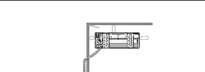
The wiring, piping, and drain hose can be connected to run from the indoor unit in one of the following directions:
•Right (A)
•Left (B)
•Underside (C)
•Rear (right or left)
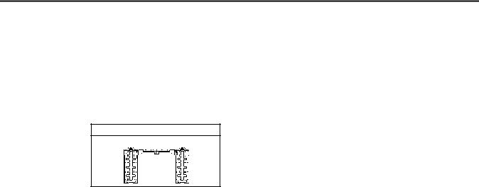
1.Determine the position of the piping and drain hose and drill a 2.56 in. (65 mm) hole that slants slightly upward.
2.Attach the installation plate to a wall or a window frame, considering the weight of the unit. Refer to the following dimensional diagrams.
•If you are mounting the installation plate to a concrete wall, use anchor bolts making sure they do not project more than 0.8 in. (20 mm).
•For an existing structure, attach the installation plate to wall studs or take other necessary precautions for supporting the unit.
•For mounting on a window frame, install wood mounting supports for the unit. Attach the installation plate to the wooden uprights using tapping screws.
Pipe hole: |
|
|
|
|
|
|
|
|
|
|
Pipe hole: |
|
|
|
|
|
|
|
|
|
|
|||||||||||
Pipe hole: |
|
|
|
|
|
|
|
|
|
|
|
|
|
|
|
|
|
|
|
|
||||||||||||
2.56 (65) |
|
|
|
|
|
|
|
|
|
|
|
|
|
|
2.56 (65) |
|
|
|
|
|
|
|
|
|
|
|
|
|
||||
(27) |
|
|
|
|
|
|
|
|
|
|
|
(27) |
|
|
(34) |
|
|
|
|
|
|
|
|
|
|
|
|
(34) |
||||
|
|
|
|
|
|
|
|
|
|
|
|
|
|
|
|
|
|
|
|
|
|
|||||||||||
|
|
|
|
|
|
|
|
|
|
|
|
|
|
|
|
|
|
|
|
|
||||||||||||
|
|
|
|
|
|
|
|
|
|
|
1.06 |
|
|
|
|
|
|
|
|
|
|
|
|
|
|
|
1.34 |
|||||
1.06 |
|
|
|
|
|
|
|
|
|
|
|
|
|
1.34 |
|
|
|
|
|
|
|
|
|
|
|
|
|
|
||||
|
|
|
|
|
|
|
|
|
|
|
|
|
|
|
|
|
|
|
|
|
|
|
|
|
|
|
||||||
|
|
|
|
|
|
|
|
|
|
|
|
4TVW0018B100NB |
|
|
|
|
|
|
||||||||||||||
|
|
|
|
|
4.72 |
|
|
4TVW0007B100NB |
|
|
2.68 |
|
|
|
|
|
|
|
|
|
5.51 |
|
|
|
2.68 |
|
|
|
|
|
||
|
|
|
|
|
|
|
4TVW0009B100NB |
|
|
|
|
|
|
|
|
|
|
|
|
4TVW0020B100NB |
|
|
|
|
|
|
||||||
|
|
|
|
|
|
|
(140) |
|
|
|
|
|
|
|||||||||||||||||||
|
|
|
|
(120) |
|
|
|
|
|
|
|
|
|
|
|
|
|
|
|
|
|
|
|
|||||||||
|
|
|
|
|
|
|
|
|
|
|
|
|
|
(68) |
|
|
|
|
|
|||||||||||||
|
|
|
|
|
|
4TVW0012B100NB |
(68) |
|
|
|
|
|
|
|
|
|
|
4TVW0024B100NB |
|
|
|
|
|
|||||||||
|
|
|
|
|
|
|
|
|
|
|
|
|
|
|
|
|
|
|
|
|
|
|
|
|
|
|
|
|
|
|
|
|
3. Install the unit on the plate.
8 |
VRF-SVX30A-EN |
Installation
Purging the Unit
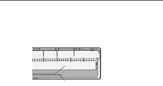
The unit is shipped from the factory with a holding charge of nitrogen. All of this gas must be purged from the unit.
To purge the unit, remove the caps from the ends of both gas and liquid refrigerant pipes. Make sure all gas has escaped before connecting the piping.
Note: To prevent dirt or foreign objects from getting into the pipes during installation, do not remove the caps completely until you are ready to connect the piping.
 Gas refrigerant port
 Liquid refrigerant port
VRF-SVX30A-EN |
9 |

Installation
Installing Refrigerant Piping
Connect field-supplied piping using flared connections (not supplied) or by brazing. The large unit port is for gas refrigerant; the small one is for liquid refrigerant.
Cut or extend field-supplied piping as needed. Use the following procedures.
NOTICE
System Failure!
If brazing is used for pipe connections, a nitrogen purge is required to prevent the formation of copper oxides inside the piping. Failure to follow this procedure could damage the system.
•Before connecting the pipes, make sure they are free of dirt and debris.
•Use insulated, unwelded, degreased, and deoxidized copper pipe (Cu-DHP type according to ISO 1337 or UNI EN 12735-1) suitable for an operating pressure of at least 609.15 psi (4200 kPa) and a burst pressure of at least 3002.28 psi (20,700 kPa). Copper pipe for hydro-sanitary applications is unsuitable.
•For sizing and limits (height difference, line length, maximum bends, refrigerant charge, and so on) see the outdoor unit installation manual.
•All refrigerant connections must be accessible for servicing and maintenance.
Pipe Cutting
Required tools:
•Pipe cutter
•Reamer
•Pipe holder
1.Using a pipe cutter, cut the pipe so that the cut edge is at 90° to the side of the pipe.
2.Use a reamer to remove all burrs at the cut edge.
See examples of correctly and incorrectly cut pipes.
Correct: 90º
Oblique |
Rough |
Burr |
Flared Pipe Connections
Clutch type and wing nut type flare tools are available for flared pipe connections.
1.Slide the flare nut over the pipe to be flared.
2.Slide the end of the pipe into the hole on the flaring bar that fits the pipe, leaving a length of pipe, determined by tool type (see table), extending above the flaring bar. Clamp it down.
Length of pipe extending above flare bar |
Flaring
bar
Pipe
10 |
VRF-SVX30A-EN |
Installation
R-410A clutch type |
Conventional flare tool |
||
Clutch type |
Wing nut type |
||
|
|||
0–0.020 in. |
0.04–0.06 in. |
0.06–0.08 in. |
|
|
|
|
|
|
|
|
|
3.Attach the yoke to the flaring bar, centering the conical part over the end of the pipe that is extending above the flaring bar.
4.Tighten the yoke securely to flare the end of the pipe.
Yoke
Flaring bar
Copper pipe
Flare nut
5.Remove the pipe. The end of the pipe that you flared should look like the end of a trumpet. See examples of correctly and incorrectly flared pipes.
Correct |
Inclined |
Damaged Cracked |
Uneven |
|
|
surface |
thickness |
6.Align the pipes and tighten the flare nuts manually and then with a spanner torque wrench, applying the torque according to pipe dimensions:
|
|
Flare |
Outer diameter |
Connection |
dimension |
(in. [mm]) |
torque (ft·lb) |
(in.) |
1/4 (6.35) |
10.3–13.3 ft·lb |
0.34–0.36 |
|
|
|
3/8 (9.52) |
25.1–31.0 ft·lb |
0.50–0.52 |
|
|
|
1/2 (12.70) |
36.1–45.0 ft·lb |
0.64–0.65 |
|
|
|
5/8 (15.88) |
50.2–60.5 ft·lb |
0.76–0.78 |
|
|
|
Flare shape (in.)
|
R.016–.031 |
90°±2° |
45°±2° |
VRF-SVX30A-EN |
11 |
Installation
Leak Testing Pipe Connections
 WARNING
Confined Space Hazards!
Do not work in confined spaces where refrigerant or other hazardous, toxic or flammable gas may be leaking. Refrigerant or other gases could displace available oxygen to breathe, causing possible asphyxiation or other serious health risks. Some gases may be flammable and or explosive. If a leak in such spaces is detected, evacuate the area immediately and contact the proper rescue or response authority. Failure to take appropriate precautions or to react properly to such potential hazards could result in death or serious injury.
 WARNING
Explosion Hazard!
Never use an open flame to detect gas leaks. It could result in an explosion. Use a leak test solution for leak testing. Failure to follow recommended safe leak test procedures could result in death or serious injury or equipment or property-only-damage.
Use only dry nitrogen with a pressure regulator for pressurizing unit. Do not use acetylene, oxygen or compressed air or mixtures containing them for pressure testing. Do not use mixtures of a hydrogen containing refrigerant and air above atmospheric pressure for pressure testing as they may become flammable and could result in an explosion. Refrigerant, when used as a trace gas should only be mixed with dry nitrogen for pressurizing units. Failure to follow these recommendations could result in death or serious injury or equipment or property-only damage.
Do not exceed unit nameplate design pressures when leak testing system. Failure to follow these instructions could result in an explosion causing death or serious injury.
Notes:
•All required piping pressure tests must be completed in accordance with national and/or local codes.
•When leak-testing refrigerant systems, observe all safety precautions.
•Leak test only one circuit at a time to minimize system exposure to potentially harmful moisture in the air.
•Use R-410A refrigerant gas as a tracer for leak detection and use oil-pumped dry nitrogen to develop required test pressures.
1.Close liquid line angle valve.
2.Connect R-410A refrigerant cylinder to high side charging port (at condenser or field supplied discharge line access port). Add refrigerant to reach pressure of 12 to 15 psig.
3.Disconnect refrigerant cylinder. Connect dry nitrogen cylinder to high side charging port and increase pressure to 150 psig. Do not exceed high side (discharge) unit nameplate design pressure. Do not subject low side (suction) components to high side pressure.
4.Check all piping joints, valves, etc. for leaks. Recommend using electronic detector capable of measuring 0.1 oz/year leak rate.
5.If a leak is located, use proper procedures to remove the refrigerant/nitrogen mixture, break connections and make repairs. Retest for leaks.
6.Make sure all service valves are open.
12 |
VRF-SVX30A-EN |
 Loading...