


 Loading...
Integration Manual
Trane Communicating Thermostats (BACnet)
Building Automation System |
 SAFETY WARNING
Only qualified personnel should install and service the equipment. The installation, starting up, and servicing of heating, ventilating, and air-conditioning equipment can be hazardous and requires specific knowledge and training. Improperly installed, adjusted or altered equipment by an unqualified person could result in death or serious injury. When working on the equipment, observe all precautions in the literature and on the tags, stickers, and labels that are attached to the equipment.
August 2011 |
BAS-SVP10A-EN |

Copyright
© 2011 Trane All rights reserved
This document and the information in it are the property of Trane and may not be used or reproduced in whole or in part, without the written permission of Trane. Trane reserves the right to revise this publication at any time and to make changes to its content without obligation to notify any person of such revision or change.
Trademarks
Trane and its logo are trademarks of Trane in the United States and other countries. All trademarks referenced in this document are the trademarks of their respective owners.
Warnings, Cautions, and Notices
Warnings, cautions, and notices are provided in appropriate places throughout this document:
 WARNING
 CAUTIONs
NOTICE:
Indicates a potentially hazardous situation which, if not avoided, could result in death or serious injury.
Indicates a potentially hazardous situation which, if not avoided, could result in minor or moderate injury. It could also be used to alert against unsafe practices.
Indicates a situation that could result in equipment or property-damage only accidents.

Table of Contents |
|
Overview . . . . . . . . . . . . . . . . . . . . . . . . . . . . . . . . . . . . . . . . . . . . . . . . . . . . . . . . . . . . . . |
5 |
Product Description . . . . . . . . . . . . . . . . . . . . . . . . . . . . . . . . . . . . . . . . . . . . . . . . |
5 |
Related Documents . . . . . . . . . . . . . . . . . . . . . . . . . . . . . . . . . . . . . . . . . . . . . . . . |
6 |
Planning Your Integration . . . . . . . . . . . . . . . . . . . . . . . . . . . . . . . . . . . . . . . . . . . |
6 |
“How To” Information . . . . . . . . . . . . . . . . . . . . . . . . . . . . . . . . . . . . . . . . . . . . . . |
6 |
Summary of BACnet Objects . . . . . . . . . . . . . . . . . . . . . . . . . . . . . . . . . . . . . . . . . . . . 7
Supported BACnet Services . . . . . . . . . . . . . . . . . . . . . . . . . . . . . . . . . . . . . . . . . 7
Default Device Name and Default Device ID . . . . . . . . . . . . . . . . . . . . . . . . . . . 7
Fan Coil Objects . . . . . . . . . . . . . . . . . . . . . . . . . . . . . . . . . . . . . . . . . . . . . . . . . . . 8
Rooftop and Heat Pump Objects . . . . . . . . . . . . . . . . . . . . . . . . . . . . . . . . . . . . 10
Standard Object Types Supported . . . . . . . . . . . . . . . . . . . . . . . . . . . . . . . . . . 12
List of Proprietary Properties . . . . . . . . . . . . . . . . . . . . . . . . . . . . . . . . . . . . . . . 13
Configuration Objects for Fan Coils . . . . . . . . . . . . . . . . . . . . . . . . . . . . . . . . . . 13
Configuration Objects for Rooftop and Heat Pump Units . . . . . . . . . . . . . . . 13
BACnet Object Properties . . . . . . . . . . . . . . . . . . . . . . . . . . . . . . . . . . . . . . . . . . . . . . |
14 |
Fan Coil Object Properties . . . . . . . . . . . . . . . . . . . . . . . . . . . . . . . . . . . . . . . . . . |
14 |
Rooftop and Heat Pump Object Properties . . . . . . . . . . . . . . . . . . . . . . . . . . . |
19 |
Objects You Can Use in Site Graphics . . . . . . . . . . . . . . . . . . . . . . . . . . . . . . . . . . . |
23 |
Fan Coils . . . . . . . . . . . . . . . . . . . . . . . . . . . . . . . . . . . . . . . . . . . . . . . . . . . . . . . . . |
23 |
Rooftop and Heat Pump Units . . . . . . . . . . . . . . . . . . . . . . . . . . . . . . . . . . . . . . |
24 |
Wiring Requirements for Communicating Thermostats . . . . . . . . . . . . . . . . . . . |
25 |
BACnet MS/TP Link Wiring . . . . . . . . . . . . . . . . . . . . . . . . . . . . . . . . . . . . . . . . . |
25 |
BACnet Configuration Requirements . . . . . . . . . . . . . . . . . . . . . . . . . . . . |
25 |
BACnet Wiring Best Practices . . . . . . . . . . . . . . . . . . . . . . . . . . . . . . . . . . . |
25 |
BACnet Wiring Procedure . . . . . . . . . . . . . . . . . . . . . . . . . . . . . . . . . . . . . . |
26 |
Trane BACnet Termination for BACnet Links . . . . . . . . . . . . . . . . . . . . . . |
26 |
Product Specifications . . . . . . . . . . . . . . . . . . . . . . . . . . . . . . . . . . . . . . . . . . . . . |
27 |
Network Adapter . . . . . . . . . . . . . . . . . . . . . . . . . . . . . . . . . . . . . . . . . . . . . . . . . . |
27 |
Communicating Thermostat Status LEDs . . . . . . . . . . . . . . . . . . . . . . . . . . . . |
28 |
Troubleshooting . . . . . . . . . . . . . . . . . . . . . . . . . . . . . . . . . . . . . . . . . . . . . . . . . . |
28 |
Additional Information and Considerations . . . . . . . . . . . . . . . . . . . . . . . . . . . . . . 29
MS/TP Network Integration . . . . . . . . . . . . . . . . . . . . . . . . . . . . . . . . . . . . . . . . . 29 Site Graphics . . . . . . . . . . . . . . . . . . . . . . . . . . . . . . . . . . . . . . . . . . . . . . . . 29 Free Programmed Objects or Loops (Supervisory Controllers Other
Than Tracer SC) . . . . . . . . . . . . . . . . . . . . . . . . . . . . . . . . . . . . . . . . . . . 29 Retries and Timeouts (Supervisory Controllers Other Than Tracer SC) . 30
BAS-SVP10A-EN |
3 |

Objects and Parameters . . . . . . . . . . . . . . . . . . . . . . . . . . . . . . . . . . . . . . . . . . . |
30 |
Tracer SC Network Configuration . . . . . . . . . . . . . . . . . . . . . . . . . . . . . . . . . . . |
32 |
Data Normalization . . . . . . . . . . . . . . . . . . . . . . . . . . . . . . . . . . . . . . . . . . . . . . . . . . . . |
36 |
Example: Occupancy Request . . . . . . . . . . . . . . . . . . . . . . . . . . . . . . . . . . . . . . |
36 |
Template: TStat_FanCoil_Trane . . . . . . . . . . . . . . . . . . . . . . . . . . . . . . . . . . . . . |
36 |
Template: TStat_HeatPump_Trane . . . . . . . . . . . . . . . . . . . . . . . . . . . . . . . . . . |
39 |
Template: TStat_RTU_Trane . . . . . . . . . . . . . . . . . . . . . . . . . . . . . . . . . . . . . . . . |
40 |
Trane Communicating Thermostat Points List . . . . . . . . . . . . . . . . . . . . . . . . . . . . |
42 |
TStat_Fan_Coil_Trane . . . . . . . . . . . . . . . . . . . . . . . . . . . . . . . . . . . . . . . . . . . . . |
42 |
TStat_HeatPump_Trane Template . . . . . . . . . . . . . . . . . . . . . . . . . . . . . . . . . . . |
43 |
TStat_RTU_Trane Template . . . . . . . . . . . . . . . . . . . . . . . . . . . . . . . . . . . . . . . . |
44 |
4 |
BAS-SVP10A-EN |
Overview
This document is written to guide you through integration of the Trane Communicating Thermostats into an MS/TP network using the BACnet protocol and managed by a Tracer SC.
Product Description
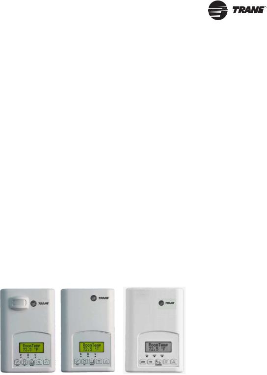
The Trane Communicating Thermostats are available for heat pump, rooftop, and fan coil applications.
•X13511541010 and -2010 (Heat Pump and Rooftop)
These Trane Communicating Thermostats are BACnet MS/TP devices specifically designed for single stage and multi-stage control of heating/cooling equipment such as rooftop and selfcontained units. The products feature an intuitive, menu-driven, back-lit LCD display, which walks users through the programming steps, making the process extremely simple.
•X13511543010 (Fan Coil)
This Trane Communicating thermostat is specifically designed for fan coil control. The product features a backlit LCD display with dedicated function menu buttons for simple operation. Three additional inputs are also provided for monitoring and / or various advanced functions. All models feature configurable System and Fan button functions to meet a variety of applications.
Accurate temperature control is achieved due to the product’s PI proportional control algorithm, which virtually eliminates temperature offset associated with traditional, differential-based thermostats.
The Communicating Thermostats contain an SPST auxiliary switch that can be used to control lighting or auxiliary reheat. Three additional inputs are also provided for monitoring and / or various advanced functions.
The thermostats are also compatible with the occupancy sensor cover accessories. Thermostats equipped with an occupancy sensor cover provide advanced active occupancy logic, which will automatically switch occupancy levels from Occupied to Unoccupied as required by local activity being present or not. This advanced occupancy functionality provides advantageous energy savings during occupied hours without sacrificing occupant comfort.
BAS-SVP10A-EN |
5 |

Overview
Related Documents
See the following documents for Communicating Thermostat installation and configuration information.
•Trane Communicating Thermostats for Heat Pump Control User Guide (BAS-SVU10x-EN)
•Trane Communicating Thermostats for Rooftop Control User Guide (BAS-SVU11x-EN)
•Trane Communicating Thermostats for Fan Coil Control User Guide (BAS-SVU12x-EN) See the following documents for Tracer SC network integration information.
•Tracer™ SC System Controller Installation and Setup (BAS-SVX31x-EN)
•Tracer™ BACnet™ Terminator Installation (X39641151-01x)
•Unit Controller Wiring Guide For the Tracer SC™ System Controller (BAS-SVN03x-EN
Finally, see the following documents for information about equipment including fan coils, rooftop units, and heat pumps.
•Communicating Thermostats for Rooftop and Heat Pump Control Product Data Sheet (BAS-PRC064-EN)
•Communicating Thermostats for Fan Coil Control Product Data Sheet (BAS-PRC065-EN)
All these documents are available from your Trane distributor.
Planning Your Integration
Study the following information presented in the chapters of this guide as you plan the work:
•Communicating Thermostat BACnet objects (points) and their properties (ranges, values, and enumeration sets for points). (See “Summary of BACnet Objects,” p. 7. and “BACnet Object Properties,” p. 14.)
•Tips and considerations presented in “Additional Information and Considerations,” p. 29. If your network is managed by a Tracer SC, pay special attention to “Tracer SC Network Configuration,” p. 32.
•Wiring instructions in “Wiring Requirements for Communicating Thermostats,” p. 25.
•Available Graphical User Interface (GUI) objects that you can use in graphics presented in “Objects You Can Use in Site Graphics,” p. 23.
“How To” Information
The following “how to” questions are described or clarified either in this manual or in other documents cited in this table.
Question |
Information Location or Answer |
|
How do I set up alarming in Tracer SC? |
See the Tracer™ SC System Controller Installation and |
|
Setup Manual (BAS-SVX31x-EN) |
||
|
How do I set the MAC address of the Trane Communicating See “Default Device Name and Default Device ID,” p. 7. Thermostat? Also, see the appropriate User Guide listed in “Related
Documents” on this page.
How do I install a Trane Communicating Thermostat on the See “No automatic installation,” p. 32. Tracer SC link?
6 |
BAS-SVP10A-EN |
Summary of BACnet Objects
The Building Automation and Control Network (BACnet and ANSI/ASHRAE Standard 135-2004) protocol is a standard that allows building automation systems or components from different manufacturers to share information and control functions. BACnet provides building owners the capability to connect various types of building control systems or subsystems together for many uses. In addition, multiple vendors can use this protocol to share information for monitoring and supervisory control between systems and devices in a multi-vendor interconnected system.
The BACnet protocol identifies standard objects (data points) called BACnet objects. Each object has a defined list of properties that provide information about that object. BACnet also defines a number of standard application services that are used to access data and manipulate these objects and provides a client/server communication between devices.
Supported BACnet Services
The BACnet communicating thermostat meets all requirements for designation as an Application Specific Controller (B-ASC). The BACnet thermostat series supports the following BACnet Interoperability Building Blocks (BIBBs).
Table 1. BACnet Interoperability Building Blocks
Application Service |
Designation |
Data Sharing – Read Property - B |
DS-RP-B |
Data Sharing – Read Property Multiple - B |
DS-RPM-B |
Data Sharing – Write Property - B |
DS-WP-B |
Device Management - Device Communication Control - B DM-DCC-B |
|
Device Management – Dynamic Device Binding - B |
DM-DDB-B |
Device Management – Dynamic Object Binding - B |
DM-DOB-B |
Notes:
•The thermostat does not support seqmented requests or responses.
•Models X13511541010 and -2010—Time synchronization can be made through a network even if the thermostat does not support the full date. Therefore, the device cannot claim conformance to the DeviceManagement – TimeSynchronization - B (DM-TS-B) service. The device object does not have the Local_Time or Local_Date properties.
Default Device Name and Default Device ID
The Default Device Name is set to: TStat_EquipType_Trane_MAC where: EquipType is FanCoil, RTU, or HeatPump and MAC is the current MAC address of the device.
•The Device Name is changed if you change the device MAC address.
•The Device Name and Device ID properties are writable in the Device object. Both properties can be changed from any BACnet network management tool as long as the tool itself can write to these properties.
(X13511543010) Fan Coil Models
•Default Device ID is set to: 7300MAC where MAC is the current MAC address of the device that you set from the Installer Configuration Parameter menu on the Trane Communicating Thermostat.
•The Device ID changes if the device’s MAC address is changed. For example, when a fan coil communicating thermostat with a MAC address of 41 is connected to a network, its default Device Name will be TStat_FanCoil_Trane_41 and its default Device ID will be 730041.
BAS-SVP10A-EN |
7 |

Summary of BACnet Objects
(X13511541010 and -2010) Rooftop and Heat Pump Models
•Default Device ID is set to: 7600MAC where MAC is the current MAC address of the device.
•The device ID and the Device Name change if you change the device’s MAC address. For example, when a heat pump communicating thermostat with a MAC address of 63 is connected to a network, its default Device Name will be TStat_HeatPump_Trane_63 and its default Device ID will be 760063.
Fan Coil Objects
Table 2. Objects table for fan coils (X13511543010)
Object Name |
Type and Instance |
Object Property |
Room Temperature |
AV 7 |
Present_Value (R,W) |
|
|
|
Room Temp Override |
BV 8 |
Present_Value (R,W) |
|
|
|
Outdoor Temperature |
AV 9 |
Present_Value (R,W) |
|
|
|
Supply Temperature |
AI 12 |
Present_Value (R) |
|
|
|
AUX Command |
BV 14 |
Present_Value (R,W) |
|
|
|
Sequence of Operation |
MV 15 |
Present_Value (R,W) |
|
|
|
System Mode |
MV 16 |
Present_Value (R,W) |
|
|
|
Fan Mode |
MV 17 |
Present_Value (R,W) |
|
|
|
Occupancy Command |
MV 18 |
Present_Value (R,W) |
|
|
|
Keypad Lockout |
MV 19 |
Present_Value (R,W) |
|
|
|
|
|
|
Control Output |
GRP 20 |
Present_Value (R) |
|
|
|
PI Heating Demand |
AV 21 |
Present_Value (R) |
|
|
|
PI Cooling Demand |
AV 22 |
Present_Value (R) |
|
|
|
|
|
|
Controller Status |
GRP 24 |
Present_Value (R) |
|
|
|
AUX Status |
BI 25 |
Present_Value (R) |
|
|
|
Heating Valve Status |
MV 26 |
Present_Value (R) |
|
|
|
Cooling Valve Status |
MV 27 |
Present_Value (R) |
|
|
|
Fan Status |
MV 28 |
Present_Value (R) |
|
|
|
BI 1 Status |
BI 29 |
Present_Value (R) |
|
|
|
BI 2 Status |
BI 30 |
Present_Value (R) |
|
|
|
UI 3 Status |
BI 31 |
Present_Value (R) |
|
|
|
Local Motion |
BI 32 |
Present_Value (R) |
|
|
|
Effective Occupancy |
MV 33 |
Present_Value (R) |
|
|
|
|
|
|
Controller Alarms |
GRP 34 |
Present_Value (R) |
|
|
|
Window Alarm |
BI 35 |
Present_Value (R) |
|
|
|
Filter Alarm |
BI 36 |
Present_Value (R) |
|
|
|
Service Alarm |
BI 37 |
Present_Value (R) |
|
|
|
|
|
|
Temperature Setpoints |
GRP 38 |
Present_Value (R) |
|
|
|
Occupied Heat Setpoint |
AV 39 |
Present_Value (R,W) |
|
|
|
Occupied Cool Setpoint |
AV 40 |
Present_Value (R,W) |
|
|
|
Stand-by Heat Setpoint |
AV 41 |
Present_Value (R,W) |
|
|
|
Stand-by Cool Setpoint |
AV 42 |
Present_Value (R,W) |
|
|
|
8 |
BAS-SVP10A-EN |

Summary of BACnet Objects
Table 2. Objects table for fan coils (X13511543010) (continued)
Object Name |
Type and Instance |
Object Property |
Unoccupied Heat Setpoint |
AV 43 |
Present_Value (R,W) |
|
|
|
Unoccupied Cool Setpoint |
AV 44 |
Present_Value (R,W) |
|
|
|
|
|
|
General Options 1 |
GRP 45 |
Present_Value (R) |
|
|
|
BI 1 Configuration |
MV 46 |
Present_Value (R,W) |
|
|
|
BI 2 Configuration |
MV 47 |
Present_Value (R,W) |
|
|
|
UI 3 configuration |
MV 48 |
Present_Value (R,W) |
|
|
|
Menu Scroll |
BV 49 |
Present_Value (R,W) |
|
|
|
Auto Mode Enable |
BV 50 |
Present_Value (R,W) |
|
|
|
Temperature Scale |
BV 51 |
Present_Value (R,W) |
|
|
|
Pipe Number |
MV 52 |
Present_Value (R,W) |
|
|
|
AUX Configuration |
MV 54 |
Present_Value (R,W) |
|
|
|
|
|
|
General Options 2 |
GRP 55 |
Present_Value (R) |
|
|
|
Password Value |
AV 56 |
Present_Value (R,W) |
|
|
|
Fan Mode Sequence |
MV 58 |
Present_Value (R,W) |
|
|
|
Heating Setpoint Limit |
AV 58 |
Present_Value (R,W) |
|
|
|
Cooling Setpoint Limit |
AV 59 |
Present_Value (R,W) |
|
|
|
Setpoint Type |
BV 60 |
Present_Value (R,W) |
|
|
|
Setpoint Function |
BV 61 |
Present_Value (R,W) |
|
|
|
Temporary Occupancy Time |
MV 62 |
Present_Value (R,W) |
|
|
|
Deadband |
AV 63 |
Present_Value (R,W) |
|
|
|
Reheat Time Base |
BV 64 |
Present_Value (R,W) |
|
|
|
Proportional Band |
MV 65 |
Present_Value (R,W) |
|
|
|
Auto Fan |
BV 66 |
Present_Value (R,W) |
|
|
|
Stand-by Time |
AV 67 |
Present_Value (R,W) |
|
|
|
Unoccupied Time |
AV 68 |
Present_Value (R,W) |
|
|
|
|
|
|
Output Configuration Options |
GRP 74 |
Present_Value (R) |
|
|
|
Control Type |
BV 75 |
Present_Value (R,W) |
|
|
|
Floating Motor Timing |
MV 76 |
Present_Value (R,W) |
|
|
|
On Off Control CPH |
MV 77 |
Present_Value (R,W) |
|
|
|
BAS-SVP10A-EN |
9 |

Summary of BACnet Objects
Rooftop and Heat Pump Objects
Table 3. Rooftop and heat pump ungrouped objects
|
|
|
|
|
Dehumidifi- |
|
|
Type and |
|
Rooftop |
Heat Pump |
cation |
|
Object Name |
Instance |
Object Property |
-1010 |
-2010 |
-1050 |
|
Room Temperature |
AV 7 |
Present_Value (R,W) |
√ |
√ |
√ |
|
|
|
|
|
|
|
|
Room Temp Override |
BV 8 |
Present_Value (R,W) |
√ |
√ |
√ |
|
|
|
|
|
|
|
|
Outdoor Temperature |
AV 9 |
Present_Value (R,W) |
√ |
√ |
√ |
|
|
|
|
|
|
|
|
Outdoor Temp Override |
BV 10 |
Present_Value (R,W) |
√ |
√ |
√ |
|
|
|
|
|
|
|
|
Room Humidity |
AV 11 |
Present_Value (R) |
|
|
√ |
|
|
|
|
|
|
|
|
Occupancy Command |
MV 12 |
Present_Value (R,W) |
√ |
√ |
√ |
|
|
|
|
|
|
|
|
System Mode HP |
MV 13 |
Present_Value (R,W) |
|
√ |
|
|
|
|
|
|
|
|
|
System Mode RTU |
MV 14 |
Present_Value (R,W) |
√ |
|
√ |
|
|
|
|
|
|
|
|
Fan Mode |
MV 15 |
Present_Value (R,W) |
√ |
√ |
√ |
|
|
|
|
|
|
|
|
Supply Temp |
AI 16 |
Present_Value (R) |
√ |
√ |
|
|
|
|
|
|
|
|
|
Supply RH |
AV 17 |
Present_Value (R) |
|
|
√ |
|
|
|
|
|
|
|
|
Keypad Lockout |
MV 18 |
Present_Value (R,W) |
√ |
√ |
√ |
|
|
|
|
|
|
|
|
Control Output |
GR 19 |
Present_Value (R) |
√ |
|
√ |
|
|
|
|
|
|
|
|
PI Heating Demand |
AV 20 |
Present_Value (R) |
√ |
√ |
√ |
|
|
|
|
|
|
|
|
PI Cooling Demand |
AV 21 |
Present_Value (R) |
√ |
√ |
√ |
|
|
|
|
|
|
|
|
Economizer Output |
AV 22 |
Present_Value (R) |
√ |
|
|
|
|
|
|
|
|
|
|
Controller Status |
GRP 23 |
Present_Value (R) |
√ |
|
√ |
|
|
|
|
|
|
|
|
AUX |
BI 24 |
Present_Value (R) |
√ |
√ |
√ |
|
|
|
|
|
|
|
|
G Fan |
BI 25 |
Present_Value (R) |
√ |
√ |
√ |
|
|
|
|
|
|
|
|
Y1 Cool |
BI 26 |
Present_Value (R) |
√ |
√ |
√ |
|
|
|
|
|
|
|
|
Y2 Cool |
BI 27 |
Present_Value (R) |
|
√ |
√ |
|
|
|
|
|
|
|
|
W1 Heat |
BI 28 |
Present_Value (R) |
√ |
√ |
√ |
|
|
|
|
|
|
|
|
W2 Heat |
BI 29 |
Present_Value (R) |
√ |
|
√ |
|
|
|
|
|
|
|
|
Reversing Valve |
BI 30 |
Present_Value (R) |
|
√ |
|
|
|
|
|
|
|
|
|
DI 1 Status |
BI 31 |
Present_Value (R) |
√ |
√ |
√ |
|
|
|
|
|
|
|
|
DI 2 Status |
BI 32 |
Present_Value (R) |
√ |
√ |
|
|
|
|
|
|
|
|
|
Local Motion |
BI 33 |
Present_Value (R) |
√ |
√ |
√ |
|
|
|
|
|
|
|
|
Effective Occupancy |
MV 34 |
Present_Value (R) |
√ |
√ |
√ |
|
|
|
|
|
|
|
|
Controller Alarms |
GRP 35 |
Present_Value (R) |
|
|
√ |
|
|
|
|
|
|
|
|
Frost Alarm |
BI 36 |
Present_Value (R) |
√ |
√ |
√ |
|
|
|
|
|
|
|
|
Filter Alarm |
BI 38 |
Present_Value (R) |
√ |
√ |
√ |
|
|
|
|
|
|
|
|
Service Alarm |
BI 39 |
Present_Value (R) |
√ |
√ |
√ |
|
|
|
|
|
|
|
|
Fan Lock Alarm |
BI 40 |
Present_Value (R) |
√ |
√ |
√ |
|
|
|
|
|
|
|
|
Temperature Setpoints |
GRP 41 |
Present_Value (R) |
√ |
√ |
√ |
|
|
|
|
|
|
|
|
Occupied Heat Setpoint |
AV 42 |
Present_Value (R,W) |
√ |
√ |
√ |
|
|
|
|
|
|
|
|
Occupied Cool Setpoint |
AV 43 |
Present_Value (R,W) |
√ |
√ |
√ |
|
|
|
|
|
|
|
|
Unoccupied Heat Setpoint |
AV 44 |
Present_Value (R,W) |
√ |
√ |
√ |
|
|
|
|
|
|
|
|
Unoccupied Cool Setpoint |
AV 45 |
Present_Value (R,W) |
√ |
√ |
√ |
|
|
|
|
|
|
|
|
General Options 1- |
GRP 46 |
Present_Value (R) |
√ |
√ |
√ |
|
|
|
|
|
|
|
|
Temperature Scale |
BV 47 |
Present_Value (R,W) |
√ |
√ |
√ |
|
|
|
|
|
|
|
|
Heating Setpoint Limit |
AV 48 |
Present_Value (R,W) |
√ |
√ |
√ |
|
|
|
|
|
|
|
|
Cooling Setpoint Limit |
AV 49 |
Present_Value (R,W) |
√ |
√ |
√ |
|
|
|
|
|
|
|
|
Heating Lockout |
AV 50 |
Present_Value (R,W) |
√ |
√ |
√ |
|
Temperature |
||||||
|
|
|
|
|
||
|
|
|
|
|
|
|
Cooling Lockout |
AV 51 |
Present_Value (R,W) |
√ |
√ |
√ |
|
Temperature |
||||||
|
|
|
|
|
||
|
|
|
|
|
|
|
Deadband |
AV 52 |
Present_Value (R,W) |
√ |
√ |
√ |
|
|
|
|
|
|
|
|
Heating CPH |
MV 53 |
Present_Value (R,W) |
√ |
√ |
√ |
|
|
|
|
|
|
|
10 |
BAS-SVP10A-EN |
Summary of BACnet Objects
Table 3. Rooftop and heat pump ungrouped objects
|
|
|
|
|
Dehumidifi- |
|
|
Type and |
|
Rooftop |
Heat Pump |
cation |
|
Object Name |
Instance |
Object Property |
-1010 |
-2010 |
-1050 |
|
Cooling CPH |
MV 54 |
Present_Value (R,W) |
√ |
√ |
√ |
|
|
|
|
|
|
|
|
Frost Protection |
BV 55 |
Present_Value (R,W) |
√ |
√ |
√ |
|
|
|
|
|
|
|
|
Aux Contact |
BV 56 |
Present_Value (R,W) |
√ |
√ |
√ |
|
|
|
|
|
|
|
|
Menu Scroll |
BV 57 |
Present_Value (R,W) |
√ |
√ |
√ |
|
|
|
|
|
|
|
|
General Options 2- |
GRP 58 |
Present_Value (R) |
√ |
√ |
√ |
|
|
|
|
|
|
|
|
Password Value |
AV 59 |
Present_Value (R,W) |
√ |
√ |
√ |
|
|
|
|
|
|
|
|
Power-up Delay |
AV 60 |
Present_Value (R,W) |
√ |
√ |
√ |
|
|
|
|
|
|
|
|
Temporary Occupancy |
MV 61 |
Present_Value (R,W) |
√ |
√ |
√ |
|
Time |
||||||
|
|
|
|
|
||
|
|
|
|
|
|
|
Fan Control |
BV 62 |
Present_Value (R,W) |
√ |
√ |
√ |
|
|
|
|
|
|
|
|
Anticycle |
MV 63 |
Present_Value (R,W) |
√ |
√ |
√ |
|
|
|
|
|
|
|
|
Fan Purge Delay |
BV 64 |
Present_Value (R,W) |
√ |
√ |
√ |
|
|
|
|
|
|
|
|
DI 1 Configuration |
MV 65 |
Present_Value (R,W) |
√ |
√ |
√ |
|
|
|
|
|
|
|
|
DI 2 Configuration |
MV 66 |
Present_Value (R,W) |
√ |
√ |
|
|
|
|
|
|
|
|
|
Proportional Band |
MV 67 |
Present_Value (R,W) |
√ |
√ |
√ |
|
|
|
|
|
|
|
|
Unoccupied Time |
AV 68 |
Present_Value (R,W) |
√ |
√ |
√ |
|
|
|
|
|
|
|
|
Stages Configuration |
GRP 72 |
Present_Value (R) |
|
|
√ |
|
Options |
|
|
||||
|
|
|
|
|
||
|
|
|
|
|
|
|
Heating Stages |
MV 73 |
Present_Value (R,W) |
√ |
|
√ |
|
|
|
|
|
|
|
|
Cooling Stages |
MV 74 |
Present_Value (R,W) |
√ |
|
√ |
|
|
|
|
|
|
|
|
Heatpump Stages |
MV 75 |
Present_Value (R,W) |
|
√ |
|
|
|
|
|
|
|
|
|
Economizer Model |
GRP 76 |
Present_Value (R) |
√ |
|
|
|
Configuration Options |
|
|
||||
|
|
|
|
|
||
|
|
|
|
|
|
|
Economizer Changeover |
AV 77 |
Present_Value (R,W) |
√ |
|
|
|
Setpoint |
|
|
||||
|
|
|
|
|
||
|
|
|
|
|
|
|
Economizer Minimum |
AV 78 |
Present_Value (R,W) |
√ |
|
|
|
Position |
|
|
||||
|
|
|
|
|
||
|
|
|
|
|
|
|
Mechanical Cooling |
BV 79 |
Present_Value (R,W) |
√ |
|
|
|
Enabled |
|
|
||||
|
|
|
|
|
||
|
|
|
|
|
|
|
Mixed Air Setpoint |
AV 80 |
Present_Value (R,W) |
√ |
|
|
|
|
|
|
|
|
|
|
Heatpump Model |
GRP 81 |
Present_Value (R) |
|
√ |
√ |
|
Configuration Options |
|
|||||
|
|
|
|
|||
|
|
|
|
|
|
|
High Balance Point |
AV 82 |
Present_Value (R,W) |
|
√ |
√ |
|
|
|
|
|
|
|
|
Low Balance Point |
AV 83 |
Present_Value (R,W) |
|
√ |
√ |
|
|
|
|
|
|
|
|
Comfort Mode |
BV 84 |
Present_Value (R,W) |
|
√ |
√ |
|
|
|
|
|
|
|
|
Reversing Valve |
BV 85 |
Present_Value (R,W) |
|
√ |
|
|
Configuration |
|
|
||||
|
|
|
|
|
||
|
|
|
|
|
|
|
Compressor Interlock |
BV 86 |
Present_Value (R,W) |
|
√ |
|
|
|
|
|
|
|
|
|
Dehumidification Model |
GRP 87 |
Present_Value (R) |
|
|
√ |
|
Configuration Options |
|
|
|
|
|
|
RH Display |
BV 88 |
Present_Value (R,W) |
|
|
√ |
|
|
|
|
|
|
|
|
Dehumidification RH |
AV 89 |
Present_Value (R,W) |
|
|
√ |
|
Setpoint |
|
|
||||
|
|
|
|
|
||
|
|
|
|
|
|
|
Dehumidification |
AV 90 |
Present_Value (R,W) |
|
|
√ |
|
Hysterisys |
|
|
||||
|
|
|
|
|
||
|
|
|
|
|
|
|
Dehumidification Low OA |
AV 91 |
Present_Value (R,W) |
|
|
√ |
|
Lockout |
|
|
||||
|
|
|
|
|
||
|
|
|
|
|
|
|
Dehumidification Lockout |
BV 92 |
Present_Value (R,W) |
|
|
√ |
|
Functions |
|
|
||||
|
|
|
|
|
||
|
|
|
|
|
|
|
Dehumidification Output |
BI 93 |
Present_Value (R) |
|
|
√ |
|
Status |
|
|
||||
|
|
|
|
|
||
|
|
|
|
|
|
|
Humidification Model |
GRP 94 |
Present_Value (R) |
|
|
√ |
|
Configuration Options |
|
|
||||
|
|
|
|
|
||
|
|
|
|
|
|
|
Humidification RH Setpoint |
AV 95 |
Present_Value (R,W) |
|
|
√ |
|
|
|
|
|
|
|
BAS-SVP10A-EN |
11 |

Summary of BACnet Objects
Table 3. Rooftop and heat pump ungrouped objects
|
|
|
|
|
Dehumidifi- |
|
Type and |
|
Rooftop |
Heat Pump |
cation |
Object Name |
Instance |
Object Property |
-1010 |
-2010 |
-1050 |
Eff (Effective) Reset |
|
|
|
|
|
Humidification RH Spt |
AV 96 |
Present_Value (R) |
|
|
√ |
(Setpoint) |
|
|
|
|
|
|
|
|
|
|
|
Humidification High Limit |
AV 97 |
Present_Value (R,W) |
|
|
√ |
Spt (Setpoint) |
|
|
|||
|
|
|
|
|
|
|
|
|
|
|
|
Low RH Setpoint |
AV 98 |
Present_Value (R,W) |
|
|
√ |
|
|
|
|
|
|
Low Temp Reset RH |
AV 99 |
Present_Value (R,W) |
|
|
√ |
Setpoint |
|
|
|||
|
|
|
|
|
|
|
|
|
|
|
|
High Temp Reset RH |
AV 100 |
Present_Value (R,W) |
|
|
√ |
Setpoint |
|
|
|||
|
|
|
|
|
|
|
|
|
|
|
|
Humidifier Output |
AV 101 |
Present_Value (R) |
|
|
√ |
|
|
|
|
|
|
Standard Object Types Supported
Table 4. Standard object types supported
|
|
|
|
Optional |
|
|
Supported |
Dynamically |
Dynamically |
Properties |
|
Object Type |
Objects |
Creatable |
Deletable |
Supported |
WritableProperties |
Analog Input |
|
|
|
Reliability |
Out_of_Service |
|
|
|
|
|
|
Analog Value |
|
|
|
Reliability |
Present_Value (a,b,e) |
|
|
|
|
|
Out_of_Service (a,e) |
|
|
|
|
|
Object_Name (c ,f) |
|
|
|
|
|
|
Binary Input |
|
|
|
Reliability |
Out_of_Service |
|
|
|
|
Active_Text |
|
|
|
|
|
Inactive_Text |
|
|
|
|
|
|
|
Binary Value |
|
|
|
Reliability |
Present_Value |
|
|
|
|
Active_Text |
Out_of_Service |
|
|
|
|
Inactive_Text |
|
|
|
|
|
|
|
Device |
|
|
|
Max_Master |
Object_Identifier |
|
|
|
|
Max_Info_frames |
Object_name |
|
|
|
|
|
Max_Master |
|
|
|
|
|
|
Group |
|
|
|
N/A |
N/A |
|
|
|
|
|
|
Multi-state Value |
|
|
|
Reliability |
Present_Value (d) |
|
|
|
|
States_Text |
Out_of_Service (d) |
|
|
|
|
|
|
Schedule |
|
|
|
Weekly_schedule |
Present_Value |
(Rooftop and heat |
|
|
|
|
Weekly_Schedule |
pump only) |
|
|
|
|
|
|
|
|
|
|
|
Footnotes for fan coils:
a : Present_Value and Out_of_Service properties are writable for every AV objects except PI Heating Demand (AV21) and PI Cooling Demand (AV22).
b : Present_Value property for Room Temperature (AV7) and Room Humidity (AV10) is writable only if Room Temp Override (BV8) is enabled and Room Humidity Override (BV11) is enabled respectively.
12 |
BAS-SVP10A-EN |

Summary of BACnet Objects
c : Object_Name property is writable only for Room Temperature (AV7).
d : Present_Value and Out_of_Service properties are writable for every MV objects except Heating Valve Status (MV26), Cooling Valve Status (MV27), Fan Status (MV28), and Effective Occupancy (MV33)
Footnotes for rooftop units and heat pumps
e:The following AV’s are defined as read only. When Out_of_Service properties is set to true, the Present_Value, if written, is not derived to the application level of the thermostat.
-Room Humidity (AV11)
-PI Heating Demand (AV20)
-PI Cooling Demand (AV21)
-Economizer Output (AV22)
-Eff Reset Humidification RH Spt (AV96)
-Humidifier Output (AV101)
f:Object_Name property is writable for 1 object only: Room_Temperature (AV7).
List of Proprietary Properties
Table 5. Proprietary Properties
Property Name |
ID |
BACnet Data Type |
Description |
Major_Version |
1000 |
CharacterString |
The version number of the BACnet communications |
|
|
|
module. This the hardware version number |
|
|
|
|
MS/TP_Address |
1001 |
Unsigned |
Display the MAC layer address of the module |
|
|
|
|
MS/TP_Baud_Rate |
1002 |
Unsigned |
Display the communication baud rate of the module |
|
|
|
|
Sensor_Offset |
1005 |
REAL |
Display the temperature or humidity calibration value. The |
|
|
|
range is –5.0 deg F to 5.0 deg F for a temperature and – |
|
|
|
15% to 15% for humidity. |
|
|
|
|
Configuration Objects for Fan Coils
The following objects and group objects listed in Table 2, p. 8 should be typically used for configuration purposes:
•General Options 1 Group GRP 45 and its complete list of objects
•General Options 2 Group GRP 55 and its complete list of objects
•Output Configuration Options Group GRP 74 and its complete list of objects
Configuration Objects for Rooftop and Heat Pump Units
The following objects and group objects listed in Table 2, p. 8 should be typically used for configuration purposes:
•General Options 1 Group GRP 46 and its complete list of objects
•General Options 2 Group GRP 58 and its complete list of objects
•Programmable Model Configuration Options Group GRP 69 and its complete list of objects
•Stages Configuration Options Group GRP 72 and its complete list of objects;
•Economizer Model Configuration Option Group GRP 76 and its complete list of objects;
•Heatpump Model Configuration Option Group GRP 81 and its complete list of objects;
•Dehumidification Model Configuration Option Group GRP 87 and its complete list of objects;
•Humidification Model Configuration Option Group GRP 94 and its complete list of objects;
BAS-SVP10A-EN |
13 |

BACnet Object Properties
This section lists ranges, enumerations, and values for the set of Communicating Thermostat objects.
Fan Coil Object Properties
Table 6. List of property value range restrictions
|
Object Type and |
Minimum Range |
Maximum Range |
|
|
Object Name |
Instance |
Value |
Value |
Default Value |
|
Room Temperature |
AV 7 |
-39.9°F (-40°C) |
121.9°F (50°C) |
N/A |
|
|
|
|
|
|
|
Outdoor Temperature |
AV 9 |
-39°F (-40°C) |
121.9°F (50°C) |
N/A |
|
|
|
|
|
|
|
Room Humidity |
AV 10 |
5% |
90% |
N/A |
|
|
|
|
|
|
|
Supply Temperature |
AI 12 |
-39.9°F (-40°C) |
121.9°F (50°C) |
N/A |
|
|
|
|
|
|
|
PI Heating demand |
AV 21 |
0% |
100% |
0% |
|
|
|
|
|
|
|
PI Cooling demand |
AV 22 |
0% |
100% |
0% |
|
|
|
|
|
|
|
Occupied Heat |
AV 39 |
40°F (4.5°C) |
90°F (32°C) |
72°F (22°C) |
|
Setpoint |
|||||
|
|
|
|
||
|
|
|
|
|
|
Occupied Cool |
AV 40 |
54°F (12°C) |
100°F (37.5°C) |
74°F (24°C) |
|
Setpoint |
|||||
|
|
|
|
||
|
|
|
|
|
|
Stand-by Heat |
AV 41 |
40°F (4.5°C) |
90°F (32°C) |
72°F (22°C) |
|
Setpoint |
|||||
|
|
|
|
||
|
|
|
|
|
|
Stand-by Cool |
AV 42 |
54°F (12°C) |
100°F (37.5°C) |
74°F (24°C) |
|
Setpoint |
|||||
|
|
|
|
||
|
|
|
|
|
|
Unoccupied Heat |
AV 43 |
40°F (4.5°C) |
90°F (32°C) |
62°F (16.5°C) |
|
Setpoint |
|||||
|
|
|
|
||
|
|
|
|
|
|
Unoccupied Cool |
AV 44 |
54°F (12°C) |
100°F (37.5°C) |
80°F (26.5°C) |
|
Setpoint |
|||||
|
|
|
|
||
|
|
|
|
|
|
Password Value |
AV 56 |
0 |
1000 |
0 |
|
|
|
|
|
|
|
Heating Setpoint Limit |
AV 58 |
40°F (4.5°C) |
90°F (32°C) |
90°F (32°C) |
|
|
|
|
|
|
|
Cooling Setpoint Limit |
AV 59 |
54°F (12°C) |
100°F (37.5°C) |
54°F (12°C) |
|
|
|
|
|
|
|
Deadband |
AV 63 |
2°F (1°C) |
5°F (2.5°C) |
2°F (1°C) |
|
|
|
|
|
|
|
Stand-by Time |
AV 67 |
0.5 Hours |
24.0 Hours |
0.5 Hours |
|
|
|
|
|
|
|
Unoccupied Time |
AV 68 |
0.0 Hours |
24.0 Hours |
0.0 Hours |
|
|
|
|
|
|
|
RH Setpoint |
AV 45 |
30% |
100% |
50% |
|
|
|
|
|
|
|
Dehumidification |
AV 46 |
2% |
20% |
5% |
|
Hysterisys |
|||||
|
|
|
|
||
|
|
|
|
|
|
Dehumidification MAX |
AV 47 |
20% |
100% |
100% |
|
cooling |
|||||
|
|
|
|
||
|
|
|
|
|
Table 7. List of property enumeration sets for BV objects and BI objects
|
Object Type and |
|
|
|
|
Object Name |
instance |
Inactive_Text |
Active_Text |
Default value |
|
Room Temp Override |
BV 8 |
Normal |
Override |
Normal |
|
|
|
|
|
|
|
Room Humidity |
BV 11 |
Normal |
Override |
Normal |
|
Override |
|||||
|
|
|
|
||
|
|
|
|
|
|
Dehumidification |
BV 13 |
Disabled |
Enabled |
Enabled |
|
Lockout |
|||||
|
|
|
|
||
|
|
|
|
|
|
AUX Command |
BV 14 |
Off |
On |
Off |
|
|
|
|
|
|
|
Dehumidification |
BI 23 |
Off |
On |
Off |
|
Status |
|||||
|
|
|
|
||
|
|
|
|
|
|
Aux Status |
BI 25 |
Off |
On |
Off |
|
|
|
|
|
|
|
BI 1 Status |
BI 29 |
Deactivated |
Activated |
Deactivated |
|
|
|
|
|
|
|
BI 2 Status |
BI 30 |
Deactivated |
Activated |
Deactivated |
|
|
|
|
|
|
|
UI 3 Status(*) |
BI 31 |
Deactivated |
Activated |
Deactivated |
|
|
|
|
|
|
|
Local Motion |
BI 32 |
No Motion |
Motion |
No Motion |
|
|
|
|
|
|
|
Window Alarm |
BI 35 |
Off |
On |
Off |
|
|
|
|
|
|
14 |
BAS-SVP10A-EN |

BACnet Object Properties
Table 7. List of property enumeration sets for BV objects and BI objects (continued)
|
Object Type and |
|
|
|
|
Object Name |
instance |
Inactive_Text |
Active_Text |
Default value |
|
Filter Alarm |
BI 36 |
Off |
On |
Off |
|
|
|
|
|
|
|
Service Alarm |
BI 37 |
Off |
On |
Off |
|
|
|
|
|
|
|
Menu Scroll |
BV 49 |
No Scroll |
Scroll Active |
Scroll Active |
|
|
|
|
|
|
|
Auto Mode Enable |
BV 50 |
Disabled |
Enabled |
Enabled |
|
|
|
|
|
|
|
Temperature Scale |
BV 51 |
°C |
°F |
°F |
|
|
|
|
|
|
|
Setpoint Type |
BV 60 |
Permanent |
Temporary |
Permanent |
|
|
|
|
|
|
|
Setpoint Function |
BV 61 |
Dual Setpoints |
Attached Setpoints |
Dual Setpoints |
|
|
|
|
|
|
|
Reheat Time Base |
BV 64 |
15 minutes |
10 seconds |
15 minutes |
|
|
|
|
|
|
|
Auto Fan |
BV 66 |
Auto Speed |
Auto Speed / Auto |
Auto Speed |
|
Demand |
|||||
|
|
|
|
||
|
|
|
|
|
|
RH Display |
BV 70 |
Disabled |
Enabled |
Disabled |
|
|
|
|
|
|
|
Control Type |
BV 75 |
On/Off |
Floating |
On/Off |
|
|
|
|
|
|
|
Direct/ Reverse Acting |
BV 78 |
Direct Acting |
Reverse Acting |
Direst Acting |
|
|
|
|
|
|
*This object will be linked to the value of the ‘UI 3 Configuration’ object. When the ‘UI 3 Configuration’ object value is 0, 3 or 4, the value will be set to ‘Deactivated.’
Table 8. List of property enumeration sets for MV objects
Object Name |
Object ID |
BACnet Index |
Text |
Default value |
|
|
|
1 |
Cooling Only |
|
|
|
|
|
|
|
|
|
|
2 |
Heating Only |
|
|
|
|
|
|
|
|
Sequence of |
MV 15 |
3 |
Cooling & Reheat |
Heating Only |
|
Operation |
|
|
|
||
|
4 |
Heating & Reheat |
|||
|
|
||||
|
|
|
|
|
|
|
|
5 |
Cool/Heat4P |
|
|
|
|
|
|
|
|
|
|
6 |
Cool/Heat4P&Reht |
|
|
|
|
|
|
|
|
|
|
1 |
Off |
|
|
|
|
|
|
|
|
System Mode |
MV 16 |
2 |
Auto |
Table Note 2 |
|
Table Note 1 |
|
|
|
||
|
3 |
Cool |
|||
|
|
||||
|
|
|
|
|
|
|
|
4 |
Heat |
|
|
|
|
|
|
|
|
Fan Mode |
MV 17 |
1, 2, 3 or 4 |
Table Note 4 |
Table Note 5 |
|
Table Note 3 |
|||||
|
|
|
|
||
|
|
|
|
|
|
|
MV 18 |
1 |
Local Occupancy |
Depends on network |
|
Occupancy Command |
|
|
|
||
|
2 |
Occupied |
|||
|
command |
||||
|
|
|
|
||
|
|
3 |
Unoccupied |
|
|
|
|
|
|
|
|
|
|
1 |
Level 0 |
|
|
|
|
|
|
|
|
|
|
2 |
Level 1 |
|
|
|
|
|
|
|
|
Keypad Lockout |
MV 19 |
3 |
Level 2 |
Level 0 |
|
|
|
||||
4 |
Level 3 |
||||
|
|
|
|||
|
|
|
|
|
|
|
|
5 |
Level 4 |
|
|
|
|
|
|
|
|
|
|
6 |
Level 5 |
|
|
|
|
|
|
|
Table Notes:
1Enumeration sets for MV16 depends on Sequence of Operation (MV15) value upon device discovery. If required enumeration is not present, set MV15 to desired value and rediscover MV16 object. Available enumeration will now reflect required configuration.
2Default value of MV16 depends on MV15 value upon device discovery. (See Table 9.)
BAS-SVP10A-EN |
15 |
Loading...