


 Loading...
Product Catalog
Trane Advantage™ VRF Mini Outdoor Unit
December 2013 |
VRF-PRC007-EN |

Table of Contents
VRF Mini Outdoor Unit . . . . . . . . . . . . . . . . . . . . . . . . . . . . . . . . . . . . . . . . . . . . . 3
Nomenclature . . . . . . . . . . . . . . . . . . . . . . . . . . . . . . . . . . . . . . . . . . . . . . . . . . 3
System Features . . . . . . . . . . . . . . . . . . . . . . . . . . . . . . . . . . . . . . . . . . . . . . . . 4
Indoor Units . . . . . . . . . . . . . . . . . . . . . . . . . . . . . . . . . . . . . . . . . . . . . . . . . . . . . . 5
Nomenclature . . . . . . . . . . . . . . . . . . . . . . . . . . . . . . . . . . . . . . . . . . . . . . . . . . |
5 |
Products . . . . . . . . . . . . . . . . . . . . . . . . . . . . . . . . . . . . . . . . . . . . . . . . . . . . . . . . . 6
Application Matrix . . . . . . . . . . . . . . . . . . . . . . . . . . . . . . . . . . . . . . . . . . . . . . . 6
Controls . . . . . . . . . . . . . . . . . . . . . . . . . . . . . . . . . . . . . . . . . . . . . . . . . . . . . . . 7
Accessories . . . . . . . . . . . . . . . . . . . . . . . . . . . . . . . . . . . . . . . . . . . . . . . . . . . . 8
Mini Outdoor Units . . . . . . . . . . . . . . . . . . . . . . . . . . . . . . . . . . . . . . . . . . . . . . . . 9
Product Specifications . . . . . . . . . . . . . . . . . . . . . . . . . . . . . . . . . . . . . . . . . . . 9
Operation Limit . . . . . . . . . . . . . . . . . . . . . . . . . . . . . . . . . . . . . . . . . . . . . . . . 10
Electrical Wiring Diagram . . . . . . . . . . . . . . . . . . . . . . . . . . . . . . . . . . . . . . . . 10
Heat Pump . . . . . . . . . . . . . . . . . . . . . . . . . . . . . . . . . . . . . . . . . . . . . . . . . . 10
Sound Levels . . . . . . . . . . . . . . . . . . . . . . . . . . . . . . . . . . . . . . . . . . . . . . . . . . 11
Sound Pressure Level . . . . . . . . . . . . . . . . . . . . . . . . . . . . . . . . . . . . . . . . . 11
NC Curves . . . . . . . . . . . . . . . . . . . . . . . . . . . . . . . . . . . . . . . . . . . . . . . . . . 11
Sound Power . . . . . . . . . . . . . . . . . . . . . . . . . . . . . . . . . . . . . . . . . . . . . . . . 12
NR Curves . . . . . . . . . . . . . . . . . . . . . . . . . . . . . . . . . . . . . . . . . . . . . . . . . . 12
Cycle Diagrams . . . . . . . . . . . . . . . . . . . . . . . . . . . . . . . . . . . . . . . . . . . . . . . . 13
Dimensional Drawings . . . . . . . . . . . . . . . . . . . . . . . . . . . . . . . . . . . . . . . . . . 14
Heat Pump . . . . . . . . . . . . . . . . . . . . . . . . . . . . . . . . . . . . . . . . . . . . . . . . . . 14
Capacity Tables . . . . . . . . . . . . . . . . . . . . . . . . . . . . . . . . . . . . . . . . . . . . . . . . 15
4TVH0036B100NB . . . . . . . . . . . . . . . . . . . . . . . . . . . . . . . . . . . . . . . . . . . . 15 4TVH0048B100NB . . . . . . . . . . . . . . . . . . . . . . . . . . . . . . . . . . . . . . . . . . . . 23 4TVH0053B100NB . . . . . . . . . . . . . . . . . . . . . . . . . . . . . . . . . . . . . . . . . . . . 27
Capacity Correction . . . . . . . . . . . . . . . . . . . . . . . . . . . . . . . . . . . . . . . . . . . . . 33
Capacity correction by distance . . . . . . . . . . . . . . . . . . . . . . . . . . . . . . . . . 33
Defrosting Correction Factor . . . . . . . . . . . . . . . . . . . . . . . . . . . . . . . . . . . 34
For Trane Advantage VRF indoor units, refer to VRF-PRC006-EN
For larger capacity Trane Advantage VRF outdoor units, refer to VRF-PRC008-EN
2 |
VRF-PRC007-EN |

VRF Mini Outdoor Unit
Nomenclature
4 |
T |
V |
H |
0 |
0 |
4 |
8 |
B |
1 |
0 |
0 |
N |
B |
1 |
2 |
3 |
4 |
5 |
6 |
7 |
8 |
9 |
10 |
11 |
12 |
13 |
14 |
Digit 1 — Refrigerant |
Digit 6, 7, 8 — Nominal Capacity |
|||||
4 |
= |
R-410a |
(Btu/h x 1,000) |
|||
Digit 2 — Brand Name |
036 |
= |
36,000 Btu/h |
|||
T |
= |
Trane |
048 |
= |
48,000 Btu/h |
|
053 |
= |
60,000 Btu/h |
||||
|
|
|
||||
Digit 3 — System Type |
072 |
= |
72,000 Btu/h |
|||
V |
= |
Variable Refrigerant Flow |
096 |
= |
96,000 Btu/h |
|
120 |
= |
120,000 Btu/h |
||||
Digit 4 — Functional Type |
||||||
144 |
= |
144,000 Btu/h |
||||
Outdoor Unit |
168 |
= |
168,000 Btu/h |
|||
(also see separate tab) |
192 |
= |
192,000 Btu/h |
|||
Digit 9 — Major Development |
||||||
H |
= Heat Pump, DC Inverter (VRF) |
|||||
R |
= Heat Recovery (3-pipe), DC |
Sequence |
||||
|
|
Inverter (VRF) |
B |
= |
Second Development Sequence |
|
Digit 5 — Special Application |
||||||
Digit 10 — Electric Power |
||||||
0 |
= |
Standard |
||||
Supply Characteristics |
||||||
|
|
|
1 |
= |
208~230/60/1 |
|
|
|
|
3 |
= |
208~230/60/3 |
|
|
|
|
4 |
= |
460/60/3 |
|
Digit 11 — Reserved for Future Use
0 = Not currently used
Digit 12 — Reserved for Future Use
0 = Not currently used
Digit 13 |
— Region of Sale |
||
N |
= |
North America (UL or ETL) |
|
Digit 14 |
— Minor Design |
||
Sequence |
|||
B |
= |
Second Design Sequence |
|
VRF-PRC007-EN |
3 |

VRF Mini Outdoor Units
Product Features
•Single phase power is suitable for residential and light commercial applications
•Heat pump design delivers either cooling or heating to the connected zones
•Space saving footprint - 13" depth allows installation in almost any location
•Inverter rotary compressor has been rigorously tested for high reliability and performance
•All major components can be accessed through the front of the unit, simplifying maintenance
•Up to 9 indoor units can be connected, with a wide variety of capacities and configurations available to meet most architectural design requirements
•Individual zone control meets the comfort requirements of each occupant
•Compatible with the same building controls as the larger capacity Trane Advantage VRF systems
4 |
VRF-PRC007-EN |

Indoor Units
Nomenclature
4 |
T |
V |
D |
0 |
0 |
1 |
8 |
B |
1 |
0 |
0 |
N |
B |
1 |
2 |
3 |
4 |
5 |
6 |
7 |
8 |
9 |
10 |
11 |
12 |
13 |
14 |
Digit 1 — Refrigerant |
Digit 5 — Reserved for Future |
|||||
4 = R-410a |
Use |
|
||||
Digit 2 — Brand Name |
0 |
= |
Not currently used |
|||
T |
= |
Trane |
Digit 6, 7, 8 — Nominal Capacity |
|||
Digit 3 — System Type |
(Btu/h x 1,000) |
|||||
007= |
7,000 Btu/h |
|||||
V |
= |
Variable Refrigerant Flow |
||||
009= |
9,000 Btu/h |
|||||
Digit 4 — Configuration Type |
||||||
012= |
12,000 Btu/h |
|||||
A |
= High Pressure Static Duct Type |
015= |
15,000 Btu/h |
|||
B |
= |
Mini 4-Way Cassette |
018= |
18,000 Btu/h |
||
C |
= |
4-Way Cassette |
024= |
24,000 Btu/h |
||
D |
= Mid Pressure Static Duct Type |
030= |
30,000 Btu/h |
|||
E |
= |
1-Way Cassette |
036= |
36,000 Btu/h |
||
L |
= Slim Duct Type (Low Pressure) |
048= |
48,000 Btu/h |
|||
X |
= |
Convertible Floor/Ceiling |
076= |
76,000 Btu/h |
||
W |
= |
High Wall Type |
096= |
96,000 Btu/h |
||
|
|
|
Digit 9 — Major Development |
|||
|
|
|
Sequence |
|||
|
|
|
B |
= |
Second Development Sequence |
|
|
|
|
Digit 10 — Electric Power |
|||
|
|
|
Supply Characteristics |
|||
|
|
|
1 |
= |
208~230/60/1 |
|
Digit 11 — Reserved for Future Use
0 = Not currently used
Digit 12 — Reserved for Future Use
0 = Not currently used
Digit 13 — Region of Sale
N = North America (UL or ETL)
Digit 14 — Minor Design
Sequence
B = Second Design Sequence
VRF-PRC007-EN |
5 |
Products
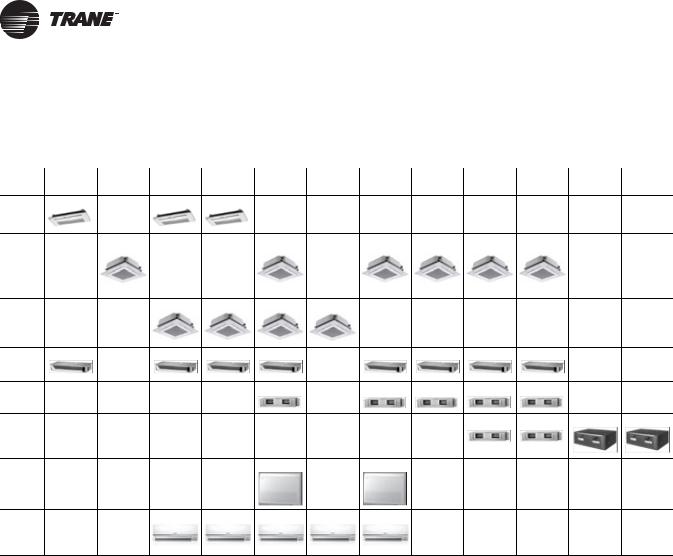
Application Matrix
Capacity |
7.5MBH 9.0MBH 9.5MBH 12MBH 18MBH 20MBH 24MBH 30MBH 36MBH 48MBH 76.8MBH 96MBH |
|
Type |
||
|
||
|
|
Slim 1 way
cassette
4 way cassette
Mini 4 way cassette (interior)
Slim duct
MSP duct
HSP duct
Ceiling
High Wall 
6 |
VRF-PRC007-EN |

Products
Controls
Family |
Description |
Trane Model Number |
|
|
|
|
|
|
VRF System Controller |
TVCTRLTIMD00A0 |
|
Integrated System |
|
|
|
VRF Enterprise Management Software |
TVCTRLTSTP3P00 |
||
Management |
|||
|
|
||
|
VRF Power Meter Interface Module |
TVCTRLTIMB16A0 |
|
|
|
|
|
Building Management |
VRF System Controller+BACnet |
TVCTRLTIMB17A0 |
|
|
|
||
System Gateways |
|
|
|
VRF System Controller+LONTalk |
TVCTRLTIMB18A0 |
||
|
|||
|
|
|
|
|
VRF Central On/Off Controller |
TVCTRLTCMA202D |
|
Centralized Control |
|
|
|
VRF System TouchScreen Control |
TVCTRLTCMA300T |
||
Systems |
|||
|
|
||
|
VRF Mode Select Switch |
TVCTRLTCMC2000 |
|
|
|
|
|
|
VRF Wireless Remote Control |
TVCTRLTRDH00UT |
|
|
|
|
|
Zone Controllers |
VRF Wired Remote Control |
TVCTRLTWRWE10T |
|
|
|
|
|
|
VRF Duct Signal Receiver & Wire |
TVCTRLTRKA10N0 |
|
|
|
|
|
Interface Modules |
VRF External Contact Interface Module |
TVCTRLTIMB14A0 |
|
|
|
|
|
Sensors |
VRF Ext. Room Temp Sensor |
TVCTRLTRWTA000 |
|
|
|
||
VRF Motion Sensor Mini 4Way |
MOTIONSEN4TVB |
||
|
|||
|
|
|
|
Commissioning and |
VRF Auto-Commissioning Tool |
TVCTRLTIMC1000 |
|
|
|
||
Utility Kits |
|
|
|
VRF Technician Utilities |
TVCTRLTIMC0300 |
||
|
|||
|
|
|
VRF-PRC007-EN |
7 |

Products
Accessories
Family |
Description |
Trane Model Number |
|
|
VRF Y-joint <51MBh |
4YDK1509B0051A |
|
|
|
|
|
|
VRF Y-joint 51-138MBh |
4YDK2512B0138A |
|
|
|
|
|
|
VRF Y-joint 138-160MBh |
4YDK2812B0160A |
|
|
|
|
|
Y- joint |
VRF Y-joint 160-240MBh |
4YDK2815B0240A |
|
|
|
|
|
|
VRF Y-joint 240-336MBh |
4YDK3419B0336A |
|
|
|
|
|
|
VRF Y-joint 336-468MBh |
4YDK4119B0468A |
|
|
|
|
|
|
VRF Y-joint >468MBh |
4YDK4422B0999A |
|
|
|
|
|
|
VRF Header Joint 4Units <160MBh |
4HJK2512B0159A |
|
|
|
|
|
Header Joint |
VRF Header Joint 8Units ≤240MBh |
4HJK3115B0241A |
|
|
|
|
|
|
VRF Header Joint 8Units >240MBh |
4HJK3819B0998A |
|
|
|
|
|
|
VRF EEV 1x 7-15.5& 1x 17-31MBh |
4EEVXDA24K132A |
|
|
|
|
|
|
VRF EEV Kit 2Unit 7-15.5MBh |
4EEVXDA24K200A |
|
|
|
|
|
|
VRF EEV Kit 2Unit 17-31MBh |
4EEVXDA32K200A |
|
|
|
|
|
EEV Kits |
VRF EEV 2x 7-15.5& 1x 17-31MBh |
4EEVXDA24K232A |
|
|
|
||
(For Wall-mounted & |
VRF EEV Kit 3Unit 7-15.5MBh |
4EEVXDA24K300A |
|
Ceiling indoor unit |
|
|
|
VRF EEV 1x 7-15.5& 2x 17-31MBh |
4EEVXDA32K224A |
||
|
|||
|
|
|
|
|
VRF EEV Kit 3Unit 17-31MBh |
4EEVXDA32K300A |
|
|
|
|
|
|
VRF EEV Kit 1Unit 7-15.5MBh |
4EEVEVA24SA000 |
|
|
|
|
|
|
VRF EEV Kit 1Unit 17-31MBh |
4EEVEVA32SA000 |
|
|
|
|
|
|
VRF AHU Kit 24-30MBh |
4EEVAKA40K1025 |
|
|
|
|
|
AHU Kit |
VRF AHU Kit 48-60MBh |
4EEVAKA40K1050 |
|
|
|
||
VRF AHU Kit 72-90MBh |
4EEVAKA64K1075 |
||
|
|||
|
|
|
|
|
VRF AHU Kit 96-112MBh |
4EEVAKA64K1100 |
|
|
|
|
|
|
VRF Drain Pump Slim Duct |
CONDPUMPXVLB01 |
|
|
|
|
|
|
VRF Drain Pump MSP 18/24MBh |
CONDPUMPXVMB01 |
|
|
|
|
|
DRAIN PUMP |
VRF Drain Pump MSP 30/36MBh |
CONDPUMPXVMB02 |
|
|
|
|
|
|
VRF Drain Pump MSP48/ HSP36-48MBh |
CONDPUMPXVDB01 |
|
|
|
|
|
|
VRF Drain Pump HSP 76.8/96MBh |
CONDPUMPXVHB01 |
|
|
|
|
|
|
VRF Cassette Panel Slim 1Way |
TVEPANPC1NUSET |
|
|
|
|
|
CASSETTE PANEL |
VRF Cassette Panel Sliding 1Way |
TVEPANPC1NUAET |
|
|
|
||
VRF Cassette Panel Mini 4Way |
TVEPANPC4SUSET |
||
|
|||
|
|
|
|
|
VRF Cassette Panel 4Way |
TVEPANPC4NUSET |
|
|
|
|
8 |
VRF-PRC007-EN |

Mini Outdoor Units
Product Specifications
208~230V Heat Pump Single Modules
Model Name |
|
|
|
4TVH0036B100NB |
4TVH0048B100NB |
4TVH0053B100NB |
||||||
Power Supply |
|
|
|
208~230/60/1 |
208~230/60/1 |
208~230/60/1 |
||||||
|
|
|
|
|
|
|
|
|
|
|||
|
Nominal Tons |
|
|
|
3.0 |
|
4.0 |
|
4.5 |
|||
|
|
|
|
|
|
|
|
|
|
|
|
|
|
System Type |
|
|
Ducted |
|
Non-Ducted |
Ducted |
|
Non-Ducted |
Ducted |
|
Non-Ducted |
|
|
|
|
|
|
|
|
|
|
|
|
|
|
|
Cooling |
Btu/h |
38,000 |
|
38,000 |
48,000 |
|
48,000 |
53,000 |
|
53,000 |
|
|
|
|
|
|
|
|
|
|
|
|
|
|
Capacity |
High Temp |
Btu/h |
42,000 |
|
42,000 |
54,000 |
|
54,000 |
61,000 |
|
61,000 |
|
Heating |
|
|
|
||||||||
Performance |
(Rated)1, 2 |
|
|
|
|
|
|
|
|
|
|
|
|
|
|
|
|
|
|
|
|
|
|
||
Low Temp |
Btu/h |
26,600 |
|
26,000 |
35,000 |
|
33,000 |
38,000 |
|
38,000 |
||
|
|
Heating |
|
|
|
|||||||
|
|
|
|
|
|
|
|
|
|
|
|
|
|
|
|
|
|
|
|
|
|
|
|
|
|
|
AHRI 210/240 |
EER |
- |
11.2 |
|
11.2 |
10.2 |
|
10.2 |
9.5 |
|
10.3 |
|
Efficiency |
SEER |
- |
16.0 |
|
14.8 |
16.0 |
|
15.8 |
15.5 |
|
18.5 |
|
Ratings2 |
|
|
|
|
|
|
|
|
|
|
|
|
HSPF |
- |
8.60 |
|
8.80 |
9.40 |
|
8.70 |
8.60 |
|
8.80 |
|
|
|
|
|
|
||||||||
|
|
|
|
|
|
|
|
|
|
|
|
|
Power |
MCA |
|
A |
|
23.0 |
|
29.0 |
|
34.0 |
|||
|
|
|
|
|
|
|
|
|
|
|
|
|
MOP |
|
A |
|
40.0 |
|
50.0 |
|
55.0 |
||||
|
|
|
|
|
||||||||
|
|
|
|
|
|
|
||||||
|
Type (Qty.) |
|
- |
Twin BLDC Rotary (1) |
Twin BLDC Rotary (1) |
Twin BLDC Rotary (1) |
||||||
|
|
|
|
|
|
|
||||||
|
Model Name |
|
- |
UG5T450FUEJXSG |
UG5T450FUEJXSG |
UG5T450FUEJXSG |
||||||
Compressor |
|
|
|
|
|
|
|
|
|
|||
Output |
|
kW |
|
4.12 |
|
4.12 |
|
4.12 |
||||
|
|
|
|
|
|
|
|
|
|
|||
|
Oil |
Type |
- |
|
POE |
|
POE |
|
POE |
|||
|
|
|
|
|
|
|
|
|
|
|
|
|
|
Initial Charge |
fl. oz. |
|
57.4 |
|
57.4 |
|
57.4 |
||||
|
|
|
|
|
||||||||
|
|
|
|
|
|
|
||||||
|
Type (Qty.) |
|
- |
Propeller/ BLDC (2) |
Propeller/ BLDC (2) |
Propeller/ BLDC (2) |
||||||
Fan |
|
|
|
|
|
|
|
|
|
|||
Output (Each) |
|
W |
|
125 |
|
125 |
|
125 |
||||
|
|
|
|
|
|
|
|
|
|
|||
|
Airflow Rate |
|
CFM |
|
3,885 |
|
3,885 |
|
3,885 |
|||
|
|
|
|
|
|
|
||||||
|
Liquid Pipe |
|
Ø inch |
3/8" Braze |
3/8" Braze |
3/8" Braze |
||||||
|
|
|
|
|
|
|
||||||
Piping Connections |
Gas Pipe |
|
Ø inch |
5/8" Braze |
5/8" Braze |
3/4" Braze |
||||||
|
|
|
|
|
|
|
|
|
|
|
|
|
|
Installation Limits |
Max Length3 |
ft. |
492 (574) |
493 (574) |
494 (574) |
||||||
|
Max Height4 |
ft. |
164 (131) |
164 (131) |
164 (131) |
|||||||
Indoor Unit |
Number Of Connectable Indoor |
- |
|
6 |
|
8 |
|
9 |
||||
Units |
|
|
|
|
||||||||
Connections |
|
|
|
|
|
|
|
|
|
|
|
|
|
|
|
|
|
|
|
|
|
|
|
|
|
Total Capacity |
|
- |
|
|
50 to 130% of total outdoor unit capacity |
|
|
|||||
|
|
|
|
|
|
|||||||
|
|
|
|
|
|
|
|
|
|
|||
Refrigerant |
Type |
|
- |
|
R410A |
|
R410A |
|
R410A |
|||
|
|
|
|
|
|
|
|
|
|
|
|
|
Factory Charge |
|
lbs. |
|
7.05 |
|
8.05 |
|
9.05 |
||||
|
|
|
|
|
||||||||
|
|
|
|
|
|
|
|
|
|
|||
Sound5 |
Sound Pressure |
|
dB(A) |
|
50.0 |
|
51.0 |
|
53.0 |
|||
|
Net Weight |
|
lbs. |
|
220.5 |
|
220.5 |
|
227 |
|||
|
|
|
|
|
|
|
|
|
|
|||
External Dimensions |
Shipping Weight |
|
lbs. |
|
231.5 |
|
231.5 |
|
238 |
|||
|
|
|
|
|
||||||||
Net Dimensions (WxHxD) |
inches |
37 x 47.64 x 13 |
38 x 47.64 x 13 |
39 x 47.64 x 13 |
||||||||
|
|
|
|
|
|
|||||||
|
Shipping Dimensions (WxHxD) |
inches |
39.17 x 53.86 x 16.77 |
39.17 x 53.86 x 16.77 |
39.17 x 53.86 x 16.77 |
|||||||
|
|
|
|
|
|
|
||||||
Operating Temp |
Cooling |
|
°F |
23 ~ 118 |
24 ~ 118 |
25 ~ 118 |
||||||
Range |
Heating |
|
°F |
-4 ~ 66 |
-4 ~ 66 |
-4 ~ 66 |
||||||
|
|
|
|
|
|
|
|
|
|
|
|
|
1.Nominal capacity based on 25 ft. of equivalent refrigerant piping with 0 ft. level difference.
-Cooling: Indoor temperature 80°F DB, 67°F WB/Outdoor temperature 95°F DB, 75°F WB
-Heating: Indoor temperature 70°F DB, 60°F WB/Outdoor temperature 47°F DB, 43°F WB
2.Rated per AHRI Unitary Small HP Standard 210/240.
3.Actual length (equivalent length in parenthesis)
4.If outdoor is installed above the indoor units, the allowable height difference to the furthest indoor unit is 164ft. If the outdoor unit is installed below the indoor units, the allowable height difference is 131 ft.
5.Sound pressure was acquired in a dead room. Actual noise level may be different depending on installation conditions.
6.Trane has a policy of continuous product and product data improvement and reserves the right to change design and specifications without notice.
VRF-PRC007-EN |
9 |

Mini Outdoor Units
Operation Limit
Mode |
Outdoor Temperature |
Indoor Temperature |
Indoor Humidity (RH) |
|
Cooling |
23°F ~ 118°F (DB) |
57°F ~ 82°F (WB) |
80% or less |
|
|
|
|
||
Heating |
-4°F ~ 66°F (WB) |
81°F or less (DB) |
||
|
||||
|
|
|
|
Electrical Wiring Diagram
Heat Pump
4TVH0036B100NB, 4TVH0048B100NB, 4TVH0053B100NB |
|
10 |
VRF-PRC007-EN |
Mini Outdoor Units
Sound Levels
Sound Pressure Level
Outdoor Unit |
|
|
|
|
|
Unit: dB(A) |
|||||
|
|
|
|
|
|
|
|
|
|
|
|
|
|
|
|
|
|
|
|
|
|
|
|
|
1m |
|
|
|
|
Model |
Pressure |
||||
|
|
|
|
|
4TVH0036B100NB |
50 |
|||||
|
|
|
|
|
|
|
|
|
|
||
|
|
|
|
|
|
|
|
|
|
4TVH0048B100NB |
51 |
|
|
|
|
|
|
||||||
|
|
|
|
|
|
|
|
|
|
|
|
1.5m |
|
|
|
|
|
|
|
|
4TVH0053B100NB |
53 |
|
|
|
|
|
|
|
|
|
|
|
||
|
|
|
|
|
|
|
|
|
|
|
|
Notes:
•These operation sound value were obtained in a dead room. Sound pressure level will vary depending on a range of factors such as the construction of the particular room where the equipment is installed.
•Operation sound level may differ depending on operation and ambient conditions.
NC Curves
|
|
4TVH0036B100NB |
|
|
|
4TVH0048B100NB |
|
||||||||||
(dB) |
70 |
|
|
|
|
|
|
|
(dB) |
70 |
|
|
|
|
|
|
|
65 |
|
|
|
|
|
|
|
65 |
|
|
|
|
|
|
|
||
level |
|
|
|
|
|
|
|
NC 65 |
level |
|
|
|
|
|
|
|
NC 65 |
60 |
|
|
|
|
|
|
|
60 |
|
|
|
|
|
|
|
||
|
|
|
|
|
|
|
|
NC 60 |
|
|
|
|
|
|
|
|
NC 60 |
|
55 |
|
|
|
|
|
|
|
|
55 |
|
|
|
|
|
|
|
pressure |
|
|
|
|
|
|
|
NC 55 |
pressure |
|
|
|
|
|
|
|
NC 55 |
50 |
|
|
|
|
|
|
|
50 |
|
|
|
|
|
|
|
||
|
|
|
|
|
|
|
|
NC 50 |
|
|
|
|
|
|
|
|
NC 50 |
|
45 |
|
|
|
|
|
|
|
|
45 |
|
|
|
|
|
|
|
|
|
|
|
|
|
|
|
NC 45 |
|
|
|
|
|
|
|
|
NC 45 |
|
40 |
|
|
|
|
|
|
|
|
40 |
|
|
|
|
|
|
|
Sound |
|
|
|
|
|
|
|
NC 40 |
Sound |
|
|
|
|
|
|
|
NC 40 |
35 |
|
|
|
|
|
|
|
35 |
|
|
|
|
|
|
|
||
|
|
|
|
|
|
|
|
NC 35 |
|
|
|
|
|
|
|
|
NC 35 |
|
30 |
|
|
|
|
|
|
|
|
30 |
|
|
|
|
|
|
|
|
|
|
|
|
|
|
|
NC 30 |
|
|
|
|
|
|
|
|
NC 30 |
|
25 |
|
|
|
|
|
|
|
|
25 |
|
|
|
|
|
|
|
|
63 |
125 |
250 |
500 |
1000 |
2000 |
4000 |
8000 |
|
63 |
125 |
250 |
500 |
1000 |
2000 |
4000 |
8000 |
|
Octave band center frequency(Hz) |
|
Octave band center frequency(Hz) |
||||||||||||||
|
|
4TVH0053B100NB |
|
|
|
|
|
|
|
|
|
|
|||||
(dB) |
70 |
|
|
|
|
|
|
|
|
|
|
|
|
|
|
|
|
65 |
|
|
|
|
|
|
NC 65 |
|
|
|
|
|
|
|
|
|
|
|
|
|
|
|
|
|
|
|
|
|
|
|
|
|
|
|
|
level |
60 |
|
|
|
|
|
|
|
|
|
|
|
|
|
|
|
|
|
|
|
|
|
|
|
NC 60 |
|
|
|
|
|
|
|
|
|
|
|
55 |
|
|
|
|
|
|
|
|
|
|
|
|
|
|
|
|
pressure |
|
|
|
|
|
|
|
NC 55 |
|
|
|
|
|
|
|
|
|
50 |
|
|
|
|
|
|
|
|
|
|
|
|
|
|
|
|
|
|
|
|
|
|
|
|
|
|
|
|
|
|
|
|
|
|
|
|
|
|
|
|
|
|
|
NC 50 |
|
|
|
|
|
|
|
|
|
|
45 |
|
|
|
|
|
|
|
|
|
|
|
|
|
|
|
|
|
|
|
|
|
|
|
|
NC 45 |
|
|
|
|
|
|
|
|
|
|
40 |
|
|
|
|
|
|
|
|
|
|
|
|
|
|
|
|
Sound |
|
|
|
|
|
|
|
NC 40 |
|
|
|
|
|
|
|
|
|
35 |
|
|
|
|
|
|
NC 30 |
|
|
|
|
|
|
|
|
|
|
|
|
|
|
|
|
|
|
NC 35 |
|
|
|
|
|
|
|
|
|
|
30 |
|
|
|
|
|
|
|
|
|
|
|
|
|
|
|
|
|
25 |
|
|
|
|
|
|
|
|
|
|
|
|
|
|
|
|
|
63 |
125 |
250 |
500 |
1000 |
2000 |
4000 |
8000 |
|
|
|
|
|
|
|
|
|
|
Octave band center frequency(Hz) |
|
|
|
|
|
|
|
|
|
|||||||
VRF-PRC007-EN |
11 |
Loading...