


4TVH072B300NB
Table of contents
 Loading...
Trane 4TVH072B300NB, 4TVH072B400NB, 4TVR072B300NB, 4TVR072B400NB, 4TVH096B300NB Installation and Maintenance Manual
...
Installation, Operation,
and Maintenance
Variable Refrigerant Flow System
Outdoor Unit Series
Models: (HP, 208–230 V) (HP, 460 V) (HR, 208–230 V) (HR, 460V)
4TVH072B300NB 4TVH072B400NB 4TVR072B300NB 4TVR072B400NB
4TVH096B300NB 4TVH096B400NB 4TVR096B300NB 4TVR096B400NB
4TVH120B300NB 4TVH120B400NB 4TVR120B300NB 4TVR120B400NB
4TVH144B300NB 4TVH144B400NB 4TVR144B300NB 4TVR144B400NB
SAFETY WARNING
Only qualified personnel should install and service the equipment. The installation, starting up, and
servicing of heating, ventilating, and air-conditioning equipment can be hazardous and requires specific
knowledge and training. Improperly installed, adjusted or altered equipment by an unqualified person could
result in death or serious injury. When working on the equipment, observe all precautions in the literature
and on the tags, stickers, and labels that are attached to the equipment.
February 2013 VRF-SVN34A-EN
DB68-03592A(1)
Introduction
Read this manual thoroughly before operating or servicing
this unit.
Warnings, Cautions, and Notices
Safety advisories appear throughout this manual as
required. Your personal safety and the proper operation of
this machine depend upon the strict observance of these
precautions.
The three types of advisories are defined as follows:
WARNING
CAUTIONs
NOTICE
Important Environmental Concerns
Scientific research has shown that certain man-made
chemicals can affect the earth’s naturally occurring
stratospheric ozone layer when released to the
atmosphere. In particular, several of the identified
chemicals that may affect the ozone layer are refrigerants
that contain Chlorine, Fluorine and Carbon (CFCs) and
those containing Hydrogen, Chlorine, Fluorine and Carbon
(HCFCs). Not all refrigerants containing these compounds
have the same potential impact to the environment. Trane
advocates the responsible handling of all refrigerantsincluding industry replacements for CFCs such as HCFCs
and HFCs.
Important Responsible Refrigerant Practices
Trane believes that responsible refrigerant practices are
important to the environment, our customers, and the air
conditioning industry. All technicians who handle
refrigerants must be certified. The Federal Clean Air Act
(Section 608) sets forth the requirements for handling,
reclaiming, recovering and recycling of certain refrigerants
and the equipment that is used in these service procedures.
In addition, some states or municipalities may have
additional requirements that must also be adhered to for
responsible management of refrigerants. Know the
applicable laws and follow them.
Indicates a potentially hazardous
situation which, if not avoided, could
result in death or serious injury.
Indicates a potentially hazardous
situation which, if not avoided, could
result in minor or moderate injury. It
could also be used to alert against
unsafe practices.
Indicates a situation that could result in
equipment or property-damage only.
WARNING
Proper Field Wiring and Grounding
Required!
Failure to follow code could result in death or serious
injury. All field wiring MUST be performed by qualified
personnel. Improperly installed and grounded field
wiring poses FIRE and ELECTROCUTION hazards. To
avoid these hazards, you MUST follow requirements for
field wiring installation and grounding as described in
NEC and your local/state electrical codes.
WARNING
Personal Protective Equipment (PPE)
Required!
Failure to wear proper PPE for the job being undertaken
could result in death or serious injury. Technicians, in
order to protect themselves from potential electrical,
mechanical, and chemical hazards, MUST follow
precautions in this manual and on the tags, stickers,
and labels, as well as the instructions below:
• Before installing/servicing this unit, technicians
MUST put on all PPE recommended for the work
being undertaken. ALWAYS refer to appropriate
MSDS sheets and OSHA guidelines for proper PPE.
• When working with or around hazardous chemicals,
ALWAYS refer to the appropriate MSDS sheets and
OSHA guidelines for information on allowable
personal exposure levels, proper respiratory
protection, and handling recommendations.
• If there is a risk of arc or flash, technicians MUST put
on all PPE in accordance with NFPA 70E or other
country-specific requirements for arc flash
protection, PRIOR to servicing the unit.
Copyright
This document and the information in it are the property of
Trane and may not be used or reproduced in whole or in
part, without the written permission of Trane. Trane
reserves the right to revise this publication at any time and
to make changes to its content without obligation to notify
any person of such revision or change.
Trademarks
All trademarks referenced in this document are the
trademarks of their respective owners.
© 2013 Trane All rights reserved VRF-SVN34A-EN

Table of Contents
Introduction . . . . . . . . . . . . . . . . . . . . . . . . . . . . . . . . . . . . . . . . . . . . . . . . . . . . . . . . . . . . 2
Warnings, Cautions, and Notices . . . . . . . . . . . . . . . . . . . . . . . . . . . . . . . . . . . . . 2
Model Number Description . . . . . . . . . . . . . . . . . . . . . . . . . . . . . . . . . . . . . . . . . . . . . . 5
Preparing for Installation . . . . . . . . . . . . . . . . . . . . . . . . . . . . . . . . . . . . . . . . . . . . . . . . 6
Unit Dimensions and Weight . . . . . . . . . . . . . . . . . . . . . . . . . . . . . . . . . . . . . . . . 6
Service Clearances . . . . . . . . . . . . . . . . . . . . . . . . . . . . . . . . . . . . . . . . . . . . . . . . . 8
Outdoor Unit Combinations . . . . . . . . . . . . . . . . . . . . . . . . . . . . . . . . . . . . . . . . . 9
Accessories . . . . . . . . . . . . . . . . . . . . . . . . . . . . . . . . . . . . . . . . . . . . . . . . . . . . . . 11
Moving the Outdoor Unit . . . . . . . . . . . . . . . . . . . . . . . . . . . . . . . . . . . . . . . . . . 12
Location Considerations . . . . . . . . . . . . . . . . . . . . . . . . . . . . . . . . . . . . . . . . . . . 13
Unit Installation . . . . . . . . . . . . . . . . . . . . . . . . . . . . . . . . . . . . . . . . . . . . . . . . . . . . . . . 15
Base Recommendations . . . . . . . . . . . . . . . . . . . . . . . . . . . . . . . . . . . . . . . . . . . 15
Minimizing Vibration . . . . . . . . . . . . . . . . . . . . . . . . . . . . . . . . . . . . . . . . . . . . . . 15
Water Management Recommendations . . . . . . . . . . . . . . . . . . . . . . . . . . . . . . 16
Securing the Outdoor Unit . . . . . . . . . . . . . . . . . . . . . . . . . . . . . . . . . . . . . . . . . 17
Condenser Air Discharge Duct (optional) . . . . . . . . . . . . . . . . . . . . . . . . . . . . . 18
Wind/Snow Prevention Duct Installation (optional) . . . . . . . . . . . . . . . . . . . . 19
Important Environmental Concerns . . . . . . . . . . . . . . . . . . . . . . . . . . . . . . . 2
Important Responsible Refrigerant Practices . . . . . . . . . . . . . . . . . . . . . . . 2
Refrigerant Piping . . . . . . . . . . . . . . . . . . . . . . . . . . . . . . . . . . . . . . . . . . . . . . . . . . . . . 20
Selecting Refrigerant Piping . . . . . . . . . . . . . . . . . . . . . . . . . . . . . . . . . . . . . . . . 20
Heat Pump Applications . . . . . . . . . . . . . . . . . . . . . . . . . . . . . . . . . . . . . . . 20
Heat Recovery Applications . . . . . . . . . . . . . . . . . . . . . . . . . . . . . . . . . . . . 22
Identifying Branch Joints . . . . . . . . . . . . . . . . . . . . . . . . . . . . . . . . . . . . . . 24
Pipe Minimum Thickness and Temper Grade Based on Pipe Size . . . . . 25
Storing Refrigerant Piping . . . . . . . . . . . . . . . . . . . . . . . . . . . . . . . . . . . . . . . . . 26
Evacuating Refrigerant . . . . . . . . . . . . . . . . . . . . . . . . . . . . . . . . . . . . . . . . . . . . 26
Installing Refrigerant Piping . . . . . . . . . . . . . . . . . . . . . . . . . . . . . . . . . . . . . . . . 26
Overview . . . . . . . . . . . . . . . . . . . . . . . . . . . . . . . . . . . . . . . . . . . . . . . . . . . 26
Pipe Cutting . . . . . . . . . . . . . . . . . . . . . . . . . . . . . . . . . . . . . . . . . . . . . . . . . 27
Nitrogen Flushing While Brazing . . . . . . . . . . . . . . . . . . . . . . . . . . . . . . . . 27
Flared Pipe Connections . . . . . . . . . . . . . . . . . . . . . . . . . . . . . . . . . . . . . . . 28
Connecting Piping to the Outdoor Unit . . . . . . . . . . . . . . . . . . . . . . . . . . . 29
Connecting Branch Joints . . . . . . . . . . . . . . . . . . . . . . . . . . . . . . . . . . . . . . 30
Refrigerant Piping Installation Examples: Heat Pump . . . . . . . . . . . . . . . 32
Refrigerant Piping Installation Examples: Heat Recovery . . . . . . . . . . . . 35
Electrical Wiring . . . . . . . . . . . . . . . . . . . . . . . . . . . . . . . . . . . . . . . . . . . . . . . . . . . . . . . 37
Power Wiring . . . . . . . . . . . . . . . . . . . . . . . . . . . . . . . . . . . . . . . . . . . . . . . . . . . . . 39
VRF-SVN34A-EN 3

Grounding . . . . . . . . . . . . . . . . . . . . . . . . . . . . . . . . . . . . . . . . . . . . . . . . . . . . . . . 42
Communications Wiring . . . . . . . . . . . . . . . . . . . . . . . . . . . . . . . . . . . . . . . . . . . 43
Leak Testing Pipe Connections . . . . . . . . . . . . . . . . . . . . . . . . . . . . . . . . . . . . . . . . . . 45
Vacuum Procedure for the System . . . . . . . . . . . . . . . . . . . . . . . . . . . . . . . . . . . . . . 47
Insulating Refrigerant Pipes . . . . . . . . . . . . . . . . . . . . . . . . . . . . . . . . . . . . . . . . . . . . 48
Refrigerant Charging . . . . . . . . . . . . . . . . . . . . . . . . . . . . . . . . . . . . . . . . . . . . . . . . . . . 49
Calculating Refrigerant . . . . . . . . . . . . . . . . . . . . . . . . . . . . . . . . . . . . . . . . . . . . 50
Charging Refrigerant . . . . . . . . . . . . . . . . . . . . . . . . . . . . . . . . . . . . . . . . . . . . . . 52
Control System . . . . . . . . . . . . . . . . . . . . . . . . . . . . . . . . . . . . . . . . . . . . . . . . . . . . . . . . 53
System Monitoring . . . . . . . . . . . . . . . . . . . . . . . . . . . . . . . . . . . . . . . . . . . . . . . . 54
System Configuration: DIP and Rotary Switches . . . . . . . . . . . . . . . . . . . . . . 54
System Configuration: Buttons K1–K4 . . . . . . . . . . . . . . . . . . . . . . . . . . . . . . . 58
Pre-Start Checks . . . . . . . . . . . . . . . . . . . . . . . . . . . . . . . . . . . . . . . . . . . . . . . . . . . . . . . 61
Test Operation . . . . . . . . . . . . . . . . . . . . . . . . . . . . . . . . . . . . . . . . . . . . . . . . . . . . . . . . 62
Automatic refrigerant detection operation . . . . . . . . . . . . . . . . . . . . . . . . . . . . . . . 64
Troubleshooting . . . . . . . . . . . . . . . . . . . . . . . . . . . . . . . . . . . . . . . . . . . . . . . . . . . . . . . 65
Warranty For Trane Advantage™ VRF Systems and Related Accessories . . . 66
Basic Warranty . . . . . . . . . . . . . . . . . . . . . . . . . . . . . . . . . . . . . . . . . . . . . . . . . . . 66
Exclusions and Limitations . . . . . . . . . . . . . . . . . . . . . . . . . . . . . . . . . . . . . . . . . 66
4 VRF-SVN34A-EN

Model Number Description
4TVS0086B300NA
1234567891011121314
Digit 1: Refrigerant
4 = R410A
Digit 2: Brand name
T = Trane
Digit 3: System type
V = Variable Refrigerant Flow
Digit 4: Functional Type
Outdoor Unit
T = Cooling Only, Digital Scroll (VRF)
F = Cooling Only, DC Inverter (VRF)
S = Heat Pump, Digital Scroll (VRF)
H = Heat Pump, DC Inverter (VRF)
R = Heat Recovery (3-pipe), DC
Inverter (VRF)
K = Heat Recovery (3-pipe), Digital
Scroll (VRF)
Digit 5: Reserved for future use
0 = Standard
Digit 6, 7, 8: Nominal capacity
(Btu/h x 1,000)
036 = 36,000 Btu/h
048 = 48,000 Btu/h
060 = 53,000 Btu/h
072 = 72,000 Btu/h
096 = 96,000 Btu/h
120 = 120,000 Btu/h
144 = 144,000 Btu/h
Digit 13: Region of sale
N = North America (UL or ETL)
Digit 14: Minor design sequence
A = First design sequence
B = Second design sequence
Digit 9: Major development
sequence
B = Second development sequence
(Samsung)
Digit 10: Electric power supply
characteristics
1 = 220/60/1
3 = 208–230/60/3
4 = 460/60/3
6 = 220/60/3
Digit 11: Coil fin protection
0 = Standard
B = Blue fin
C = Corrosion resistant
Digit 12: Reserved for future
use
0 = Not currently used
VRF-SVN34A-EN 5
Preparing for Installation
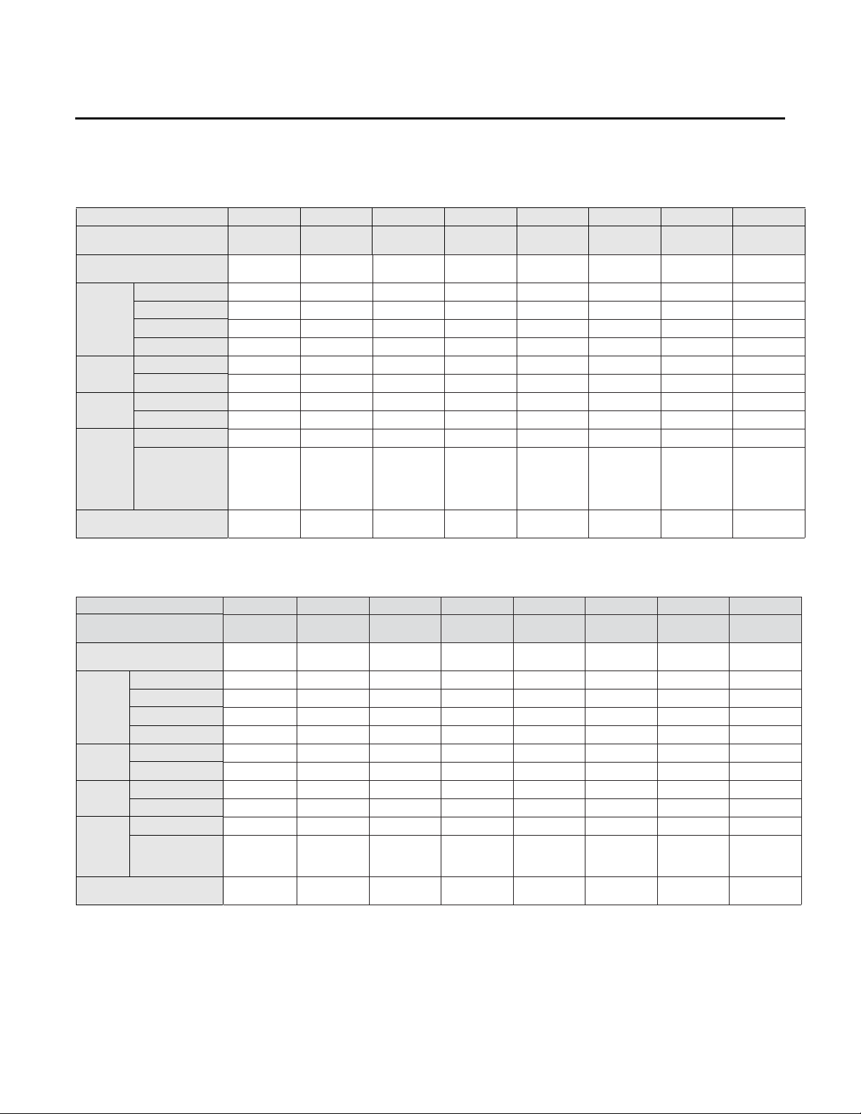
Unit Dimensions and Weight
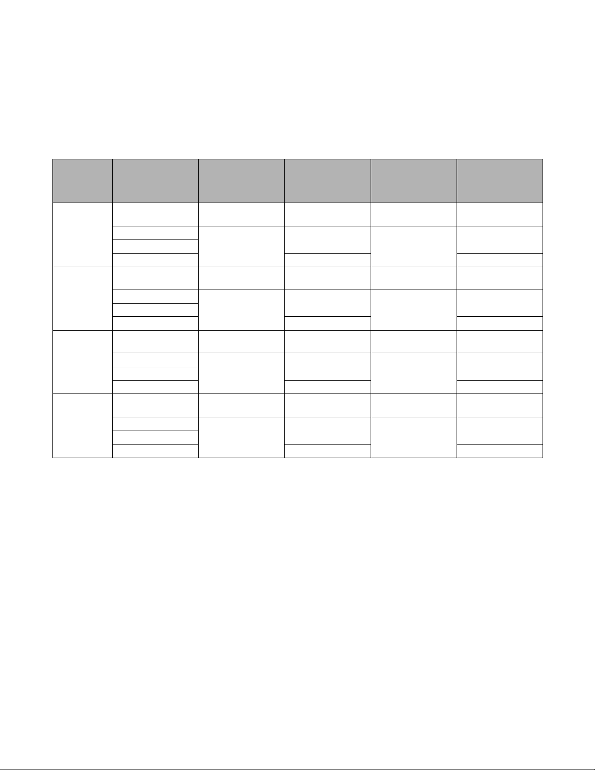
Table 1. Unit dimensions and weight
Dimensions
(WxHxD)
in. (mm)
34.6x66.7x30.1
(880x1695x765)
51.0x66.7x30.1
(1295x1695x765)
34.6x66.7x30.1
(880x1695x765)
51.0x66.7x30.1
(1295x1695x765)
34.6x66.7x30.1
(880x1695x765)
51.0x66.7x30.1
(1295x1695x765)
34.6x66.7x30.1
(880x1695x765)
51.0x66.7x30.1
(1295x1695x765)
Unit type
Heat Pump
(203–230 V)
Heat Recovery
(203–230 V)
Heat Pump
(460 V)
Heat Recovery
(460 V)
Unit model
number
4TVH0072B300NB
4TVH0096B300NB
4TVH0120B300NB
4TVH0144B300NB 657.0 (298) 698.9 (317)
4TVR0072B300NB
4TVR0096B300NB
4TVR0120B300NB
4TVR0144B300NB 672.4 (305) 714.3 (324)
4TVH0072B400NB
4TVH0096B400NB
4TVH0120B400NB
4TVH0144B400NB 672.4 (305) 714.3 (324)
4TVR0072B400NB
4TVR0096B400NB
4TVR0120B400NB
4TVR0144B400NB 692.3 (314) 734.1 (333)
Weight
lb (kg)
425.5 (193)
623.9 (283)
425.5 (193)
637.1 (289)
436.5 (198)
540.1 (245)
445.3 (202)
553.4 (251)
Shipping
dimensions
(WxHxD)
in. (mm)
37.3x75.3x32.8
(948x1912x832)
53.7X75.3x32.8
(1363x1912x832)
37.3x75.3x32.8
(948x1912x832)
53.7X75.3x32.8
(1363x1912x832)
37.3x75.3x32.8
(948x1912x832)
53.7X75.3x32.8
(1363x1912x832)
37.3x75.3x32.8
(948x1912x832)
53.7X75.3x32.8
(1363x1912x832)
Shipping weight
lb (kg)
460.8 (209)
665.8 (302)
460.8 (209)
679.0 (308)
471.8 (214)
582.0 (264)
480.6 (218)
595.2 (270)
6 VRF-SVN34A-EN
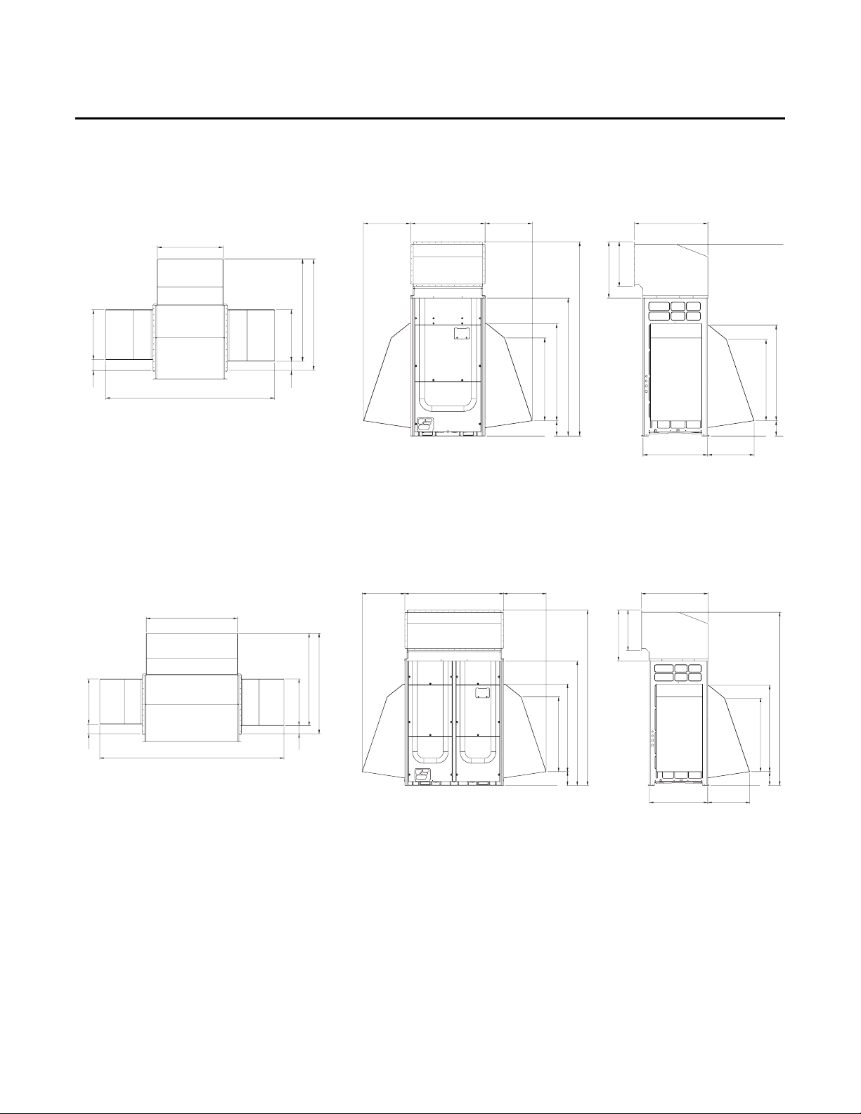
Figure 1. Dimensional drawing: 4TVH072****/4TVR072****
782 (30.79)
560 (22.05) 880 (34.05) 560 (22.05)
871 (34.29)
765 (30.12)
550 (21.65)
2300 (90.55)
668 (26.30)
532 (20.94)
2271 (89 41)
1134 (44.65)
965 (37.99)
180 (7.09)
1632 (64.25)
1150 (45.28)
980 (38.58)
180 (7.09)
2000 (78.74)
127 (5) 593 (23.35)
1318 (51.89)
1210 (47.64)
612 (24.09)
108 (4.25)
Units: mm (inches)
A
A: Optional condenser air discharge duct
B: Optional wind/snow protection duct
A
B
B
B
B
B
B
1197 (47.13)
2415 (95.08)
560 (22.05) 560 (22.05)1295 (50.98)
593 (23.35)127 (5)
1318 (51.89)
1210 (47.64)
612 (24.09)
108 (4.25)
2300 (90.55)
1632 (64.25)
1150 (45.28)
980 (38.58)
180 (7.09)
871 (34.29)
765 (30.12)
550 (21.65)
668 (26.30)
532 (20.94)
2271 (89.41)
1134 (44.65)
965 (37.99)
180 (7.09)
Units: mm (inches)
A
A
B
BB
B
B
B
A: Optional condenser air discharge duct
B: Optional wind/snow protection duct
Preparing for Installation
VRF-SVN34A-EN 7
Figure 2. Dimensional drawing: 4TVH096/120/144****/4TVR096/120/144****
Preparing for Installation
4 (100)
S2: 4 (100)
S1: 20 (500)
4 (100)
12 (300)
4 (100)
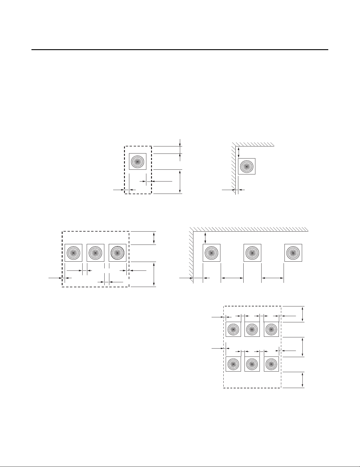
Example 1: Single unit inside pit
Example 2: Single unit inside wall
Front
Front
S1: 20 (500)
16 (400)
16 (400)
4 (100)4 (100)4 (100)4 (100)4 (100)4 (100)
4 (100)
S2: 12 (300)
8 (200)
12 (300)
4 (100)
Notes:
Units: inches (mm)
S1 = Front service clearance
S2 = Back service clearance
See Figure 4, p. 9 for details.
You may install multiple outdoor units with a minimum 1 in.
(20 mm) of space between them, but reduced capacity may
occur depending on the installation environment.
Clearance requirements are waived for any unit sides that have
wind/snow protection ducts installed on them, due to the
wind/snow protection duct size, which exceeds clearance
requirements.
Front
Example 3: Multiple units inside pit
Example 4: Multiple units inside wall
Example 5: Multiple units inside pit
Front
Front
Front
Service Clearances
Install units as shown in the illustrations below, observing ventilation and service requirements.
Space requirements are based on cooling mode operation and an outdoor temperature of 95°F
(35°C). More space is required if the outdoor temperature is higher than 95°F (35°C) or if the area
is easily heated by solar radiation.
Figure 3. Minimum service clearances for single and multiple units
8 VRF-SVN34A-EN
4 (100)
4 (100)
4 (100)
4 (100)
4 (100)
4 (100)
20 (500)
24 (600)
20 (500)
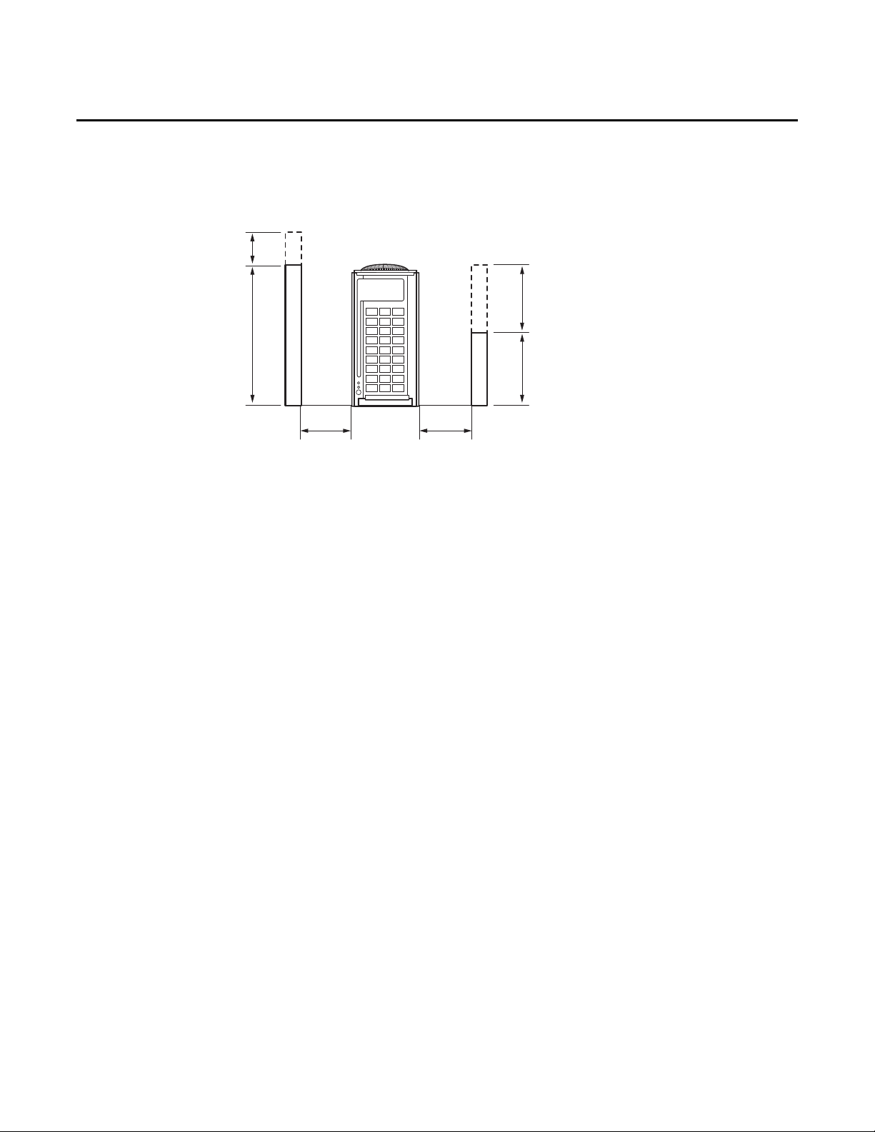
Figure 4. Dimension limits for pit
Front side
Front wall height recommendation: 60 in. (1500 mm) maximum.
Back wall height recommendation: 20 in. (500 mm) maximum.
Side wall height is unlimited.
If a wall exceeds the recommended height, an additional clearance of half of the exceeded height should be added
to the service clearance. (Clearances are given in Figure 3, p. 8).
S1 = Front service clearance
S2 = Back service clearance
h1 = Wall height in excess of 60 in. (1500 mm)
h2 = Wall height in excess of 20 in. (500 mm)
S1+h1/2
S2+h1/2
60 (1500)
h1
20 (500)
h2
Note: This figure refers to Figure 3, examples 1, 3, 5.
Preparing for Installation
Outdoor Unit Combinations
Use the following table to determine the size and number of outdoor units needed to achieve the
capacity requirements.
Follow these guidelines:
• Make sure to use indoor units that are compatible with the outdoor unit.
VRF-SVN34A-EN 9
• The minimum capacity of an indoor unit is 7.5 MBH (7500 Btu/h).
• Indoor units can be connected within the ranges indicated in Ta b le 2 and Ta bl e 3.
• If the total capacity of the connected indoor units exceeds the indicated maximum capacity, the
cooling and heating capacity of the indoor unit may decrease.
• You can connect a maximum of 64 indoor units to the outdoor unit. The maximum quantity of
connectable indoor units is 64 because the outdoor unit supports a maximum of 64
communication addresses.
• If you choose to select outdoor unit combination other than the ones in Ta bl e 2 or Ta bl e 3, the
total capacity of connected indoor units is allowed to be 50%–130% of the outdoor unit capacity:
[0.5 x total outdoor unit capacity
total connected indoor unit capacity 1.3 × total outdoor unit
capacity].
Preparing for Installation
Table 2. Outdoor unit combinations: 6–20 ton capacity
Capacity
Outdoor unit
number
Total number
outdoor
Combined
outdoor
unit
Nominal
Capacity
Rated
Capacity
Tot al
capacity
of
connected
indoor
units
(cooling)
Maximum number
connectable
combination
of
units
4TV*0072*****
4TV*0096*****
4TV*0120*****
4TV*0144*****
Cooling (Btu/h)
Heating (Btu/h)
Cooling (Btu/h)
Heating (Btu/h)
Minimum (Btu/h)
Maximum (Btu/h)
indoor units
individual
of
6 ton 8 ton 10 ton 12 ton 14 ton 16 ton 18 ton 20 ton
4TV*0072***** 4TV*0096***** 4TV*0120***** 4TV*0144***** 4TV*0168***** 4TV*0192***** 4TV*0216***** 4TV*0240*****
11112222
1111
11
112
72000 96000 120000 144000 168000 192000 216000 240000
81000 108000 135000 162000 189000 216000 243000 270000
69000 92000 114000 138000 161000 183000 207000 228000
77000 103000 129000 154000 180000 206000 231000 258000
36000 48000 60000 72000 84000 96000 108000 120000
93600 124800 156000 187200 218400 249600 280800 312000
12 16 20 25 29 33 37 41
Table 3. Outdoor unit combinations: 22–36 ton capacity
Capacity
Model name for
Combination
Total number
outdoor
Combine
d outdoor
unit
Nominal
capacity
Rated
capacity
Tot al
capacity
of
indoor
units
(cooling)
Maximum number
connectable
of
units
4TV*0072
4TV*0096*****
4TV*0120*****
4TV*0144*****
Cooling (Btu/h)
Heating (Btu/h)
Cooling (Btu/h)
Heating (Btu/h)
Minimum (Btu/h)
Maximum (Btu/h)
indoor units
individual
*****
of
22 ton 24 ton 26 ton 28 ton 30 ton 32 ton 34 ton 36 ton
4TV*0264***** 4TV*0288***** 4TV*0312***** 4TV*0336***** 4TV*0360**** 4TV*0384***** 4TV*0408**** 4TV*0432*****
22333333
111
1
1121
12112123
264000 288000 312000 336000 360000 384000 408000 432000
297000 324000 351000 378000 405000 432000 459000 486000
252000 276000 299000 321000 345000 366000 390000 414000
283000 308000 334000 360000 385000 412000 437000 462000
132000 144000 156000 168000 180000 192000 204000 216000
343200 374400 405600 436800 468000 499200 530400 561600
45 49 54 58 62 64 64 64
11
10 VRF-SVN34A-EN
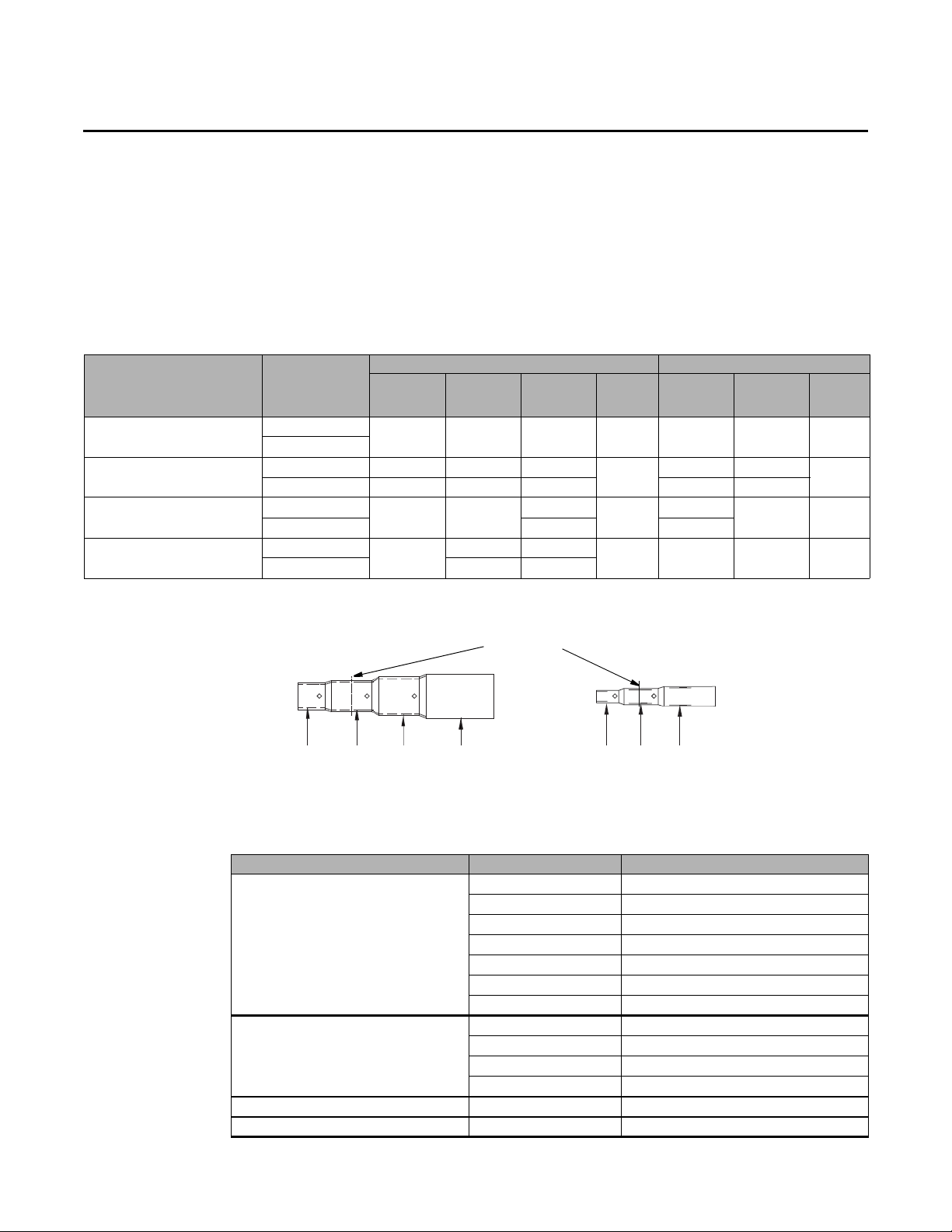
Accessories
Cutting line
ID3/4 in.
ID7/8 in.
ID 1 in.
ID 1-1/8 in. ID3/8 in.
ID 5/8in.
ID 1/2 in.
Accessories that ship with the unit are:
• Instruction manual
• Brand label and instruction sheet
• Pipe installation sockets (see Ta bl e 4 and Figure 5).
Table 4. Pipe installation socket size chart
Model number Connection type
4TV*0072***** (6 ton)
4TV*0096***** (8 ton)
4TV*0120***** (10 ton)
4TV*0144***** (12 ton)
(a) Cut socket as needed for 8, 10, and 12 ton units.
(a)
Unit connection
Field connection
Unit connection 1-1/8 in. 1/2 in. 7/8 in.
Field connection 7/8 in. 3/8 in. 3/4 in. 7/8 in. 3/8 in.
Unit connection
(a)
Field connection 3/4 in. 1-1/8 in.
Unit connection
(a)
Field connection 1/2 in. 7/8 in.
Preparing for Installation
Heat recovery Heat pump
High-
pressure
Gas Liquid
3/4 in. 3/8 in. 5/8 in. No 3/4 in. 3/8 in. No
1-1/8 in. 1/2 in.
1-1/8 in.
5/8 in. 1-1/8 in.
gas
7/8 in.
Socket
needed
Yes
Yes
Yes 1-1/8 in. 1/2 in. No
Gas Liquid
1 in. 1/2 in.
1 in.
1/2 in. Yes
Socket
needed
Yes
Figure 5. Pipe installation sockets
Ta b le 5 shows optional accessories for outdoor units.
Table 5. Optional accessories
Accessory Model number Specification
4YDK1509B0051A 51 MBH and below
4YDK2512B0138A Over 51–136 MBH
4YDK2812B0160A Over 136–154 MBH
Y-j oi n t
Y-j oi n t
(high-pressure gas for heat recovery units)
Y-joint for outdoor unit 4TDK3819B0000A 456 MBH and below
High-pressure Y-joint for outdoor unit 4TDK3100B0000A 456 MBH and below
4YDK2815B0240A Over 154–240 MBH
4YDK3419B0336A Over 240–336 MBH
4YDK4119B0468A Over 336–461 MBH
4YDK4422B0999A Over 461 MBH
4YDK1500B0080A 76 MBH and below
4YDK2500B0240A Over 76–240 MBH
4YDK3100B0468A Over 240–461 MBH
4YDK3800B0999A Over 461 MBH
VRF-SVN34A-EN 11
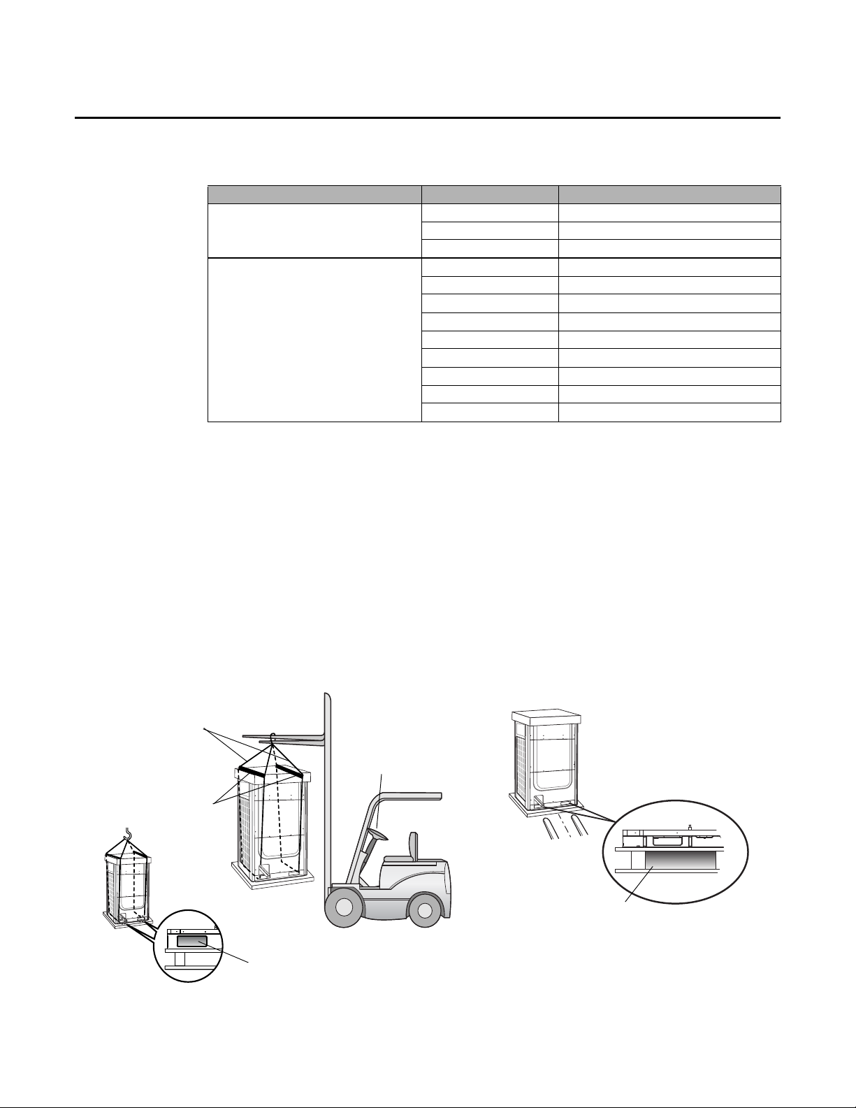
Preparing for Installation
Moving with a crane Moving with a forklift
Holes for wire cable
to pass through
Holes for inserting forklift
Wire cables
Holes for wire cable
to pass through
Spreader bars
Table 5. Optional accessories (continued)
Accessory Model number Specification
Distribution header
Electronic expansion valve (EEV) kit
(a) Required for indoor units that do not have internal EEVs. Refer to the EEV kit installation guide (VRF-SVN43) for detailed
information.
Moving the Outdoor Unit
Follow these guidelines when moving the outdoor unit:
• Before moving the outdoor unit, determine a path that can support its weight.
• Do not lay the unit on its side and do tip it more than 30 degrees.
• Take care to avoid injury while moving the unit; the surface of the heat exchanger is sharp.
– If moving the unit with a crane, fasten the wire rope as shown in the figure below. To protect
damage or scratches to the unit, use a spreader bar.
– If moving the unit with a forklift, carefully insert forks into the forklift holes at the bottom of
the outdoor unit. Be careful with to avoid damaging the unit with the forklift.
(a)
4HJK2512B0159A 154 MBH and below (for 4 rooms)
4HJK3115B0241A 240 MBH and below (for 8 rooms)
4HJK3819B0998A Over 240 MBH (for 8 rooms)
4EEVEVA24SA000 Below 12 MBH (for 1 indoor unit)
4EEVEVA32SA000 Over 18 MBH (for 1 indoor unit
4EEVXDA24K132A
4EEVXDA24K200A
4EEVXDA32K200A 17-31 MBH (for 2 indoor units)
4EEVXDA24K232A
4EEVXDA24K300A
4EEVXDA32K224A 17-31 MBH (
4EEVXDA32K300A 17-31 MBH (
7‐15.5MBH(for 2 indoor units )
7‐15.5MBH(for 2 indoor units)
7‐15.5MBH(for 3 indoor units)
7‐15.5MBH(for 3 indoor units)
for3indoorunits)
for3indoorunits)
12 VRF-SVN34A-EN
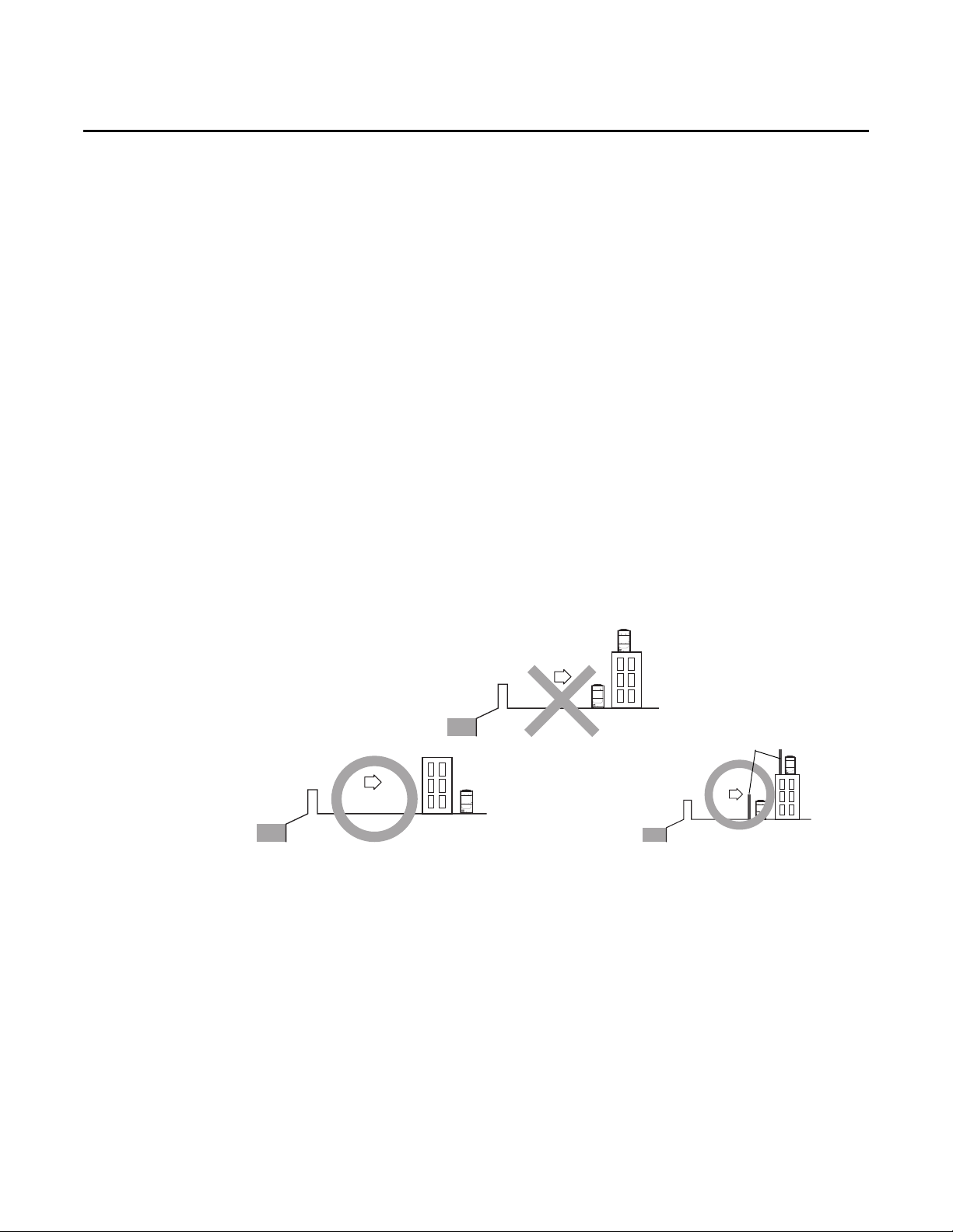
Location Considerations
Sea Sea
Sea
Sea breeze
Sea breeze
Protection wall
Sea breeze
ODU
ODU
ODU
ODU
ODU
Choose an installation location based on the following considerations.
• Install the outdoor unit:
– On a supporting structure that can bear the weight of the outdoor unit. The supporting
structure can be a base on the ground, on a waterproof roof, or in a pit.
– With sufficient clearances around the unit for service and repairs.
– On a flat surface that does not collect water
– In a well ventilated location
– Away from strong wind
– Away from direct exposure to rain or snow
– Where there is no risk of flammable gas leakage
– Where there is no exposure to salt, machine oil, sulfide gas, or corrosive environmental
conditions
– Away from sea breeze
Note: For seacoast applications, block the unit from direct exposure to sea breeze by installing
the outdoor unit (ODU) behind a structure (such as a building) or a protective wall that
is 1.5 times higher than the unit, leaving 28 in. (700 mm) of space between the wall and
unit for air circulation. Consult an installation expert about taking anti-corrosion
measures, such as removing salinity on the heat exchanger and applying a rust inhibitor
more frequently than once a year.
Preparing for Installation
– At least 9.84 ft (3 m) away from equipment that generates electromagnetic waves.
– Away from interfering sources, such as radio, computer, and stereo equipment.
– Far enough away from people living and working nearby so that hot discharge air or noise
do not disturb them.
– Away from inflammable materials.
• Ensure that condensate water generated by the outdoor unit can drain smoothly away from the
unit.
• Install the power and communication cables in a separately installed enclosure.
• If installing on a high place such as a roof, a fence or guard rail should be installed around it
to safeguard from falls.
• If there is a potential for accumulated snow to block the air inlet or heat exchanger, install the
unit on a base higher than the highest possible snow accumulation.
VRF-SVN34A-EN 13

Preparing for Installation
• R-410A refrigerant is a safe, nontoxic and nonflammable refrigerant. However, if there is a
concern about a dangerous level of refrigerant concentration in the case of refrigerant leakage,
add extra ventilation.
• Avoid installing the outdoor unit where corrosive gases, such as sulfur oxides, ammonia, and
sulfurous gas, are produced. If unavoidable, consult with an installation specialist about using
a corrosion-proof or anti-rust additive to protect the unit coils.
• Apply corrosion protection and any other protective coatings to the unit as appropriate to the
environment.
14 VRF-SVN34A-EN
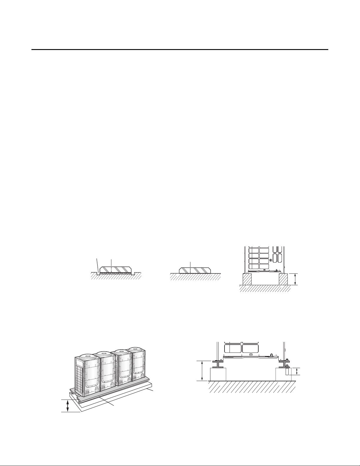
Unit Installation
Ground installation
Base installation: Surface of
base must be horizontally level
Raised base
8 in. (200 mm) min.
8 in. (200 mm)
Drain pit
Base
H-beam or vibration-isolation frame
8 in. (200 mm)
minimum
8 in. (200 mm)
minimum
2 in. (50 mm)
minimum
H-beam frame on concrete supports
Follow these guidelines for installing the outdoor unit.
Important: The manufacturer is not responsible for damage incurred for installations that have
not followed these guidelines.
The outdoor unit must be installed:
– On a horizontally level surface.
– On a surface that is strong enough to support the unit and to minimize noise.
Base Recommendations
A supporting base for the outdoor unit:
• Is typically made of concrete.
• Should typically be 1.5 times larger than the bottom of the outdoor unit. However, for
installations that are subject to snow accumulation, the base should be no larger than the
bottom of the unit.
• Should be 8 in. (200 mm) or higher to protect the outdoor unit from rain water or other
conditions that may cause damage to the unit.
Note: The height of the base or, if the unit is installed on a frame (see “Minimizing Vibration”
p. 15), the height of the base plus the frame should be greater than the highest expected
snowfall.
• If necessary, has wire mesh or steel bars added to the concrete to prevent damages or cracks.
Unit Installation
Minimizing Vibration
To minimize outdoor unit vibrations, use a vibration-minimizing structure such as an H-beam
frame, a vibration-isolation frame, or an isolation pad (thickness > 1 in. [20 mm]). The load-bearing
force of the structure must be 787 lbf (3.5 kN).
VRF-SVN34A-EN 15
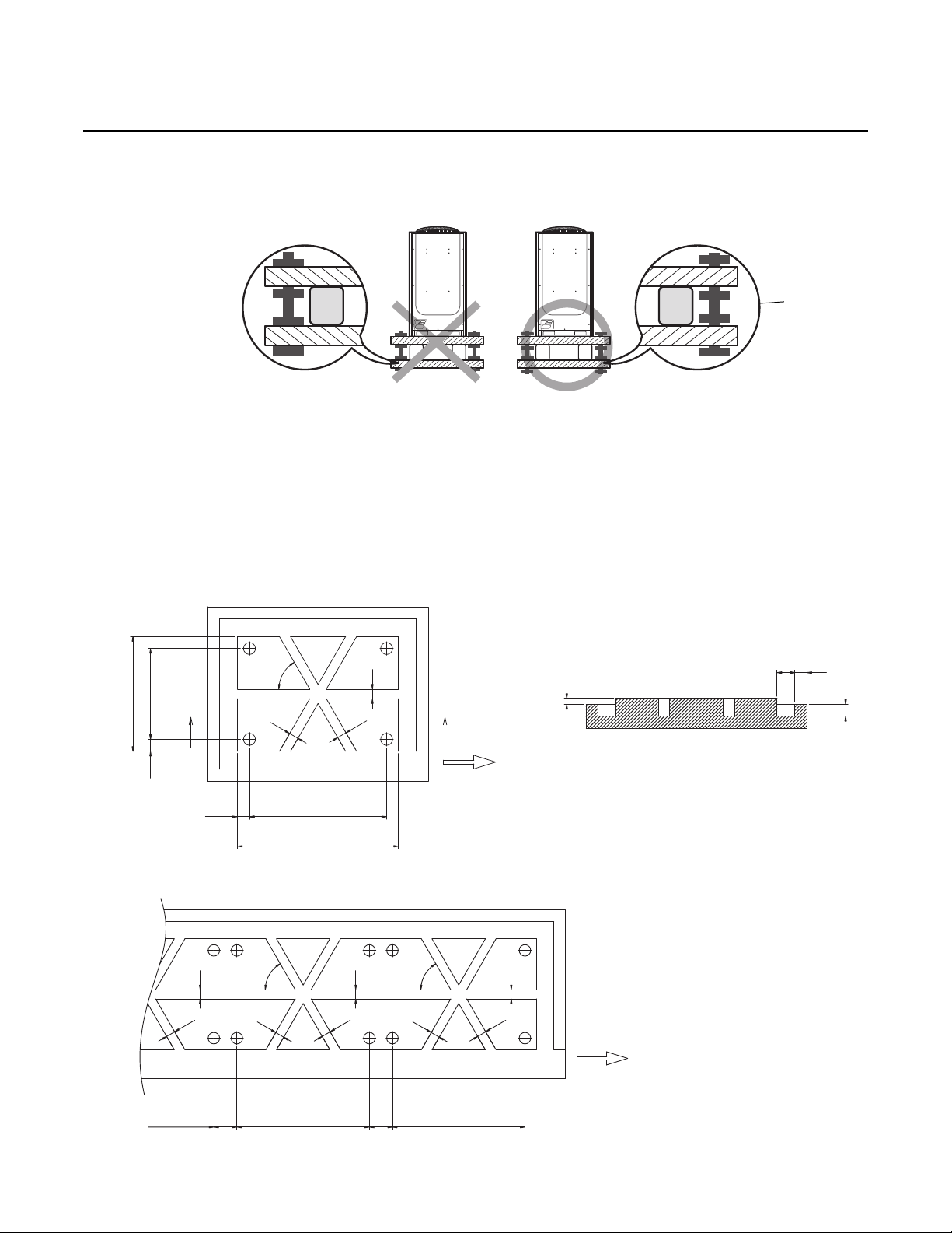
Unit Installation
Vibration-isolation frame
Ensure that
bolts are loose.
37.80 (960)
39.92 (760)
3.94 (100)
3.94 (100)
X
B
A
X’
3.15 (80)
3.15 (80)
3.15 (80)
60°
1.97 (50)
5.91 (150)
3.94 (100)
3.94
(100)
Notes:
• Units: inch (mm)
• Refer to Tab l e 7 for A and B.
Drainage direction
(slope: 1/50)
X - X’ section
3.15 (80)
3.15 (80)
3.15 (80)
3.15 (80)
3.15 (80)
3.15 (80)
3.15 (80)
3.15 (80)
60°
60°
7.87
(200)
7.87
(200)
BB
Notes:
• Units: inch (mm)
•Refer to Ta b l e 7 for A and B.
Drainage direction
(slope: 1/50)
After installing a vibration-isolation frame, loosen the bolts so that the isolators are capable of
absorbing vibrations (refer to the figure below).
Water Management Recommendations
If the outdoor unit base is on ground level, construct a drainage pit around it to prevent the drain
water from collecting near the unit.
• Use wire mesh or steel bar for constructing the drainage pit.
• Construct the pit with a slope of 1:50.
Figure 6. Water management for single-unit installation
Figure 7. Water management for multiple-unit installation
16 VRF-SVN34A-EN
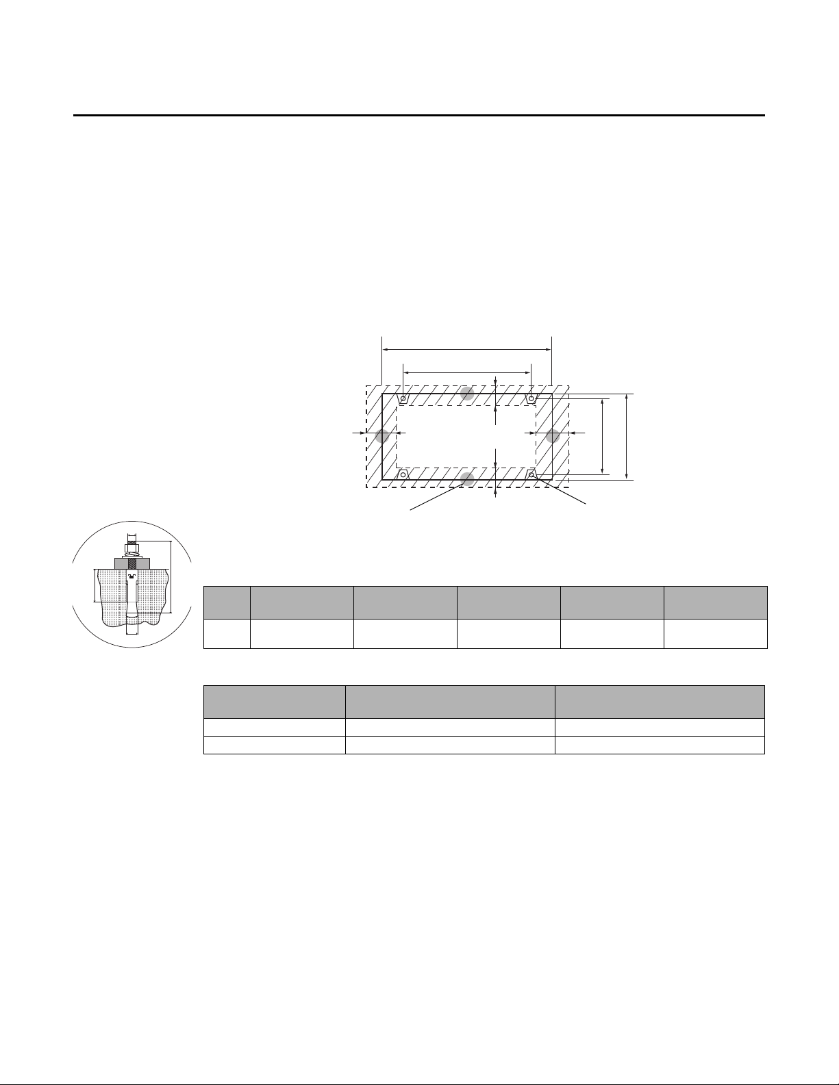
Securing the Outdoor Unit
A
B
Isolation mounts:
4 holes, 0.71 (18)
Outdoor unit:
4 holes, 0.47 (12)
2.13 (54)
30.0 (761)
31.6 (803)
Notes:
•Units: inch (mm)
•Refer to Ta b l e 7 for A and B.
•
Refer to the blueprints in the
technical data book for hole
specifications for mounting.
a
b
c
m
Secure the outdoor unit firmly to the base with anchor bolts (see Figure 8 and Ta b le 6).
• Use zinc-plated or stainless steel nuts and bolts.
• It must be able to withstand the wind speed of 67 mph (30 m/s).
• Use a rubber washer between the bolt and the outdoor unit to prevent bimetallic corrosion.
• If you cannot attach the outdoor unit to the base, secure it from the side or to an additional
structure.
Figure 8. Bolt hole sizes and locations for mounting the outdoor unit
Unit Installation
Table 6. Anchor specification
Size
(m)
10 mm 1/2 in. (14 mm) 3 in. (75 mm) 1-1/2 in. (40 mm) 2 in. (50 mm)
Drill bit
diameter (a)
Anchor length
(b)
Sleeve length
(c)
Insertion depth
Fastening
265.5 in·lbf
Table 7. Unit and bolt dimensions
4TVH072*****
Dimensions
Unit width (A) 37.01 in. (940 mm) 53.15 in. (1350 mm)
Distance between bolts (B) 29.13 in. (740 mm) 45.28 in. (1150 mm)
4TVR072*****
4TVH096/120/144*****
4TVR096/120/144*****
torque
(30 N·m)
VRF-SVN34A-EN 17

Unit Installation
Examples of condenser air discharge ducts
Discharge air
Discharge air
Suction air
Grille/louvers
Upper floor
Balcony
Mechanical room
Condenser Air Discharge Duct (optional)
CAUTION
Sharp Edges!
Working with galvanized sheet metal involves working with sharp edges. To avoid being cut,
technicians MUST put on all necessary Personal Protective Equipment (PPE), including gloves
and arm guards.
If you remove the fan guard to install the discharge duct, make sure to install a safety net on
the duct outlet to prevent foreign substances from entering the unit and to prevent the risk of
personal injury from sharp fan blades.
A discharge duct can be installed on the outdoor unit to prevent foreign substances from entering
the unit.
The static pressure of the discharge duct should be within the standard specification of 0.02 inches
of water (78.45 Pa) when installing the duct.
If it is difficult to provide a minimum of 6.56 ft (2 m) of space between the air outlet and nearby
obstacles, direct the discharge air horizontally from the fan.
18 VRF-SVN34A-EN
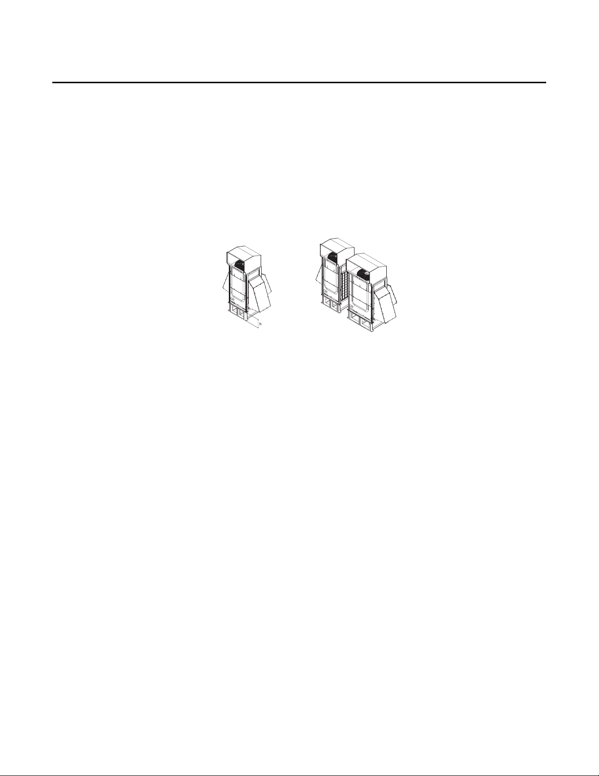
Wind/Snow Prevention Duct Installation (optional)
A wind/snow prevention should be installed:
• In snowy regions, to prevent snow from accumulating on the outdoor unit and the risk of
accumulated frost, which may interfere with normal heating operation.
• In windy regions, such as near a sea shore, to protect the unit from humid air.
Install the duct so that:
• The discharge air and prevailing wind are not going the same direction.
• The discharge air is not directed to the enclosed area.
• Height (h) of the frame or base should be higher than the heaviest expected snowfall.
Unit Installation
VRF-SVN34A-EN 19

Refrigerant Piping
A(2)
B
C
A(3)
A(1)
D
E
F
10 ton10 ton
8 ton
8 ton
Outdoor
unit
capacity
(ton)
Pipe A
Pipe size (OD)
Liquid
in. (mm)
Gas
in. (mm)
10 A(1) 1/2 (12.70) 1-1/8 (28.58)
18 A(2) 5/8 (15.88) 1-1/8 (28.58)
26 A(3) 3/4 (19.05) 1-3/8 (34.92)
Key
A(1): Select based on individual outdoor unit capacity (Table 8, p. 21).
A(2): Select based on the sum of outdoor unit capacity behind the first outdoor unit multi-connection (Tab l e 8 , p. 2 1 ).
A(3): Select based on the sum of outdoor unit capacity before the first branch joint (Table 8, p. 21).
B: Pipes between branch joints (Tab l e 9 , p . 2 1)
C: Outdoor joints between outdoor units (Table 14, p. 24)
D: First branch joint (Table 15, p. 24))
E: Branch joints to indoor units (Table 16, p. 25))
F: Pipe size between branch joints and indoor units (Table 13, p. 24)
Refrigerant Piping
This section contains information on selecting, storing, and connecting refrigerant piping.
Selecting Refrigerant Piping
Refrigerant piping diameter, thickness, and temper is selected according to length, as specified in
this section.
Notes:
• Use insulated, unwelded, degreased, and deoxidized copper pipe (Cu-DHP type according
to ISO 1337 or UNI EN 12735-1) suitable for an operating pressure of at least 609.15 psi
(4200 kPa) and a burst pressure of at least 3002.28 psi (20,700 kPa). Copper pipe for hydrosanitary applications is unsuitable.
• If there is a risk of decreased performance caused by pipe length, use piping that is one
size larger than that specified in this section.
Heat Pump Applications
The example in Figure 9 shows a 26-ton capacity heat pump system with pipe diameters specified.
Figure 9. Heat pump system example
20 VRF-SVN34A-EN
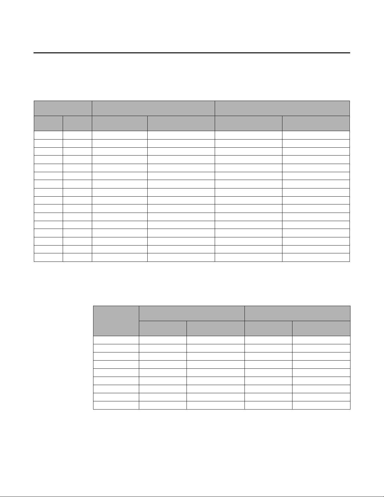
Use Tab le 8 to determine the size of the main pipes based on pipe length. (Refer to A in Figure 13,
p. 32)
Table 8. Outdoor unit main pipe size based on pipe length (A)
Refrigerant Piping
Outdoor unit
capacity
when pipe length is 295.3 ft (90 m)
Ton MBH
6 72 3/8 (9.52) 3/4 (19.05) 1/2 (12.70) 7/8 (22.22)
8 96 3/8 (9.52) 7/8 (22.22) 1/2 (12.70) 1 (25.4)
10 120 1/2 (12.70) 1-1/8 (28.58) 5/8 (15.88) 1-1/8 (28.58)
12 144 1/2 (12.70) 1-1/8 (28.58) 5/8 (15.88) 1-1/4 (31.75)
14 168 5/8 (15.88) 1-1/8 (28.58) 3/4 (19.05) 1-1/4 (31.75)
16 192 5/8 (15.88) 1-1/8 (28.58) 3/4 (19.05) 1-1/4 (31.75)
18 216 5/8 (15.88) 1-1/8 (28.58) 3/4 (19.05) 1-1/4 (31.75)
20 240 5/8 (15.88) 1-1/8 (28.58) 3/4 (19.05) 1-1/4 (31.75)
22 264 3/4 (19.05) 1-3/8 (34.92) 7/8 (22.22) 1-1/2 (38.1)
24 288 3/4 (19.05) 1-3/8 (34.92) 7/8 (22.22) 1-1/2 (38.1)
26 312 3/4 (19.05) 1-3/8 (34.92) 7/8 (22.22) 1-1/2 (38.1)
28 336 3/4 (19.05) 1-3/8 (34.92) 7/8 (22.22) 1-1/2 (28.1)
30 360 3/4 (19.05) 1-5/8 (41.28) 7/8 (22.22) 1-5/8 (41.28)
32 384 3/4 (19.05) 1 5/8 (41.28) 7/8 (22.22) 1-5/8 (41.28)
34 408 3/4 (19.05) 1 5/8 (41.28) 7/8 (22.22) 1-5/8 (41.28)
36 432 3/4 (19.05) 1 5/8 (41.28) 7/8 (22.22) 1-5/8 (41.28)
(a) If 1 (25.4) pipe is not available on site, use 1 1/8 (28.58) pipe.
(b) If 1-1/4(31.75) pipe is not available on site, use 1 3/8 (34.92) pipe.
(c) If 1-1/2 (38.1) pipe is not available on site, use 1 5/8 (41.28) pipe.
Main pipe size (OD)
Liquid
in. (mm)
Gas
in. (mm)
when pipe length > 295.3 ft (90 m)
Main pipe size (OD)
Liquid
in. (mm)
in. (mm)
Gas
(a)
(b)
(b)
(b)
(b)
(b)
(c)
(c)
(c)
(c)
Use Ta b le 9 to determine the size of pipes between branch joints. (Refer to B in Figure 13, p. 32.)
Table 9. Pipe size between branch joints (B)
Branch pipe size (OD) when pipe is
Indoor unit
total capacity
(MBH)
Less than 51 3/8 (9.52) 5/8 (15.88) 1/2 (12.70) 3/4 (19.05)
51-75.9 3/8 (9.52) 3/4 (19.05) 1/2 (12.70) 7/8 (22.22)
76-95.9 3/8 (9.52) 7/8 (22.22) 1/2 (12.70) 1 (25.4)
96-135.9 1/2 (12.70) 1-1/8 (28.58) 5/8 (15.88) 1-1/8 (28.58)
136-153.9 1/2 (12.70) 1-1/8 (28.58) 5/8 (15.88) 1-1/4 (31.75)
154-239.9 5/8 (15.88) 1-1/8 (28.58) 3/4 (19.05) 1-1/4 (31.75)
240-335.9 3/4 (19.05) 1-3/8 (34.92) 7/8 (22.22) 1-1/2 (38.1)
336–460.9 3/4 (19.05) 1-5/8 (41.28) 7/8 (22.22) 1-5/8 (41.28)
461–577 3/4 (19.05) 1 5/8 (41.28) 7/8 (22.22) 2-1/8 (53.98)
(a) If 1 (25.4) pipe is not available on site, use 1-1/8 (28.58) pipe.
(b) If 1-1/4 (31.75) pipe is not available on site, use 1-3/8 (34.92) pipe.
(c) If 1-1/2 (38.1) pipe is not available on site, use 1-5/8 (41.28) pipe.
147.6 ft (45 m)
Liquid
in. (mm)
Gas
in. (mm)
VRF-SVN34A-EN 21
Branch pipe size (OD) when pipe is
147.6–295.3 ft (45–90 m)
Liquid
in. (mm)
Gas
in. (mm)
(a)
(b)
(b)
(c)
Loading...