


4-267-263-72(1)
Digital Surround
Headphone System
Operating Instructions ______US
Mode d’emploi ____________FR
Manual de instrucciones ____ES
MDR-DS6500
© 2011 Sony Corporation

WARNING
To reduce the risk of fire or electric shock, do not expose this apparatus to rain or moisture.
For customers in the USA
Owner’s Record
The model number is located at the bottom of the processor and both side of the headband.
The serial number is located at the bottom of the processor and right inner side of the headband.
Record these numbers in the spaces provided below. Refer to them whenever you call upon your Sony dealer regarding this product.
Model No. MDR-DS6500
Processor DP-RF6500 Headphones MDR-RF6500
Serial No.
Processor __________________________
Headphones ________________________
The following FCC statement applies only to the version of this model manufactured for sale in the USA. Other versions may not comply with FCC technical regulations
NOTE
This equipment must not be co-located or operated in conjunction with any other antenna or transmitter.
NOTE
This equipment has been tested and found to comply with the limits for a Class B digital device, pursuant to Part 15 of the FCC Rules. These limits are designed to provide reasonable protection against harmful interference in a residential installation. This equipment generates, uses and can radiate radio frequency energy and, if not installed and used in accordance with the instructions, may cause harmful interference to radio communications. However, there
is no guarantee that interference will not occur in a particular installation. If this equipment does cause harmful interference to radio or television reception, which can be determined by turning the equipment off and on, the user is encouraged to try to
correct the interference by one or more of the following measures:
−Reorient or relocate the receiving antenna.
−Increase the separation between the equipment and receiver.
−Connect the equipment into an outlet on a circuit different from that to which the receiver is connected.
−Consult the dealer or an experienced radio/ TV technician for help.
For the state of California, USA only Perchlorate Material - special handling may apply, See www.dtsc.ca.gov/hazardouswaste/ perchlorate
Perchlorate material: Lithium battery contains perchlorate
CAUTION
You are cautioned that any changes or modifications not expressly approved in this manual could void your authority to operate this equipment.
2US

For customers in Canada
Operation is subject to the following two conditions: (1) this device may not cause interference, and (2) this device must accept any interference, including interference that may cause undesired operation of the device.
This Class B digital apparatus complies with Canadian ICES-003.
The following FCC/IC statement applies only to the version of this model manufactured for sale in the USA and Canada. Other versions may not comply with FCC/IC technical regulations.
This headphones comply with FCC/IC radiation exposure limits set forth for an uncontrolled environment and meets the FCC radio frequency (RF) Exposure
Guidelines in Supplement C to OET65 and RSS-102 of the IC radio frequency (RF) Exposure rules. This equipment has very low levels of RF energy that are deemed to comply without testing of specific absorption ratio (SAR).
This processor complies with FCC/IC radiation exposure limits set forth for an uncontrolled environment and meets the FCC radio frequency (RF) Exposure
Guidelines in Supplement C to OET65 and RSS-102 of the IC radio frequency (RF) Exposure rules.
This processor has very low levels of RF energy that it deemed to comply without maximum permissive exposure evaluation (MPE). But it is desirable that it should be installed and operated keeping the radiator at least 20 cm or more away from person’s body (excluding extremities: hands, wrists, feet and ankles).
FOR UNITED STATES CUSTOMERS. NOT APPLICABLE IN CANADA, INCLUDING IN THE PROVINCE OF QUEBEC.
POUR LES CONSOMMATEURS AUX ÉTATS-UNIS. NON APPLICABLE AU CANADA, Y COMPRIS LA PROVINCE DE QUÉBEC.
This device complies with Part 15 of the FCC Rules.
Operation is subject to the following two conditions:
(1)this device may not cause harmful interference, and
(2)this device must accept any interference received, including interference that may cause undesired operation.
US
3US

Table Of Contents |
|
Main Features ................................... |
5 |
Checking the Components and |
|
Accessories..................................... |
6 |
Location and Function of Parts........ |
7 |
Processor Part Descriptions....................... |
7 |
Headphones Part Descriptions.................. |
9 |
Charging the Headphones............ |
10 |
Checking the remaining battery |
|
power ...................................................... |
12 |
Connecting the Headphone |
|
System......................................... |
13 |
Connecting the processor to digital |
|
components............................................ |
13 |
Connecting the processor to analog |
|
components............................................ |
14 |
Listening to a Connected |
|
Component ................................. |
16 |
Replacing the Ear Pads.................. |
23 |
Troubleshooting ............................ |
24 |
Precautions .................................... |
28 |
Specifications................................. |
29 |
4US

Main Features
The MDR-DS6500 is a digital surround headphone system that allows you to enjoy the surround sound field of a BD/DVD or other multi-channel source wirelessly.
You can enjoy multi-channel surround sound with headphones by simply connecting the digital surround processor to a BD/DVD device, digital satellite/TV receiver, GAME device or other device with the supplied cable.
7.1ch VPT (Virtualphones Technology)*1 reproduces the three-dimensional surround of multi-channel speakers.
Large size 40 mm driver units for premium movie theater sound quality.
Wireless transmission means you can use these headphones anywhere indoors without worrying about things getting in the way. CD sound quality achieved by uncompressed digital transmission. (Transmission distance: Up to approx. 100 m*2)
Selectable surround mode. (CINEMA/GAME/VOICE (STEREO))
Automatic tuning on headphones for the best reception of signal. The system can switch to a free channel automatically without any sound interruption before the signal is blocked.
Fast recharging function with secure charging mechanism.
Long playback time. (approx. 20 hours)
Wide variety of media formats supported.
(Max. 7.1ch sound field achieved by Dolby Pro Logic IIx support*3. Supported media formats: Dolby Digital, Dolby Digital Surround EX, DTS, DTS-ES Matrix, and DTS-ES Discrete)
*1 “Virtualphones Technology” is a registered trademark of Sony Corporation.
*2 Transmission distance varies depending on condition of use.
*3 The processor of this system incorporates the Dolby Digital decoder, Dolby Pro Logic IIx decoder, and DTS decoder.
The processor of this system is manufactured under license from Dolby Laboratories and Digital Theater Systems, Inc.
Manufactured under license from Dolby Laboratories. Dolby, Pro Logic, and the double-D symbol are trademarks of Dolby Laboratories.
Manufactured under license under U.S. Patent #’s: 5,451,942; 5,956,674; 5,974,380; 5,978,762; 6,487,535 & other U.S. and worldwide patents issued & pending. DTS and the Symbol are registered trademarks & DTS Digital Surround and the DTS logos are trademarks of DTS, Inc. Product includes software. © DTS, Inc. All Rights Reserved.
5US
Preparation
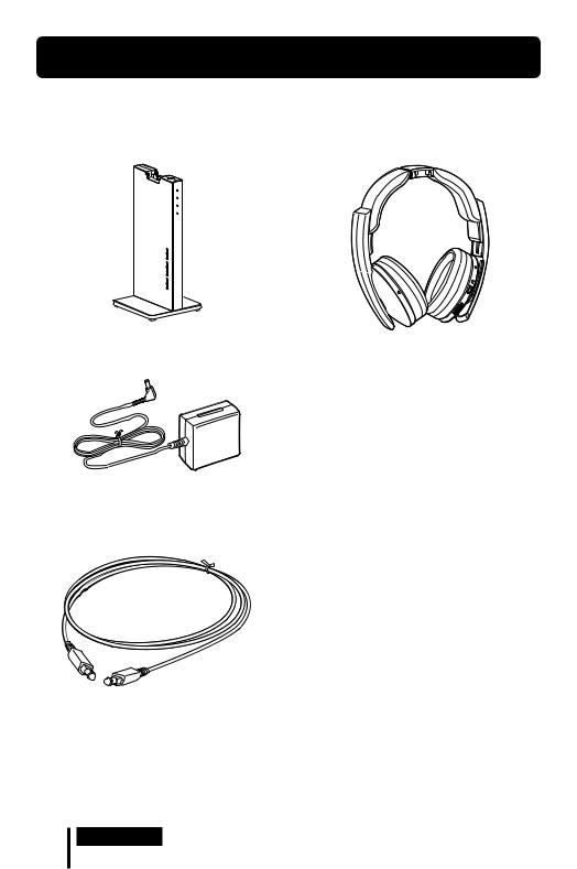
Checking the Components and Accessories
Before setting up the system, check that all of the components are included.
Processor DP-RF6500 (1) |
Wireless stereo headphones MDR-RF6500 (1) |
AC power adaptor (1)
Optical digital connecting cable (rectangular type rectangular type) (1)
6US Preparation

Location and Function of Parts
Processor Part Descriptions
Contact pin
/ (on/standby) button
Power indicator
Lights up in green while emitting RF signals.
Decode Mode indicators
(See page 19 for details.)
COMPRESSION switch
(See page 18 for details.)
EFFECT switch
(See page 17 for details.)
Slide to select the sound field (CINEMA/ GAME/VOICE (STEREO)/OFF).
INPUT switch
(See page 17 for details.)
Slide to select the input source (DIGITAL/ ANALOG).
DC IN 6V jack
Connect the supplied AC power adaptor to this jack. (Be sure to use the supplied AC power adaptor. Using products with a different plug polarity or other characteristics can cause a malfunction.)
ATT (attenuator) switch
Set this switch to “0 dB” if the volume is too low for analog input. Normally, this switch
should be set to “–8 dB.”
(Continued)
Preparation 7US

LINE IN jacks
(See page 14 for details.)
Connect the audio output jacks on an audio or video component (sold separately), such as a video cassette player or TV, stereo system, VCR, etc. to these jacks.
DIGITAL IN jack
(See page 13 for details.)
Connect a BD/DVD device, digital satellite/ TV receiver, or other digital component (sold separately) to this jack.
8US Preparation
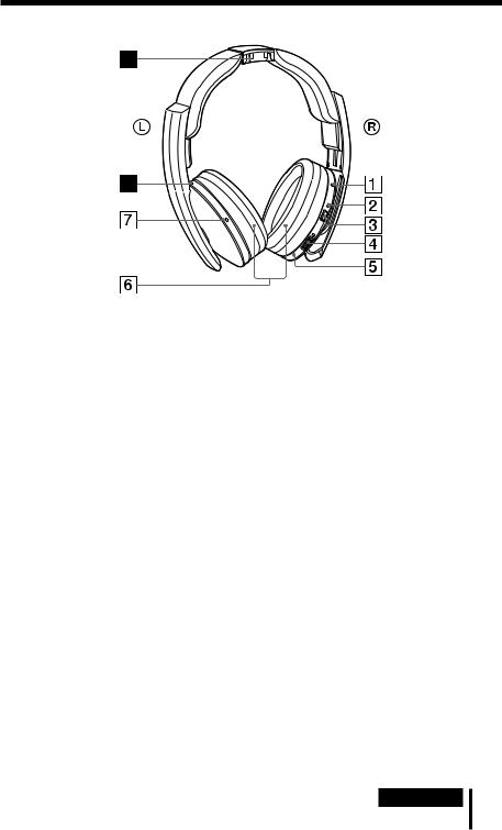
Headphones Part Descriptions
Reset button
Power indicator
The power indicator lights up in green when the power is on.
POWER button
VOL (Volume) control*
Use to adjust the volume.
Right housing
Ear pad
Left housing*
Charging indicator
Lights up in red while charging.
Contact point
*There is a tactile dot on the headphones for easy recognition.
Preparation 9US
Charging the Headphones
The headphones contain a rechargeable Lithium-Ion battery.
Be sure to charge it before using for the first time.
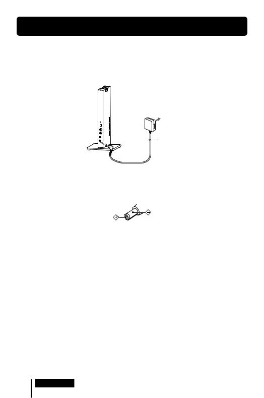
To charge the headphones, place them on the processor.
1 Connect the supplied AC power adaptor to the processor.
Processor |
To an AC outlet |
|
|
|
AC power |
|
adaptor |
|
(supplied) |
To DC IN 6V jack
Notes
Be sure to use the supplied AC power adaptor. Using AC adaptors with different plug polarity or other characteristics can cause product failure.
Unified polarity plug
Be sure to always use the supplied AC power adaptor. Even AC power adaptors having the same voltage and plug polarity can damage this product due to the current capacity or other factors.
Connect the AC power adaptor to an easily accessible AC outlet. Should you notice an abnormality in the AC power adaptor, disconnect it from the AC outlet immediately.
10US Preparation
2 Rest the headphones on the processor so that the headphones’ contact point meets the processor’s contact pin, and make sure that the charging indicator lights up.
It takes approx. 3 hours to fully charge the battery (the charging indicator goes off when charging is complete).
When placing the headphones on the processor, be sure to hold them with both hands so that the right and left housings are horizontal, and place the headphones vertically on the processor. When the processor’s contact pin meets the headphones’ contact point correctly, you can hear a click sound and the charging indicator lights up.
Charging is completed in about 3 hours and the charging indicator lights off, there is no need to remove the headphones from the processor after charging has completed.
The headphones can be placed on the processor in any direction.
The headphones is not placed correctly.
Charging indicator
Notes
Check if the headphones are rested on the processor correctly.
The indicator will not light up if the headphones’ contact point does not meet the processor’s contact pin. In this case, remove the headphones and place them on the processor again so that the indicator lights up.
The processor automatically turns off while charging the battery.
Charge in an environmental temperature of between 5˚C and 35˚C (between 41˚F and 95˚F). If the headphones is charged outside the recommended temperature range, the charging indicator flashes and charging stops. Otherwise, the battery may not be charged.
Do not touch the contact pin of the processor. If a contact pin becomes dirty, charging may not be possible.
Charging may not be completed if the processor’s contact pin and headphones’ contact point are dusty. Wipe them with a cotton bud, etc.
(Continued)
Preparation 11US
If you do not use the headphones for a long period of time, the life of the rechargeable battery may become short. The life of the rechargeable battery improve when you repeat the charging and discharging process several times.
The rechargeable Lithium-Ion battery should be replaced with a new one when it lasts only half the expected time, after a full charge has been performed. The rechargeable battery is not commercially available. The rechargeable battery is not intended to be replaced by the user, please contact your nearest Sony dealer for a new battery replacement.
Do not store the headphones in hot places for a long period of time. Charge the battery once a year to prevent over discharge.
Avoid exposure to extreme temperature, direct sunlight, moisture, sand, dust or mechanical shock.
Charging and usage time
Approx. charging time |
Approx. usage time*1 |
|
3 hours*2 |
20 hours*3 |
|
*1 |
at 1 kHz, 1 mW + 1 mW output |
|
*2 |
hours required to fully charge an empty battery |
|
*3 |
Time may vary, depending on the temperature or conditions of use. |
|
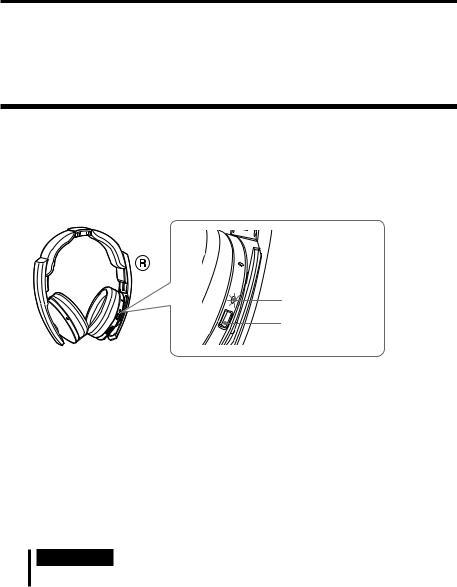
Checking the remaining battery power
To check the battery power, press and hold the POWER button about 2 seconds. The battery is still serviceable if the power indicator on the right housing lights up in green. Charge the rechargeable battery if the power indicator dims or flashes, or the sound becomes distorted or noisy.
Power indicator
POWER button
Power indicator
POWER button
12US Preparation

Connection
Connecting the Headphone System
Connecting the processor to digital components
Use the supplied optical digital connecting cable to connect the optical digital output jack on a BD/DVD device, digital satellite/TV receiver, GAME device or other digital component* to the DIGITAL IN jack of the processor.
The connected AV component may need to be set up for optical digital output. Refer to the operating instructions of the connected device.
Processor
 To DIGITAL IN jack
To optical digital output jack
Optical digital connecting cable (supplied)
Match the orientation of the plug with the jack, and then insert until the plug fits into place.
Notes
BD/DVD device, digital satellite/TV receiver, GAME device or other digital component having an optical digital output jack
The optical digital connecting cable is an extremely high-precision device and is sensitive to jolts and external pressure. Therefore, be careful when inserting and removing the cable plug.
The digital input for the processor does not support sampling frequencies of 32 kHz/96 kHz. Set the digital output setting of the BD/DVD device to 48 kHz/44.1 kHz when using this system. Noise may be heard when a 32 kHz/96 kHz digital signal is input. If this happen, connect an audio cord to the LINE IN (L/R) jacks, and enjoy the audio via the analog input.
*Connection to the optical digital output jack on your personal computer is not guaranteed to work with this system.
DTS
A DTS-compatible BD/DVD device is required for playback of BD/DVDs recorded in DTS audio. (For more details, refer to the operating instruction of your BD/DVD device.)
When playing CDs recorded in DTS format, noise may occur when fast forwarding or rewinding. This is not a malfunction.
If the DTS digital output is set to “OFF” on the BD/DVD device, no sound may be heard even if the DTS output is selected in the BD/DVD menu.
(Continued)
Connection 13US

Notes on optical digital connecting cable
Do not drop objects on the optical digital connecting cable or expose the cable to shock.
Grasp the plug to connect or disconnect the cable.
Be sure that the ends of the optical digital connecting cable are kept clean. Dust at the ends of the cable can degrade performance.
When storing the system, attach the cap to the end of the plug and be careful not to fold or bend the optical digital connecting cable with a bend radius less than 25 mm (1 inch).
The bend radius of the optical digital connecting cable should be no less than 25 mm (1 inch).
25 mm (1 inch)
Connecting the processor to analog components
Use an audio cord (sold separately) to connect the audio output jacks on a VCR, TV, or other component to the LINE IN (L/R) jacks on the processor.
Processor |
|
|
|
|
To audio output jacks |
VCR, TV, or other |
|
To LINE IN jacks |
component |
||
|
|||
|
|
||
Audio left |
Audio left |
|
|
(white) |
|
||
(L, white) |
|
||
|
|
||
Audio right (R, red) |
Audio right (red) |
||
Audio cord |
|
|
|
(sold separately)
Connecting cables (sold separately)
Use the connecting cable (stereo mini-plug pin plug 2) when connecting a stereo mini-jack (headphones jack, etc.) to the LINE IN jacks.
In this case, set the volume on the player at a medium level. Noise can occur if the volume on the player is set too low.
14US Connection
Setting the input level
If the volume is low using the analog input, set the ATT (attenuator) switch to “0 dB.”
|
ATT |
|
0dB |
|
-8dB |
Setting |
Connected components |
0 dB |
TV, portable components, and other components with a low output level |
–8 dB |
Other components (initial settings) |
Notes
Be sure to lower the volume before setting the ATT switch.
If audio input to the LINE IN jacks is distorted (sometimes, noise can be heard at the same time), set the ATT switch to “–8 dB.”
Connection 15US

Operation
Listening to a Connected Component
Before starting, be sure to read “Connecting the Headphone System” (pages 13 to 15) and make the proper connections.
1 Turn on the component connected to the processor.
BD/DVD device, digital satellite/ |
|
TV receiver, GAME device, or other |
POWER |
audio or video component |
2 Remove the headphones from the processor.
The processor turns on automatically. The processor automatically detects the optimum frequency for transmission according to your room conditions. Then the Decode Mode indicator lights up, depending on the audio signal input from the connected audio or video component.
Signal transmission system
This unit employs a proprietary transmission system using 2.4 GHz frequency. You can enjoy non-compressed sound with this wireless system.
3 Put on the headphones.
Press the POWER button for 2 seconds to turn on the headphones, the power indicator lights up in green.
Be sure to match the right and left side of the headphones with your ears. Adjust the headphones band to fit your ears.
There is a tactile dot on the left housing to distinguish the left side.
Tactile dot |
Power |
|
|
|
indicator |
16US Operation
Note
Use the headphones within the signal transmission range (page 21).
4 Slide the INPUT switch to select the component you want to listen to.
INPUT
DIGITAL 
ANALOG 
Position of switch |
Selected sound source |
DIGITAL |
Sound of the component connected to DIGITAL IN jack. |
ANALOG |
Sound of the component connected to LINE IN jacks. |
Note
To listen to dual audio (MAIN/SUB) sound sources, connect to the LINE IN jacks, and then select the sound source you want to listen to on the player, TV, or other component.
5 Start playback of the component selected in step 4.
6 Slide the switch to select the desired sound field, EFFECT or COMPRESSION. EFFECT switch
EFFECT
CINEMA
GAME 
VOICE (STEREO) 
OFF 
(Continued)
Operation 17US

Position of switch |
Sound field and suitable sound source |
OFF |
Normal playback of the headphones. |
VOICE (STEREO) |
Produces a clearer announcer’s voice. |
GAME |
Creates an accurate spatial sound and provides a clear sense of |
|
direction. Produces powerful and realistic sound for multi-channel |
|
surround sound video games. Suitable for video games with multi- |
|
channel sound sources. |
CINEMA |
Provides a surround-sound environment with a more natural sound |
|
quality (particularly in dialog). Produces a high sound quality that is |
|
found in the latest movie theaters. |
Notes
The volume of the headphones may vary, depending on the input signal and the setting of the EFFECT switch.
The surround sound effect may not be obtained from sound sources that do not incorporate video, such as music CDs.
This system simulates the average HRTF* common to most people. However, the effect can differ from person to person since the HRTF can vary between individuals.
* Head Related Transfer Function
COMPRESSION switch
COMPRESSION
ON 
OFF 
18US Operation

Position of switch |
Playback Effect |
OFF |
When the EFFECT switch is selected, the sound mode changes to the |
|
selected effect. |
ON |
This function maintains the overall level of program material: |
|
explosive sounds are attenuated while lower level sounds (dialog, etc.) |
|
are enhanced. |
|
Effective for audio signals with a wide dynamic range such as movies |
|
and classical music. |
Illustration of the compression process
|
explosion |
|
|
|
|
|
|
|
|
dynamic |
|
|
explosion |
|
input signal |
compression |
output signal |
|
|
|
|
|||
range |
dialogue |
|
dialogue |
standard |
|
|
|
|
|
|
|
|
whisper, background noise |
|
|
|
|
|
|
whisper, background noise
Dynamic range compression by built-in DSP processor
range dynamic
Startling level
Easy to hear level
Difficult to hear level
Decode Mode indicators
The processor automatically identifies the format of the input audio signal and the corresponding indicator lights up. Switch the audio between Dolby Digital, DTS, etc., on the connected equipment (BD/DVD device, digital satellite/TV receiver, etc.).
Dolby Digital: Input signal recorded in the Dolby Digital format.
Dolby PLIIx: Analog input signal, digital input PCM signal, or Dolby Digital signal processed by DOLBY PRO LOGIC IIx.
(If the EFFECT switch is set to “OFF” or “VOICE (STEREO),” it is not processed by DOLBY PRO LOGIC IIx.)
DTS: Input signal recorded in the DTS format.
Note
If the equipment connected to the DIGITAL IN jack is not playing back (fast forwarding, rewinding, etc.), the Decode Mode indicators may not light up correctly.
7 Adjust the volume.
To raise the volume, turn the VOL (Volume) control towards the tactile dot, and vice versa.
Tactile dot
Raise the volume
V O L
Lower the volume
(Continued)
Operation 19US

8
9
When you finished using the headphones, turn off the processor.
Press the / button on the processor to turn off the main power.
Place the headphones on the processor for charging.
Notes
When watching films, be careful not to raise the volume too high in quiet scenes. You may hurt your ears when a loud scene is played.
You may hear some noise when you disconnect the AC power adaptor from the processor before removing the headphones.
Transition time between modes
When sliding switches on the processor to change to new modes, the transition time between modes may vary. This is due to differences in system control between modes.
The power turns off automatically when you place the headphones on the processor
Charging will start automatically.
If a beep sound is heard from the headphones
A repeated beep sound is heard if the processor is not turned on or if the headphones are outside the RF signal transmission area. If you hear a beep sound, turn the processor on or move closer to the processor and use the headphones in the RF signal transmission area. If the beep sound does not stop even after turning the processor on or moving closer to the processor, the cause is likely to be interference from, for example, another wireless device using the 2.4 GHz wireless frequency band or electromagnetic waves generated from a microwave oven. Try taking the following measures.
Place the processor away from a device that generates electromagnet waves such as in a location in which a wireless LAN or other wireless device or microwave oven is used.
Point the antenna of the headphones towards the antenna of the processor’s direction, and make sure the signal is not blocked by any obstacles (page 21).
Change the installation location or position of the antenna of the processor, and move to a location in which sound can be heard from the headphones.
Install the processor outside of a rack, do not install it at the back of a rack.
Install the processor in a location where no metal is present, do not install it on a metal table.
Move the processor and headphones as close as possible to each other.
20US Operation
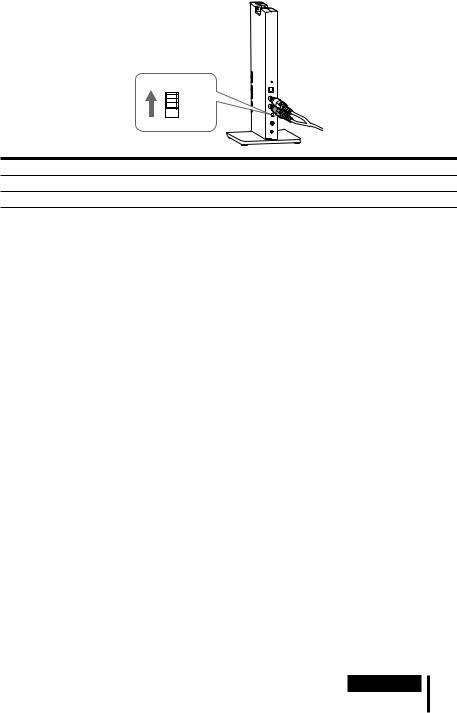
RF signal transmission area
The approximate RF signal transmission area from the processor to the headphones is up to 100 m but it varies depending on whether obstacles (human body, metal, wall, etc.) are present and the reception conditions.
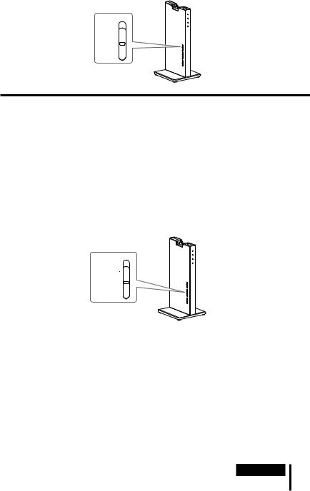
The antennas of this system are built into the parts indicated by the dotted lines in the illustration below.
Location of built-in
antenna Location of built-in antenna
If there are any obstacles between the antenna part of the processor and the antenna part of the headphones, the signal transmission range may become shorter. In such a case, ensure no obstacles are between the antennas of the processor and headphones.
The sound may be interrupted if you move out of the signal transmission range or the reception conditions around you deteriorate during use. The sound may also be interrupted as a result of obstacles, installation location or positioning of the processor and orientation of the headphones. This phenomenon is due to the characteristics of RF signals, and is not an indication of a malfunction.
Notes
This system uses a signal in the 2.4 GHz frequency band so use under the following conditions may affect the signal transmission range.
An obstacle such as a human body, metal, or wall is between the processor and headphones.
The processor is installed at the back of a rack.
In a location in which a wireless LAN has been built, in a location in which a microwave oven is used nearby or other electromagnetic waves are generated, etc.
In a location in which another wireless device uses the 2.4 GHz frequency band.
This system and a wireless LAN (IEEE802.11b/g) use the same frequency band (2.4 GHz) so use near a device incorporating a wireless LAN function will result in the generation of signal interference, which may cause the communication speed to deteriorate, and noise or sound interruption. In such a case, take the following measures.
When using the system within 10 m from a device incorporating a wireless LAN function, turn the wireless LAN function off.
Move the processor and headphones as close as possible to each other.
Do not install the processor near metal objects such as on a metal table.
The sound may be interrupted if the signal of this system is blocked by an obstacle. This phenomenon is due to the characteristics of RF signals, and is not an indication of a malfunction.
(Continued)
Operation 21US

If an audio signal is not input for about 30 mins
RF signal transmission from the processor automatically stops when an audio signal is not input for about 30 minutes. When the transmission stops, the processor’s power indicator blinks in green for 30 seconds and then turns off. RF signal transmission may stop when an extremely low sound is input for about 30 minutes. If this happens, raise the volume of the connected AV component as high as possible to the extent that the sound is not distorted and lower the volume of the headphones. If signal noise is output from a component connected to the AUDIO IN jacks, RF signal transmission may not stop.
If the processor is turned off
The headphones will turned off automatically after 5 minutes. When you want to use the system again, turn the headphones and processor on.
If you move out from the signal transmission range, the headphones cannot be connected to the system, and will turn off automatically after 5 minutes.
Note
The processor only works with its supplied headphones.
22US Operation

Replacing the Ear Pads
The ear pads are replaceable. If the ear pads become dirty or worn out, replace them as illustrated below. The ear pads are not commercially available. You can order replacements from the store where you purchased this system, or at your nearest Sony dealer.
1 Remove the old ear pad by pulling it off.
2 Place the new ear pad around the housing.
Operation 23US

Additional Information
Troubleshooting
If you run into any problems using this headphone system, use the following checklist. Should any problem persist, consult your nearest Sony dealer.
Symptom |
Cause and remedy |
No sound |
Check the connection between the processor and the AV component. |
|
Check that the connected AV component’s optical digital output is set to |
|
“ON” when selecting digital input. |
|
Turn on the AV component connected to the processor, and start the |
|
playback. |
|
Turn on the processor and headphones. |
|
Check that the INPUT switch on the processor is set to the component you |
|
want to listen to. |
|
If you connect the processor to an AV component using the headphones jack, |
|
raise the volume level on the connected AV component as high as possible to |
|
the extent that the sound is not distorted. |
|
Raise the headphones volume. |
|
The headphones’ power indicator goes off. |
|
Charge the rechargeable battery if it is weak. If the power indicator is still |
|
off after charging the battery, take the headphones to your nearest Sony |
|
dealer. |
|
You are trying to play a DTS audio track on a BD/DVD device that does not |
|
support DTS. |
|
Either use a BD/DVD device that supports DTS, or select a Dolby Digital |
|
or PCM audio track. |
|
You are playing back a BD/DVD disc recorded in DTS when DTS digital |
|
output setting for the BD/DVD device (including GAME device) is “OFF.” |
|
Refer to the operating instruction of your BD/DVD device, and change the |
|
DTS digital output setting to “ON.” |
|
You are playing back a BD/DVD disc recorded in DTS when the BD/DVD |
|
device (including GAME device) and the processor are analog-connected. |
|
Use the digital connection. (Analog sound may not be output from the |
|
BD/DVD device.) |
|
Set the sampling frequency of output signals for the device connected to |
|
the processor to 48 kHz/44.1 kHz. |
24US |
|
|
|
Additional Information |
|
|
|
|

Symptom |
Cause and remedy |
Distorted or intermittent sound (sometimes with noise)
Charge the rechargeable battery if it is weak. If the power indicator is still off after charging the battery, take the headphones to a Sony dealer.
Check if there is any wireless apparatus using 2.4 GHz frequency, or a microwave oven in the vicinity.
Change the position of the processor.
When analog input is selected, change the ATT switch on the processor to
“–8 dB.”
If you connect the processor to an AV component using the headphones jack, lower the volume level on the connected AV component.
When using DTS audio sources, set the EFFECT switch on the processor to “CINEMA” or “GAME” or “VOICE (STEREO)” mode (page 17, 18).
Set the sampling frequency of the output signal of any component connected to the processor to 48 kHz/44.1 kHz.
Low sound |
When analog input is selected, change the ATT switch on the processor to |
|
“0 dB.” |
|
If you connect the processor to an AV component using the headphones jack, |
|
raise the volume level on the connected AV component as high as possible to |
|
the extent that the sound is not distorted. |
|
Raise the headphones volume. |
|
|
Loud background noise |
If you connect the processor to an AV component using the headphones jack, |
|
raise the volume level on the connected AV component as high as possible to |
|
the extent that the sound is not distorted. |
|
Charge the rechargeable battery if it is weak. If the power indicator is still off |
|
after charging the battery, take the headphones to your nearest Sony dealer. |
|
Check if there is any wireless apparatus using 2.4 GHz frequency, or a |
|
microwave oven in the vicinity. |
The sound cuts off |
The processor stop transmitting if no signal is input for about 30 minutes. |
(When using analog input) |
Set the ATT switch on the processor to “0 dB.” |
|
If you connect the processor to an AV component using the headphones |
|
jack, raise the volume level on the connected AV component as high as |
|
possible to the extent that the sound is not distorted. |
|
|
The surround sound effect |
Set the EFFECT switch on the processor to “CINEMA” or “GAME” mode |
is not obtained |
(page 17, 18). |
|
The audio being played is not a multi-channel signal. |
|
The surround effect does not work for monaural sound sources. |
The Dolby Digital indicator The digital audio output setting for the BD/DVD device (including GAME
does not turn on |
device) may be set to “PCM.” |
|
Refer to the operating instruction of your BD/DVD device, and change the |
|
setting (such as “Dolby Digital/PCM” or “Dolby Digital”) for usage with |
|
components having built-in Dolby Digital decoders. |
|
Playback signals are not recorded in Dolby Digital format. |
|
The audio for the chapter being played is not a Dolby Digital signal. |
(Continued)
|
|
|
25US |
Additional Information |
|
||
|
|
|
|

Symptom |
Cause and remedy |
The Dolby PLIIx indicator |
The EFFECT switch on the processor is set to “OFF” or “VOICE (STEREO).” |
does not turn on |
When the INPUT switch is set to DIGITAL, PCM signal or Dolby Digital |
|
signal is not input. |
|
|
The Dolby PLIIx indicator |
The EFFECT switch on the processor is set to “CINEMA” or “GAME” mode. |
turns on |
Analog input signal, digital input PCM signal, Dolby Digital signal is input. |
The DTS indicator does not The DTS digital output setting on the BD/DVD device (including GAME
turn on |
device) is set to “OFF.” |
|
Refer to the operating instruction of your BD/DVD device, and change the |
|
DTS digital output setting to “ON.” |
|
Playback signals are not recorded in DTS format. |
|
The audio for the chapter being played is not a DTS signal. |
|
The BD/DVD device does not support DTS format. |
|
Use a BD/DVD device that supports DTS. |
|
|
The battery cannot be |
Check if the charging indicator turns on. If not, put the headphones on the |
charged |
processor correctly so that the charging indicator turns on. |
|
The processor’s contact pin and headphones’ contact point are dusty. |
|
Wipe them with a cotton bud, etc. |
The charging indicator |
The battery cannot be charged. |
blinks. |
You are attempting to charge the battery in an environment outside the |
|
recommended temperature range of between 5°C and 35°C (between 41°F |
|
and 95°F). You cannot charge while the charging indicator flashes. |
|
Charge in an environmental temperature of between 5°C and 35°C |
|
(between 41°F and 95°F). |
|
|
26US |
|
|
|
Additional Information |
|
|
|
|

Symptom |
Cause and remedy |
Other devices (wireless LAN, cordless phone, etc.) using 2.4 GHz frequency around the processor become unusable
If the wireless LAN uses the 2.4 GHz frequency, change the channel. If possible, use 5 GHz.
Keep the processor more than 2 m away from other devices (wireless LAN, cordless phone, etc.) using the 2.4 GHz frequency.
The signal transmission |
If there is a device with a wireless LAN function, other wireless device, or |
|
range is short (sound is |
a device that generates electromagnetic waves such as, for example, in a |
|
interrupted) |
location where a microwave oven is used, use the system away from that |
|
device. |
||
|
||
|
Orient the antenna of the headphones toward the antenna of the processor, |
|
|
and make sure the signal is not blocked by an obstacle (page 21). |
|
|
Install the processor at a different location or position, or change the place in |
|
|
which you listen with the headphones. |
|
|
If the processor is installed at the back of a rack, install it outside of the rack. |
|
|
If the processor is installed on a metal table, install it in a location where no |
|
|
metal is present. |
|
|
Move the processor and headphones as close as possible to each other. |
|
A repeated beep sounds |
The headphones cannot receive the signal from the processor. |
|
|
Move within the RF signal transmission area. |
|
|
Check the connection of the processor, AC power adaptor, and AC outlet. |
|
|
Check if there is any wireless apparatus using 2.4 GHz frequency, or a |
|
|
microwave oven around the processor and headphones. |
|
|
Change the position of the processor. |
|
|
There is no audio signal input for about 30 minutes and RF signals are not |
|
|
transmitted. |
The unit does not operate properly
Reset the unit. Pairing information is not deleted by this operation. Insert a small ball point pen, etc. into the hole, and push until you feel a click.
|
|
|
27US |
Additional Information |
|
||
|
|
|
|
 Loading...