


3-869-571-12 (1)
Digital
Videocassette
Recorder
Operating Instructions
Before operating the unit, please read this manual thoroughly and retain it for future reference.
The supplied CD-ROM includes Operating Instructions
for the DSR-series Digital Video Cassette Recorder or Player (English, Japanese, French, German, Italian and Spanish versions).
For more details, see “Using the CD-ROM Manual” on page 11.
DSR-1800A/1800AP
© 2005 Sony Corporation
Owner’s Record
The model and serial numbers are located at the rear. Record these numbers in the spaces provided below. Refer to them whenever you call upon your Sony dealer regarding this product.
Model No. |
|
Serial No. |
Important Safety Instructions
•Read these instructions.
•Keep these instructions.
•Heed all warnings.
•Follow all instructions.
•Do not use this apparatus near water.
•Clean only with dry cloth.
•Do not block any ventilation openings. Install in accordance with the manufacturer’s instructions.
•Do not install near any heat sources such as radiators, heat registers, stoves, or other apparatus (including amplifiers) that produce heat.
•Do not defeat the safety purpose of the polarized or grounding-type plug. A polarized plug has two blades with one wider than the other. A grounding-type plug has two blades and a third grounding prong. The wide blade or the third prong are provided for your safety. If the provided plug does not fit into your outlet, consult an electrician for replacement of the obsolete outlet.
•Protect the power cord from being walked on or pinched particularly at plugs, convenience receptacles, and the point where they exit from the apparatus.
•Only use attachments/accessories specified by the manufacturer.
•Use only with the cart, stand, tripod, bracket, or table specified by the manufacturer, or sold with the apparatus.
When a cart is used, use caution when moving the cart/apparatus combination to avoid injury from tip-over.
•Unplug this apparatus during lightning storms or when unused for long periods of time.
•Refer all servicing to qualified service personnel. Servicing is required when the apparatus has been damaged in any way, such as power-supply cord or plug is damaged, liquid has been spilled or objects have fallen into the apparatus, the apparatus has been exposed to rain or moisture, does not operate normally, or has been dropped.
WARNING
To prevent fire or shock hazard, do not expose the unit to rain or moisture.
To avoid electrical shock, do not open the cabinet. Refer servicing to qualified personnel only.
THIS APPARATUS MUST BE EARTHED.
CAUTION
The apparatus shall not be exposed to dripping or splashing. No objects filled with liquids, such as vases, shall be placed on the apparatus.
The unit is not disconnected from the AC power source (mains) as long as it is connected to the wall outlet, even if the unit itself has been turned off.
Television programs, films, video tapes and other materials may be copyrighted.
Unauthorized recording of such material may be contrary to the provisions of the copyright laws.
This symbol is intended to alert the user to the presence of uninsulated “dangerous voltage” within the product’s enclosure that may be of sufficient magnitude to constitute a risk of electric shock to persons.
This symbol is intended to alert the user to the presence of important operating and maintenance (servicing) instructions in the literature accompanying the appliance.
2

WARNING: THIS WARNING IS APPLICABLE FOR USA ONLY.
Using this unit at a voltage other than 120 V may require the use of a different line cord or attachment plug, or both. To reduce the risk of fire or electric shock, refer servicing to qualified service personnel.
For the customers in the USA (DSR-1800A only)
This equipment has been tested and found to comply with the limits for a Class A digital device, pursuant to Part 15 of the FCC Rules. These limits are designed to provide reasonable protection against harmful interference when the equipment is operated in a commercial environment. This equipment generates, uses, and can radiate radio frequency energy and, if not installed and used in accordance with the instruction manual, may cause harmful interference to radio communications. Operation of this equipment in a residential area is likely to cause harmful interference in which case the user will be required to correct the interference at his own expense.
You are cautioned that any changes or modifications not expressly approved in this manual could void your authority to operate this equipment.
All interface cables used to connect peripherals must be shielded in order to comply with the limits for a digital device pursuant to Subpart B of Part 15 of FCC Rules.
WARNING
Excessive sound pressure from earphones and headphones can cause hearing loss.
In order to use this product safely, avoid prolonged listening at excessive sound pressure levels.
For the customers in Europe (DSR-1800AP only)
This product with the CE marking complies with both the EMC Directive and the Low Voltage Directive issued by the Commission of the European Community.
Compliance with these directives implies conformity to the following European standards:
•EN60065: Product Safety
•EN55103-1: Electromagnetic Interference(Emission)
•EN55103-2: Electromagnetic Susceptibility(Immunity) This product is intended for use in the following Electromagnetic Environments:
E1 (residential), E2 (commercial and light industrial), E3 (urban outdoors), E4 (controlled EMC environment, ex. TV studio)
The manufacturer of this product is Sony Corporation, 1- 7-1 Konan, Minato-ku, Tokyo, Japan.
The Authorized Representative for EMC and product safety is Sony Deutschland GmbH, Hedelfinger Strasse 61, 70327 Stuttgart, Germany. For any service or guarantee matters please refer to the addresses given in separate service or guarantee documents.
For the customers in Taiwan only
3

AVERTISSEMENT
Afin de réduire les risques d’incendie ou d’électrocution, ne pas exposer cet appareil à la pluie ou à l’humidité.
Afin d’écarter tout risque d’électrocution, garder le coffret fermé. Ne confier l’entretien de l’appareil qu’à un personnel qualifié.
CET APPAREIL DOIT ÊTRE RELIÉ À LA TERRE.
ATTENTION
Eviter d’exposer l’appareil à un égouttement ou à des éclaboussures. Ne placer aucun objet rempli de liquide, comme un vase, sur l’appareil.
Cet appareil n’est pas déconnecté de la source d’alimentation secteur tant qu’il est raccordé à la prise murale, même si l’appareil lui-même a été mis hors tension.
Des programmes de télévision, films, bandes vidéo et autres peuvent être protégés par des droits d’auteur. L’enregistrement non autorisé de tels matériaux risque de constituer une violation de ces droits d’auteur.
AVERTISSEMENT
Une pression acoustique excessive en provenance des écouteurs ou du casque peut provoquer une baisse de l’acuité auditive.
Pour utiliser ce produit en toute sécurité, évitez l’écoute prolongée à des pressions sonores excessives.
Pour les clients européens (DSR-1800AP seulement)
Ce produit portant la marque CE est conforme à la fois à la Directive sur la compatibilité électromagnétique (EMC) et à la Directive sur les basses tensions émises par la Commission de la Communauté Européenne.
La conformité à ces directives implique la conformité aux normes européennes suivantes :
•EN60065: Sécurité des produits
•EN55103-1: Interférences électromagnétiques (émission)
•EN55103-2: Sensibilité électromagnétique (immunité) Ce produit est prévu pour être utilisé dans les environnements électromagnétiques suivants :
E1 (résidentiel), E2 (commercial et industrie légère), E3 (urbain extérieur) et E4 (environnement EMC contrôlé, ex. studio de télévision).
Le fabricant de ce produit est Sony Corporation, 1-7-1 Konan, Minato-ku, Tokyo, Japon.
Le représentant autorisé pour EMC et la sécurité des produits est Sony Deutschland GmbH, Hedelfinger Strasse 61, 70327 Stuttgart, Allemagne. Pour toute question concernant le service ou la garantie, veuillez consulter les adresses indiquées dans les documents de service ou de garantie séparés.
WARNUNG
Um die Gefahr von Bränden oder elektrischen Schlägen zu verringern, darf dieses Gerät nicht Regen oder Feuchtigkeit ausgesetzt werden.
Um einen elektrischen Schlag zu vermeiden, darf das Gehäuse nicht geöffnet werden. Überlassen Sie Wartungsarbeiten stets nur qualifiziertem Fachpersonal.
DIESES GERÄT MUSS GEERDET WERDEN.
ACHTUNG
Das Gerät ist nicht tropfund spritzwassergeschützt. Es dürfen keine mit Flüssigkeiten gefüllten Gegenstände, z. B. Vasen, darauf abgestellt werden.
Solange das Netzkabel an eine Netzsteckdose angeschlossen ist, bleibt das Gerät auch im ausgeschalteten Zustand mit dem Strommetz verbunden.
Fernsehprogramme, Filme, Videobänder usw. können urheberrechtlich geschützt sein. Unerlaubtes Aufnehmen solcher Materialien verstößt gegen das Urheberrecht.
WARNUNG
Zu hoher Schalldruck von Ohrhörern und Kopfhörern kann Gehörschäden verursachen.
Um dieses Produkt sicher zu verwenden, vermeiden Sie längeres Hören bei sehr hohen Schalldruckpegeln.
Für Kunden in Europa (Nur DSR-1800AP)
Dieses Produkt besitzt die CE-Kennzeichnung und erfüllt die EMV-Richtlinie sowie die Niederspannungsrichtlinie der EG-Kommission.
Angewandte Normen:
•EN60065: Sicherheitsbestimmungen
•EN55103-1: Elektromagnetische Verträglichkeit (Störaussendung)
•EN55103-2: Elektromagnetische Verträglichkeit (Störfestigkeit)
4

Für die folgenden elektromagnetischen Umgebungen: E1 (Wohnbereich), E2 (kommerzieller und in beschränktem Maße industrieller Bereich), E3 (Stadtbereich im Freien) und E4 (kontrollierter EMVBereich, z.B. Fernsehstudio).
Der Hersteller dieses Produkts ist Sony Corporation, 1-7-1 Konan, Minato-ku, Tokyo, Japan.
Der autorisierte Repräsentant für EMV und Produktsicherheit ist Sony Deutschland GmbH, Hedelfinger Strasse 61, 70327 Stuttgart, Deutschland. Bei jeglichen Angelegenheiten in Bezug auf Kundendienst oder Garantie wenden Sie sich bitte an die in den separaten Kundendienstoder Garantiedokumenten aufgeführten Anschriften.
1.Für Ihren privat genutzten Videorecoder muß eine Fernseh-Rundfunk-Genehmigung beantragt werden, sofern nicht bereits eine Genehmigung für ein Fernsehgerät desselben Haushaltes vorliegt. Im geschäftlichen Bereich ist jeder einzelne Videorecorder anmeldeund gebührenpflichtig. (Auskunft ggf. bei der GEZ oder den Rundfunkanstalten.)
2.Im privaten Bereich ist die Aufzeichnung von urheberrechtlich geschützten Werken auf Bildund Tonträger gestattet. Die entsprechenden Urheber-Vergütungen sind im Kaufpreis des Gerätes enthalten. Öffentliche Wiedergabe oder Verbreitung von mitgeschnittenen Fernsehsendungen ist ohne Erlaubnis nicht zulässig, verpflichtet zu Schadenersatz und ist gegebenenfalls strafbar.
3.Im Rahmen der Regelung des §47 des Urheberrechtsgesetzes sind Aufzeichnungen von Schulfernsehprogrammen gestattet. Mitschnitte von Schulfunksendungen dürfen jedoch nur für den Unterricht verwendet werden und sind spätestens am Ende des laufenden Schuljahres zu löschen.
ATTENZIONE
Per ridurre il rischio di incendi o scosse elettriche, non esporre questo apparato alla pioggia o all’umidità.
Per evitare scosse elettriche, non aprire l’involucro. Per l’assistenza rivolgersi unicamente a personale qualificato.
QUESTO APPARECCHIO DEVE ESSERE MESSO A TERRA.
ATTENZIONE
L’apparecchio non deve essere esposto a gocciolamenti o spruzzi. Non collocare sull’apparecchio oggetti contenenti liquidi, come ad esempio vasi di fiori.
AVVERTIMENTO
L’apparecchio non è scollegato dalla fonte di alimentazione CA (corrente di rete) fintanto che è collegato ad una presa di corrente, anche se l’apparecchio stesso è stato spento.
Programmi televisivi, film, videonastri e altro materiale possono essere tutelati dai diritti d’autore. Registrazioni non autorizzate di tali materiali possono infrangere la legge sui diritti d’autore.
AVVERTENZA
Un’eccessiva pressione sonora da auricolari e cuffie può causare la perdita dell’udito.
Per usare questo prodotto in maniera sicura, evitare l’ascolto prolungato a livelli eccessivi di pressione sonora.
Per i clienti in Europa (DSR-1800AP soltanto)
Questo prodotto recante il marchio CE è conforme sia alla direttiva sulla compatibilità elettromagnetica (EMC) che alla direttiva sulle basse tensioni emesse dalla Commissione della Comunità Europea.
La conformità a queste direttive implica la conformità alle seguenti normative europee:
•EN60065: Sicurezza dei prodotti
•EN55103-1: Interferenza elettromagnetica (Emissione)
•EN55103-2: Sensibilità ai disturbi elettromagnetici (Immunità)
Questo prodotto è destinato all’uso nei seguenti ambienti elettromagnetici:
E1 (residenziali), E2 (commerciali e industriali leggeri),
E3 (esterni urbani) e E4 (ambienti EMC controllati, ad esempio studi televisivi).
5

Il fabbricante di questo prodotto è la Sony Corporation, 1- 7-1 Konan, Minato-ku, Tokyo, Giappone.
La rappresentanza autorizzata per EMC e la sicurezza dei prodotti è la Sony Deutschland GmbH, Hedelfinger Strasse 61, 70327 Stoccarda, Germania. Per qualsiasi questione riguardante l’assistenza o la garanzia, si prega di rivolgersi agli indirizzi riportati nei documenti sull’assistenza o sulla garanzia a parte.
ADVERTENCIA
Para reducir el riesgo de electrocución, no exponga este aparato a la lluvia ni a la humedad.
Para evitar descargas eléctricas, no abra el aparato. Solicite asistencia técnica únicamente a personal especializado.
ESTE APARATO DEBE CONECTARSE A TIERRA.
PRECAUCIÓN
No se debe exponer la unidad a goteos o salpicaduras. Tampoco se deben colocar sobre la misma objetos llenos de líquido, tales como un florero.
La unidad no queda desconectada de la alimentación eléctrica siempre que esté conectado al tomacorriente incluso aunque se desconecte el interruptor principal.
Los programas de televisión, las películas, las cintas de vídeo y material similar pueden estar protegidos por las leyes de copyright.
La grabación no autorizada de dicho material puede ir en contra de lo establecido por las leyes de copyright.
ADVERTENCIA
Una excesiva presión de sonido de los auriculares y cascos auriculares puede provocar una pérdida de percepción de sus oídos.
Para utilizar este producto con seguridad, no escuche durante mucho tiempo con niveles de presión de sonido excesivos.
Para los clientes de Europa (DSR-1800AP sólo)
Este producto con marcado CE cumple con las directivas de compatibilidad electromagnética y baja tensión de la Comisión Europea.
El cumplimiento de estas directivas implica la conformidad con los siguientes estándares europeos:
•EN60065: Seguridad del producto
•EN55103-1: Interferencia electromagnética (Emisión)
•EN55103-2: Susceptibilidad electromagnética
(Inmunidad)
Este producto está ha sido diseñado para utilizarse en los entornos electromagnéticos siguientes:
E1 (zona residencial), E2 (zona comercial e industrial ligera), E3 (exteriores urbanos), y E4 (entorno con EMC controlada, p. ej., estudio de televisión).
El fabricante de este producto es Sony Corporation, con dirección en 1-7-1 Konan, Minato-ku, Tokio, Japón.
El Representante autorizado para EMC y seguridad del producto es Sony Deutschland GmbH, Hedelfinger Strasse 61, 70327 Stuttgart, Alemania. Para asuntos relacionados con el servicio y la garantía, consulte las direcciones entregadas por separado para los documentos de servicio o garantía.
6

Table of Contents
Chapter 1 Overview |
|
Features................................................................................. |
9 |
DVCAM Format ....................................................................... |
9 |
A Wealth of Interfaces ............................................................ |
10 |
Facilities for High-Efficiency Editing..................................... |
10 |
Other Features ......................................................................... |
10 |
Optional Accessories............................................................... |
11 |
Using the CD-ROM Manual ................................................ |
11 |
CD-ROM System Requirements............................................. |
11 |
Preparations............................................................................. |
11 |
Reading the CD-ROM Manual ............................................... |
11 |
Location and Function of Parts......................................... |
13 |
Front Panel .............................................................................. |
13 |
Rear Panel ............................................................................... |
21 |
Chapter 2 Recording and Playback |
|
Usable Cassettes................................................................ |
27 |
Inserting and Ejecting Cassettes ............................................. |
29 |
Recording............................................................................ |
31 |
Settings for Recording ............................................................ |
31 |
Recording Procedure............................................................... |
34 |
Playback .............................................................................. |
37 |
Settings for Playback .............................................................. |
37 |
Playback Procedure................................................................. |
38 |
Repeat Playback—Automatic Cyclical Playback ................... |
40 |
Setting Points A and B for Repeat Playback........................... |
40 |
Cuing Up to Any Desired Position Set as Point A or B.......... |
45 |
Chapter 3 Convenient Functions for Editing Operation |
|
Setting the Time Data......................................................... |
47 |
Displaying Time Data and Operation Mode Indications ........ |
47 |
Using the Internal Time Code Generator................................ |
49 |
Synchronizing Internal and External Time Codes .................. |
50 |
Rerecording the Time Code—TC Insert Function.................. |
51 |
High-Speed and Low-Speed Search—Quickly and |
|
Accurately Determining Editing Points ..................... |
53 |
Search Operations via External Equipment ............................ |
53 |
Search Operations on This Unit .............................................. |
53 |
Digitally Dubbing Signals in DVCAM Format................... |
55 |
Table of Contents |
7 |
|
|

Chapter 4 Menu Settings |
|
Menu Organization ............................................................. |
59 |
Menu Contents.................................................................... |
62 |
Setup Menu ............................................................................. |
62 |
Auto Mode (AUTO FUNCTION) Execution Menu............... |
75 |
Changing Menu Settings ................................................... |
76 |
Buttons Used to Change Settings............................................ |
76 |
Changing the Settings of Basic Items ..................................... |
76 |
Displaying Enhanced Items .................................................... |
78 |
Changing the Settings of Enhanced Items .............................. |
78 |
Returning Menu Settings to Their Factory Default Settings... |
79 |
Displaying Supplementary Status Information................ |
80 |
Chapter 5 Connections and Settings |
|
Connections for a Digital Non-Linear Editing System .... |
83 |
Connections for a Cut Editing System ............................. |
85 |
Connections for an A/B Roll Editing System................... |
86 |
Connections for Analog Recording .................................. |
91 |
Adjusting the Sync and Subcarrier Phases ..................... |
92 |
Chapter 6 Maintenance and Troubleshooting |
|
Maintenance........................................................................ |
95 |
Condensation........................................................................... |
95 |
Regular Checks ....................................................................... |
95 |
Head Cleaning......................................................................... |
97 |
Troubleshooting ................................................................. |
98 |
Error Messages...................................................................... |
100 |
Alarm Messages.................................................................... |
100 |
Appendixes
Precautions ....................................................................... |
103 |
Specifications ................................................................... |
104 |
Glossary ............................................................................ |
107 |
Index .................................................................................. |
109 |
8 Table of Contents

Overview Chapter 1
Features
The DSR-1800A/1800AP is a 1/4-inch digital video cassette recorder using the DVCAM digital recording format. It achieves stable, superb picture quality by digitally processing video signals separated into color difference signals and luminance signals (component method).
The unit is equipped with a variety of functions needed for videocassette recorders and players used in professional digital video editing systems.
The unit is also equipped with an i.LINK interface, thus enabling simple connection with a nonlinear editing* system supporting DV format.
Furthermore, the unit is equipped with a full-fledged analog interface to support hybrid systems that combine conventional analog equipment with digital equipment.
*Non-linear editing: This is an editing method that uses video and audio signals digitally encoded and recorded on a hard disk as digital data. When compared with conventional (linear) editing methods, non-linear editing offers vastly improved efficiency in editing operations, for example, by eliminating tape transport time.
The main features of the unit are described in the following.
DVCAM Format
DVCAM is based on the consumer DV format, which uses the 4:1:1 component digital format, and provides a 1/4-inch digital recording format for professional use.
High picture quality, high stability
Video signals are separated into color difference signals and luminance signals, which are encoded and compressed to one-fifth size before being recorded to ensure stable and superb picture quality.
Because the recording is digital, multi-generation dubbing can be performed with virtually no deterioration of quality.
Wide track pitch
The recording track pitch is 15 µm, fully 50 percent wider than the 10-µm track pitch of the DV format. Thanks to this feature, the DVCAM format sufficiently meets the reliability and precision requirements of professional editing.
High-quality PCM digital audio
PCM recording makes for a wide dynamic range and a high signal-to-noise ratio, thereby enhancing sound quality.
There are two recording modes: 2-channel mode (48-kHz sampling and 16-bit quantization), which offers sound quality equivalent to the DAT (Digital Audio Tape) format, or 4-channel mode (32-kHz sampling and 12-bit quantization).
Playback compatibility with DV and DVCPRO formats
A DV cassette recorded on a DV format VCR (excluding the tapes recorded in LP mode) as well as a DVCPRO (25M) format recorded cassette can be played back on this unit.
Note
When playing back a tape recorded in DVCPRO (25M) format, the i.LINK output (see “Digital interfaces” on page 10) of this unit is subjected to muting. Furthermore, it is not possible to play back the cue-audio track of the tape.
Features 9

Overview 1 Chapter
Support for three cassette sizes
There are two sizes of DVCAM cassette: standard and mini. You can use either size with this unit.
The unit also accepts L and M sizes of DVCPRO cassette.
•When a cassette is inserted, the reel mechanism of the unit automatically adjusts to the size of the inserted cassette.
•The capacity of a standard cassette is 184 minutes of recording/playback, and that of a mini cassette is 40 minutes.
A Wealth of Interfaces
Digital interfaces
i.LINK (DV)*: The unit can input and output digital video and audio signals in DV format.
*i.LINK and  are trademarks and indicate that this product is in agreement with IEEE1394-1995 specifications and their revisions.
SDI (serial digital interface)/AES/EBU (optional DSBK-1801 SDI/AES/EBU Input/Output Board):
When the unit is fitted with the optional DSBK-1801 board, it can input and output D1 (component) format digital video and audio signals and also AES/EBUformat digital audio signals.
Remote control
The unit can be operated by remote control from an editing control unit that supports the RS-422A interface or from an optional SIRCS*-compatible remote control unit such as the DSRM-10.
*SIRCS (Sony Integrated Remote Control System): A command protocol to remote control Sony professional videocassette recorders/players.
Playback control using search dial
The search dial on the front panel of the unit allows you to carry out playback operation in jog or shuttle mode without requiring an external editing control unit or remote control unit to be connected to the unit.
High-speed search function
You can carry out color picture searches during fast forward and rewind at speeds up to 85 times normal speed. When remote-controlling this unit in shuttle mode from an editing control unit or a remote control unit, you can search at any speed in the range 0 (still) to 60 times normal speed in both directions. You can also search frame-by-frame in jog mode.
At search speeds up to 10 times normal speed in both directions, you can also hear playback audio.
Analog interfaces
The unit also comes with analog interfaces enabling it to be connected to analog video and audio equipment.
Analog video: These interfaces include a component interface, composite interface, and S-video interface.
Analog audio: Four channels each of input and output are provided. It is also possible to connect a microphone to the unit.
Facilities for High-Efficiency Editing
The unit provides an abundance of functions that enhance editing efficiency and precision.
Cross-fade editing
For audio editing, you can select from cut-in editing, fade- in/fade-out editing, and cross-fade editing.
Internal time code generator and reader
An internal time code generator and reader enables time code compliant with SMPTE (for DSR-1800A)/EBU (DSR-1800AP) format to be recorded and played back. This allows editing to single frame precision. Outputting or inputting time code (LTC) to or from an
external device is also possible using the TIME CODE IN/ OUT connectors.
The unit is also compatible with VITC.
Digital slow-motion playback
Using the frame memory function, the unit can show noise-free slow-motion playback at speeds ranging from 0 to 1/2 times normal speed in both directions.
Digital jog sound function
When searching at speeds in the range +1 to +1/30 or −1/30 to −1* times normal speed, the digital jog sound function is enabled. The audio signal is saved in temporary memory, and replayed according to the search speed. This allows searching on the sound track.
*The positive direction refers to forward movement of the tape, and the negative direction to reverse movement.
Video process control
For analog video output and SDI-format video output, you can adjust the video output level, chroma signal output level, setup level (for DSR-1800A), black level (for DSR1800AP), and chroma phase.
Other Features
Menu system for functionality and operation settings
The unit provides a menu system to make its various functions easier to use and set up its operation conditions.
10 Features
Superimposition function
Time code values, operation mode indications, error messages, and other text data can be superimposed and output in analog composite video signals.
Easy maintenance functions
Self-diagnostic/alarm function: This function automatically detects setup and connection errors, operation faults, and other problems. It also displays a description of the problem, its cause, and the recommended response on the video monitor screen or time counter display.
Digital hours meter: The digital hours meter functions include four kinds of tally operations for operating hours, head drum usage hours, tape transport hours, and tape threading/unthreading times. The tally results can be viewed on the video monitor or the time counter display.
Compatible with wide-screen aspect ratio (16:9)
The unit can record and play back aspect ratio information. When video accompanied by wide-screen aspect ratio information is recorded or played back, the unit can output the video signal also containing the aspect ratio information.
Rack mountable
When you use an optional rack mount kit, you can mount this unit onto an EIA-standard 19-inch rack (height = 4 units).
Optional Accessories
DSBK-1801 SDI/AES/EBU Input/Output
Board
When installed in the unit, this optional board enables digital video and audio signals in the D1 format and also AES/EBU-format digital audio signals to be transferred between this unit and digital Betacam VCRs or other digital equipment.
RMM-131/1 Rack Mount Kit
This kit can be used to mount the unit onto an EIAstandard 19-inch rack.
Using the CD-ROM
Manual
The supplied CD-ROM includes Operating Instructions for the DSR-series Digital Video Cassette Recorder or Player (English, Japanese, French, German, Italian and Spanish versions).
CD-ROM System Requirements
The following are required to access the supplied CDROM disc.
•Computer: PC with Intel Pentium CPU
-Installed memory: 64 MB or more
-CD-ROM drive: × 8 or faster
•Monitor: Monitor supporting resolution of 800 × 600 or higher
•Operating system: Microsoft Windows XP Professional or Windows XP Home Edition
When these requirements are not met, access to the CDROM disc may be slow, or not possible at all.
Preparations
One of the following programs must be installed on your computer in order to use the Operating Instructions contained on the CD-ROM disc.
•Adobe Acrobat Reader Version 4.0 or higher
•Adobe Reader Version 6.0 or higher
Note
If Adobe Reader is not installed, you can download it from the following URL:
http://www.adobe.com/
Reading the CD-ROM Manual
To read the Operating Instructions contained on the CDROM disc, do the following.
1 Insert the CD-ROM disc in your CD-ROM drive.
A cover page appears automatically in your browser. If it does not appear automatically in the browser, double-click the index.htm file on the CD-ROM disc.
2 Select and click the Operating Instructions that you want to read.
This opens the PDF file of the Operating Instructions.
Overview 1 Chapter
Using the CD-ROM Manual 11

Overview 1 Chapter
Note
If you lose the CD-ROM disc or become unable to read its content, for example because of a hardware failure, you can do one of the following.
•You can purchase a new CD-ROM disc to replace one that has been lost or damaged. Contact your Sony service representative.
•You can purchase printed versions of the Operating Instructions (English version). Contact your Sony service representative.
When ordering, be sure to specify the part number of the manual you want.
Part No. |
Models covered |
3-869-571-1X DSR-1800A/1800AP
•Intel and Pentium are registered trademarks of Intel Corporation or its subsidiaries in the United States and other countries.
•Microsoft and Windows are registered trademarks of Microsoft Corporation in the United States and/or other countries.
•Adobe, Acrobat, and Adobe Reader are trademarks of Adobe Systems Incorporated in the United States and/or other countries.
12 Using the CD-ROM Manual

Location and Function of Parts
Front Panel
a POWER switch
b Audio level meters
AInput selection/audio mode display section (see page 14)
c Cassette compartment
POWER
dB |
OVER dB |
dB |
OVER dB |
dB |
OVER dB |
dB |
OVER dB |
INPUT |
|
|
|
i.LINK |
|
0 |
0 |
0 |
0 |
0 |
0 |
0 |
0 |
|
|
|
|
||
|
|
|
|
|
|
|
|
|
|
||||
-12 |
1 |
-12 |
1 |
-12 |
1 |
-12 |
1 |
VIDEO |
COMPOSITE |
Y-R,B S VIDEO SDI |
SG |
||
-20 |
0 |
-20 |
0 |
-20 |
0 |
-20 |
0 |
CH11/2 |
ANALOG |
AES/EBU |
SDI |
SG |
|
-30 |
-1 |
-30 |
-1 |
-30 |
-1 |
-30 |
-1 |
AUDIO |
ANALOG |
AES/EBU |
SDI |
SG |
|
|
|
|
|
CH23/4 |
|||||||||
-40 |
-2 |
-40 |
-2 |
-40 |
-2 |
-40 |
-2 |
|
|
|
|
|
|
-60 |
1 |
-60 |
2 |
-60 |
3 |
-60 |
4 |
PB FS |
48k44.1k32k |
REC MODE |
2CH4CH |
||
A 
 B
B
MARK
BMenu control panel (inside of the door) (see page 15)
g AUDIO INPUT LEVEL control knobs
f CONTROL S connector
e HEADPHONES connector
d PHONE LEVEL control knob
FRemote control setting section (see page 20)
ESearch control section
(see page 19)
DDisplay section (see page 18)
CTape transport control section (see page 17)
a POWER switch
Press the “ ” side to power the unit on. When the unit is powered on, the display windows in the front panel lights. To power the unit off, press the “  ” side of the switch.
b Audio level meters
These show the audio levels of channels 1 to 4 (recording levels in recording mode or E-E mode* and playback level in playback mode).
*E-E mode: Abbreviation of “Electric-to-Electric mode.” In this mode, video and audio signals input to the VCR are output after passing through internal electric circuits, but not through magnetic conversion circuits such as heads and tapes. This can be used to check input signals and for adjusting input signal levels.
c Cassette compartment
Accepts DVCAM, DV and DVCPRO (25M) videocassettes.
For details of usable cassettes, see page 27.
d PHONE LEVEL control knob
Controls the volume of the headphones connected to the HEADPHONES connector.
Overview 1 Chapter
Location and Function of Parts |
13 |
|
|
Overview 1 Chapter
e HEADPHONES connector (stereo phone jack)
Connect stereo headphones for headphone monitoring during recording or playback.
The audio signal you want to monitor can be selected with the MONITOR SELECT switches on the menu control panel.
f CONTROL S connector (stereo minijack)
Connect a SIRCS-compatible remote control unit such as the DSRM-10.
g AUDIO INPUT LEVEL control knobs
When recording, you can use these knobs to set audio input levels for CH-1 (channel 1), CH-2, CH-3 and CH-4, respectively.
You can make these knobs inoperative with the REC LEVEL menu item (see page 70).
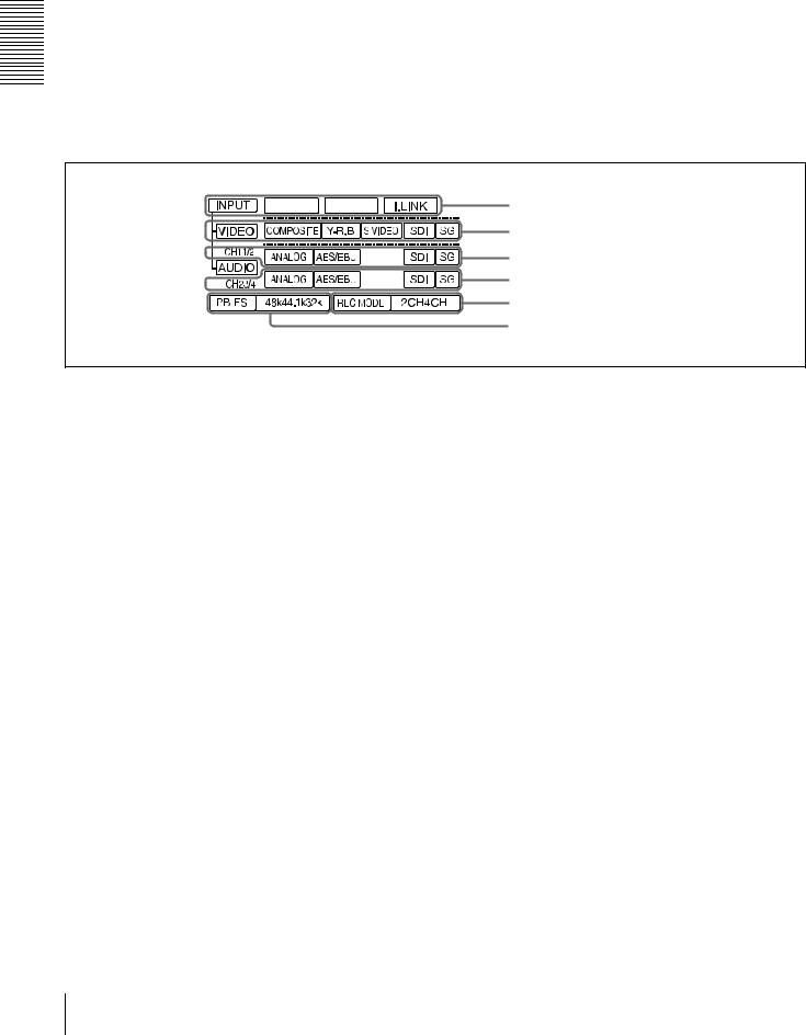
A Input selection/audio mode display section
a INPUT display
b VIDEO display
c AUDIO CH1 1/2 display
d AUDIO CH2 3/4 display
e REC MODE display
f PB FS display
a INPUT display
i.LINK: When you press the SDTI/i.LINK button in the INPUT SELECT section, the i.LINK indicator lights. This indicates that digital video and audio signals in i.LINK-compatible DV format are currently selected.
b VIDEO display
Indicates the input video signal selected with the VIDEO IN button in the INPUT SELECT section. COMPOSITE: Composite video signal
Y−R, B: Y, R−Y and B−Y component video signals S VIDEO: S-video signal
SDI: SDI video signal (optional DSBK-1801 board required)
SG: Video test signal
c AUDIO CH1 1/2 display
Indicates the input audio signal selected with the CH-1,1/2 button in the INPUT SELECT section.
ANALOG: Analog audio signal
AES/EBU: Digital audio signal in AES/EBU format (optional DSBK-1801 board required)
SDI: SDI audio signal (optional DSBK-1801 board required)
SG: Audio test signal
d AUDIO CH2 3/4 display
Indicates the input audio signal selected with the CH-2,3/4 button in the INPUT SELECT section. The indications available are the same as for the AUDIO CH1 1/2 display described above.
e REC MODE (audio recording mode) display
Indicates the audio recording mode (2CH or 4CH) selected with the REC MODE menu item (see page 69).
fPB FS (playback audio sampling frequency) display
Indicates the sampling frequency (48 kHz, 44.1 kHz or 32 kHz) at which audio is recorded on tape.
14 Location and Function of Parts
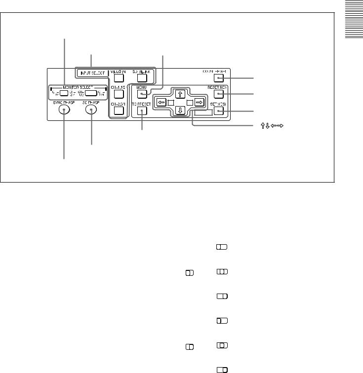
BMenu control panel
The menu control panel is located on the inside of the door at the lower front of the unit. Pull the top of the door to open it.
a MONITOR SELECT switches
b INPUT SELECT section c MENU button
|
|
d COUNTER SEL button |
|
MIX |
|
e RESET (NO) button |
|
|
|
|
|
A |
B |
|
|
|
MARK |
f SET (YES) button |
|
|
|
|
|
|
|
g |
buttons |
hTC PRESET button
i SC PHASE control
j SYNC PHASE control
a MONITOR SELECT switches
Use these switches to select the channels for audio output via the AUDIO MONITOR OUT connector on the rear panel and the HEADPHONES connector on the front panel.
Use the left switch to select the basic channel setting, then use the right switch to select the output format (monaural, stereo, or mix).
The following table lists the correspondence of left/right switch settings and channel/output format selections.
Switch setting |
|
Selected channel and output |
||||
|
|
|
|
format |
|
|
|
|
|
|
|
|
|
Left |
|
Right |
|
HEADPHONES |
AUDIO |
|
switch |
|
switch |
|
connector |
MONITOR OUT |
|
|
|
|
|
|
connector |
|
|
|
|
|
|
|
|
|
|
CH- |
CH- |
Channel 1 only |
Channel 1 only |
|
|
|
(monaural) |
(monaural) |
|||
|
|
1/3 |
2/4 |
|||
|
|
MIX |
|
|
|
|
|
|
|
|
|
|
|
|
|
CH- |
CH- |
Channels 1 and |
Channels 1 and |
|
CH- |
CH- |
2 (stereo) |
2 (mix) |
|||
1/3 |
2/4 |
|||||
1/2 |
3/4 |
|||||
|
|
MIX |
|
|
|
|
|
|
|
|
|
|
|
|
|
CH- |
CH- |
Channel 2 only |
Channel 2 only |
|
|
|
(monaural) |
(monaural) |
|||
|
|
1/3 |
2/4 |
|||
|
|
MIX |
|
|
|
|
|
|
|
|
|
|
|
|
|
CH- |
CH- |
Channel 3 only |
Channel 3 only |
|
|
|
(monaural) |
(monaural) |
|||
|
|
1/3 |
2/4 |
|||
|
|
MIX |
|
|
|
|
|
|
|
|
|
|
|
|
|
CH- |
CH- |
Channels 3 and |
Channels 3 and |
|
1/2 |
3/4 |
4 (stereo) |
4 (mix) |
|||
1/3 |
2/4 |
|||||
CH- |
CH- |
|
|
|
|
|
|
|
MIX |
|
|
|
|
|
|
|
|
|
|
|
|
|
CH- |
CH- |
Channel 4 only |
Channel 4 only |
|
|
|
(monaural) |
(monaural) |
|||
|
|
1/3 |
2/4 |
|||
|
|
MIX |
|
|
|
|
|
|
|
|
|
|
|
Overview 1 Chapter
Location and Function of Parts |
15 |
|
|

Overview 1 Chapter
b INPUT SELECT section
VIDEO IN button
Each press of this button cycles through the following input video signal selection options.
•Composite video signal input to the VIDEO IN connectors
•Component video signals input to the COMPONENT VIDEO IN connectors
•S-video signal input to the S VIDEO IN connector
•SDI video signal input to the SDI IN connector (optional DSBK-1801 board required)
•Video test signal (selected with the INT VIDEO SG menu item (see page 68) generated by the internal signal
generator
In the input selection/audio mode display section, the VIDEO display shows the selection made with this button.
CH1,1/2 (audio channel 1 or 1/2) button
Each press of this button cycles through the following input audio signal selection options for audio channel 1 (when in 2-channel mode) or for audio channels 1 and 2 (when in 4-channel mode).
•Analog audio signal(s) input to the AUDIO IN CH-1 connector (when in 2-channel mode) or AUDIO IN CH- 1 and CH-2 connectors (when in 4-channel mode)
•Digital audio signal in AES/EBU format input to the DIGITAL AUDIO (AES/EBU) IN CH-1/2 connector (optional DSBK-1801 board required)
•SDI audio signal input to the SDI IN connector (optional DSBK-1801 board required)
•Audio test signal (selected with the INT AUDIO SG
menu item (see page 71)) generated by the internal signal generator
In the input selection/audio mode display section, the AUDIO CH1 1/2 display shows the selection made with this button.
CH2,3/4 (audio channel 2 or 3/4) button
Each press of this button cycles through the input audio signal selection options for audio channel 2 (when in 2- channel mode) or for audio channels 3 and 4 (when in 4- channel mode). The input audio signal selection options corresponding to those for the CH1,1/2 button described above are available.
In the input selection/audio mode display section, the AUDIO CH2 3/4 display shows the selection made with this button.
SDTI/i.LINK (SDTI(QSDI) interface/i.LINK selection) button
Selects digital video and audio signals in i.LINKcompatible DV format, input to the  DV IN/OUT connector. When you press this button, the i.LINK indicator lights in the input selection/audio mode display section.
c MENU button
Press this button to display the menu on the monitor screen and the time counter display. Press it again to return from the menu display to the usual display.
On how to use the menu, see Chapter 4 “Menu Settings.” (see page 59)
d COUNTER SEL (selection) button
Selects the type of time data to be shown in the time counter display. Each press of this button cycles through three indicator display options: COUNTER (CNT: count value of the time counter), TC (time code), and U-BIT (user bits).
Note
When the REMOTE button in the remote control setting section is lit, the COUNTER SEL button does not operate. In this case, make the time data selection via the remote equipment that is connected to the REMOTE connector on the rear panel.
e RESET (NO) button
Press this button to:
•reset menu settings,
•reset the time count (COUNTER) shown in the time counter display to zero, or
•send a negative response to the prompts issued by the unit.
f SET (YES) button
Press this button to:
•save new settings, such as selected menu items and time code settings, to the memory of the unit, or
•send a positive response to the prompts issued by the unit.
g Arrow (JjKk) buttons
Use these buttons to move around the menu items, and also for setting time code and user bit data.
For details on setting time code and user bit data, see “Using the Internal Time Code Generator” on page 49.
h TC (time code) PRESET button
Use this button when setting an initial time code value and user bit data.
For details on setting time code and user bit data, see “To set the initial time code value and user bit data” on page 49.
i SC (subcarrier) PHASE control
Turn this control to accurately adjust the subcarrier phase of the composite video output signal of the unit with respect to the reference video signal. Use a cross-point (Phillips) screwdriver to turn it.
16 Location and Function of Parts
j SYNC (synchronization) PHASE control |
the reference video signal. Use a cross-point (Phillips) |
Turn this control to accurately adjust the synchronization |
screwdriver to turn it. |
phase of the output video signal of the unit with respect to |
|
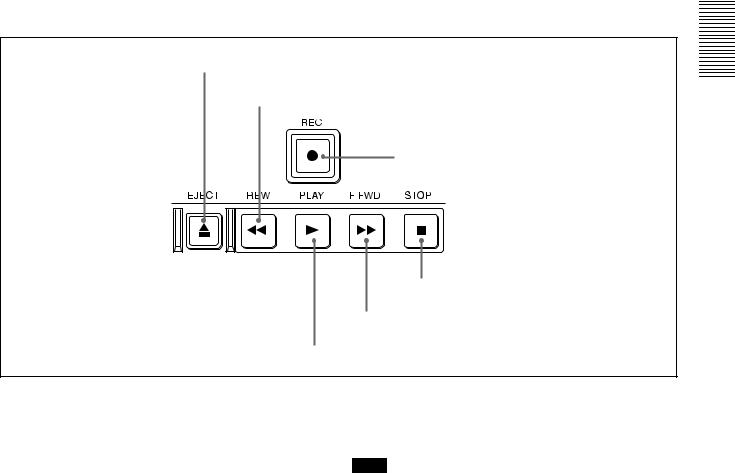
C Tape transport control section
a EJECT button
b REW button
c REC button |
f STOP button
e F FWD button
d PLAY button
a EJECT button
When you press this button, it lights and the cassette is automatically ejected after a few seconds.
b REW (rewind) button
When you press this button, it lights and the tape starts rewinding (maximum 85 times normal speed).
When the F. FWD/REW menu item (see page 63) is set to PB, you can monitor the playback picture during the rewind.
c REC (record) button
When you press the PLAY button while holding down this button, it lights and recording begins.
d PLAY button
When you press this button, it lights and playback begins. If you press this button during recording or editing, the recording or editing operation is stopped and this unit enters playback mode.
e F FWD (fast forward) button
When you press this button, it lights and the tape is fast forwarded (maximum 85 times normal speed).
When the F. FWD/REW menu item (see page 63) is set to PB, you can monitor the playback picture during the fast forward.
f STOP button
Press this button to stop the current tape transport operation.
Note
No tape transport control buttons other than the EJECT and STOP buttons will work while the REMOTE button in the remote control setting section is lit. This can be changed with the LOCAL ENABLE menu item (see page 63).
Overview 1 Chapter
Location and Function of Parts |
17 |
|
|
Overview 1 Chapter
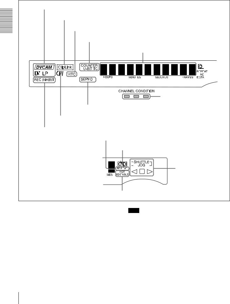
DDisplay section
a Recording/playback format indicators |
b ClipLink indicator |
c VITC indicator |
d Time data type indicators |
e Time counter display |
i CHANNEL CONDITION indicators |
h SERVO indicator |
g Cassette memory indicator |
f REC INHIBIT indicator |
j REPEAT indicator |
k Tape end alarm indicator |
l SHUTTLE/JOG indicators |
m NOT EDITABLE indicator |
a Recording/playback format indicators DVCAM: This lights when a tape recorded in DVCAM
format is played back.
DV: This lights when a tape recorded in consumer DV format is played back.
LP: This lights when a tape recorded in LP mode is played back.
When a tape recorded in DVCPRO (25M) format or any other format than those mentioned above is played back, none of the above indicators lights.
Note
A tape recorded in LP mode cannot be played back correctly. When a tape recorded in LP mode is played back, “DV LP” flashes and audio is muted.
b ClipLink indicator
Lights when a cassette is loaded on which ClipLink log data is stored in the cassette memory.
c VITC indicator
Lights when VITC is being read or recorded regardless of the data shown in the time counter display.
18 Location and Function of Parts
d Time data type indicators
One of the three indicators (COUNTER, U-BIT, and TC) lights to indicate the type of time data currently shown in the time counter display.
COUNTER: Count value of the time counter U-BIT: User bit data
TC: SMPTE time code (for DSR-1800A) or EBU time code (for DSR-1800AP)
e Time counter display
Indicates the count value of the time counter, time code, VITC, or user bit data depending on the settings of the COUNTER SEL button on the menu control panel and the TC SELECT menu item (see page 66).
Also used to display error messages and setup menu data.
f REC (recording) INHIBIT indicator
Lights in the following cases:
•The REC/SAVE switch on the loaded cassette is in the SAVE position.
•The REC INHIBIT menu item (see page 63) is set to ON.
g Cassette memory indicator
Lights when a cassette provided with a memory chip (“cassette memory”) is loaded.
h SERVO indicator
This indicator lights when the drum servo and capstan servo are locked*.
*Servo lock: This refers to the synchronization of the phase of the drum rotation and the reference signal for the tape transport position, so that the video heads can trace the same pattern on the tape for playback and recording.
i CHANNEL CONDITION indicators
These three-color indicators show the state of the playback signal.
Green: The state of the playback signal is good. Yellow: The playback signal is somewhat deteriorated, but
playback is possible.
Red: The playback signal is deteriorated. When the red indicator remains on, head cleaning or an internal inspection is necessary.
j REPEAT indicator
This indicator lights when the REPEAT MODE menu item
(see page 62) is set to ON.
k Tape end alarm indicator
Starts flashing when the remaining capacity of the tape is for about 2 minutes.
l SHUTTLE/JOG indicators
When searching in shuttle mode using the search dial, the SHUTTLE indicator lights, and when searching in jog mode using the search dial, the JOG indicator lights. When
the search dial is turned clockwise causing playback to take place in the forward direction, the G indicator lights. When the search dial is turned counterclockwise causing playback to take place in the reverse direction, the g indicator lights. When the tape is stopped, the s indicator lights.
For more information about the search dial, see “Search dial” in the next section.
m NOT EDITABLE indicator
Lights during playback of a tape that contains a recording in other than the DVCAM format. When this indicator is lit, the recordings contained in the tape can be used as source material for editing, but editing operations such as insert editing and assemble editing cannot be performed. This indicator also lights when the audio recording mode selected on this unit does not coincide with that of the loaded tape.
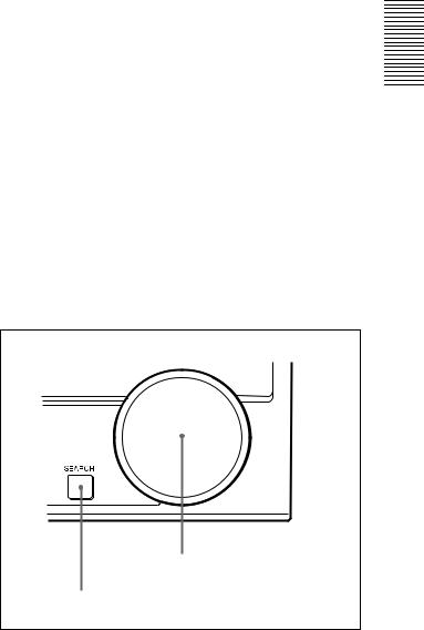
ESearch control section
b Search dial
a SEARCH button
a SEARCH button
To use the search dial for playback in shuttle or jog mode, press this button, turning it on. Pressing the dial toggles between shuttle and jog modes. In shuttle mode, the SHUTTLE indicator in the display section lights, and in jog mode, the JOG indicator in the display section lights.
b Search dial
Turn this to carry out playback in the modes shown in the following table. Turning the dial clockwise lights the G indicator in the display section and plays back in the forward direction. Turning the dial counterclockwise lights the g indicator in the display section and plays back in the reverse direction. When the tape is stopped, the s indicator in the display section lights.
Pressing this dial toggles playback between shuttle mode and jog mode. When playing back in shuttle mode, the
Overview 1 Chapter
Location and Function of Parts |
19 |
|
|
SHUTTLE indicator in the display section lights, and when playing back in jog mode, the JOG indicator lights. You can carry out noiseless playback in the range of ±1/2 times normal speed.
Playback modes using the search dial
|
|
Playback mode |
Operation and functions |
|
|
||
|
|||
|
|||
|
|
|
|
|
|
Shuttle |
Press the SEARCH button or the search |
|
|||
|
|||
|
|||
|
|
|
dial so that the SHUTTLE indicator in |
Chapter |
|
||
|
the display section lights, then turn the |
||
|
|
|
|
|
|
|
search dial. |
1 |
|
|
Playback is carried out at a speed |
|
|
determined by the position of the search |
|
Overview |
|
||
|
SHUTTLE menu item (see page 63). |
||
|
|
|
dial. The maximum shuttle mode |
|
|
|
playback speed can be changed with the |
|
|
|
|
|
|
Jog |
Press the SEARCH button or the search |
|
|
|
dial so that the JOG indicator in the |
|
|
|
display section lights, then turn the |
|
|
|
search dial. Playback is carried out at a |
|
|
|
speed determined by the speed of |
|
|
|
rotation of the search dial. The playback |
|
|
|
speed is up to ±1 times normal speed by |
|
|
|
factory default. |
|
|
|
The search dial has no detents. |
|
|
|
|
You can use the SEARCH ENABLE menu item (see page 63) to select either of the following as the operation to be performed to put the unit into search mode (shuttle or jog).
•Either press the SEARCH button or, except during recording/editing, turn the search dial (factory default setting).
•Press the SEARCH button.
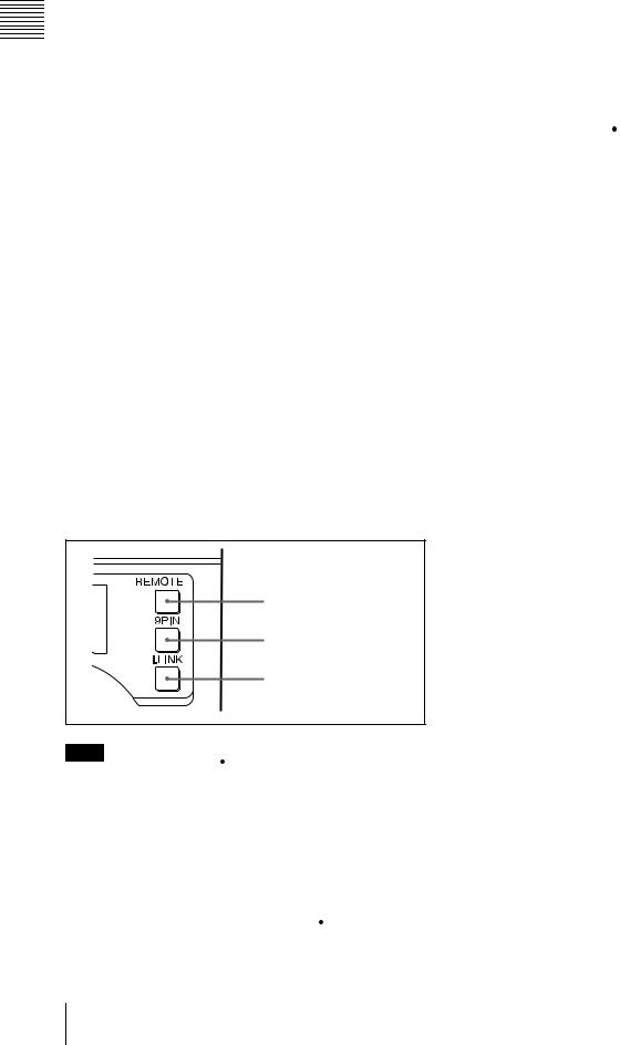
FRemote control setting section
a REMOTE button
b 9PIN button
c i.LINK button
When reverting to local mode to use the buttons in the tape transport control section, press this button again, turning it off.
b 9PIN button
When carrying out remote control between this unit and the unit connected to the REMOTE connector, press this button, turning it on.
c i.LINK button
When carrying out remote control between this unit and the unit connected to the  DV IN/OUT connector, press this button, turning it on.
Note
When you edit using the DV IN/OUT connector, with video and audio signal input set to “i.LINK” and remote control set to “9PIN”, the locations where edit points are actually set may not be the same as the specified locations. When you set video and audio signal input to “i.LINK”, set remote control to “i.LINK” as well.
a REMOTE button
When remote-controlling this unit from the unit connected to the REMOTE connector (page 25) or  DV IN/OUT connector (page 23), press this button, turning it on.
20 Location and Function of Parts
Rear Panel
AAnalog video signal input/output section (see page 22)
BDigital signal input/output section (see page 23)
|
|
DV IN/OUT |
|
|
|
|
|
|
|
SDI |
|
|
DIGITAL AUDIO(AES/EBU) |
|||
|
|
|
|
|
|
|
|
|
|
IN |
|
OUT |
|
|
IN CH-1/2 |
CH-3/4 OUT CH-1/2 CH-3/4 |
ANALOG VIDEO |
|
|
|
|
|
|
|
|
|
|
|
|
|
|
TIME CODE |
|
VIDEO IN |
|
S VIDEO |
COMPONENT VIDEO IN |
REF.VIDEO |
VIDEO OUT |
S VIDEO COMPONENT VIDEO OUT |
|
|||||||||
|
|
IN |
|
Y |
R-Y |
B-Y |
IN |
OUT |
1 |
2 |
OUT |
Y |
R-Y |
B-Y |
IN |
OUT |
|
|
|
|
|
|
|
|
|
|
(SUPER) |
|
|
|
|
|
VIDEO CONTROL |
|
|
|
|
|
|
|
|
|
|
|
|
|
|
|
|
|
AUDIO IN LOW LEVEL |
HIGH |
LOW LEVEL |
HIGH |
LOW LEVEL HIGH |
LOW LEVEL |
HIGH |
AUDIO OUT |
|
|
|
|
|
MONITOR OUT |
|||
OFF |
ON |
OFF |
ON |
OFF |
ON |
OFF |
ON |
|
|
|
|
|
|
|
|
|
|
600Ω |
600Ω |
|
600Ω |
|
600Ω |
|
|
|
|
|
|
|
|
|
|
|
|
|
|
|
|
|
|
|
|
|
|
|
|
|
AUDIO |
|
|
|
|
|
|
|
|
|
|
|
|
|
|
|
|
|
REMOTE |
CH-1 |
CH-2 |
CH-3 |
CH-4 |
|
CH-1 |
|
CH-2 |
CH-3 |
CH-4 |
|
|
|
~AC IN |
|||
|
|
|
|
|
|
|
|
|
|
|
|
|
|
|
|
|
DExternal device connectors (see page 25) |
AC IN connector |
CAnalog audio signal input/output section (see page 24)
AC IN connector
Use the supplied power cord to connect this to an AC outlet.
Overview 1 Chapter
Location and Function of Parts |
21 |
|
|
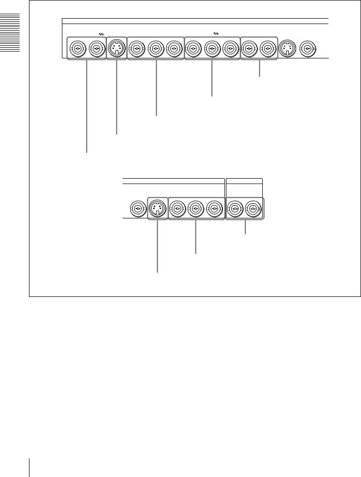
AAnalog video signal input/output section
Overview 1 Chapter
ANALOG VIDEO |
|
|
|
|
|
|
|
|
|
|
|
|
|
|
COMPONENT VIDEO IN |
|
|
|
REF.VIDEO |
|
|
|
|
|
|
|
|
|
|
|
|
S VIDEO |
|
|
|
||||||||||||||||||||||||||||||||||
|
|
VIDEO IN |
|
|
S VIDEO |
|
|
|
|
|
|
|
|
|
|
VIDEO OUT |
|
|
|
||||||||||||||||||||||||||||||||||||||||||||||||||
|
|
|
|
|
|
|
|
|
|
|
|
|
|
IN |
|
|
Y |
|
|
|
R-Y |
|
|
|
B-Y |
|
|
|
|
|
IN |
OUT |
|
1 |
2 |
|
|
|
OUT |
|
|
Y |
|||||||||||||||||||||||||||
|
|
|
|
|
|
|
|
|
|
|
|
|
|
|
|
|
|
|
|
|
|
|
|
|
|
|
|
|
|
|
|
|
|
|
|
|
|
|
|
|
|
|
|
|
|
|
|
|
|
|
|
|
|
(SUPER) |
|
|
|
|
|
|
|
|
|
|
|
|
|||
|
|
|
|
|
|
|
|
|
|
|
|
|
|
|
|
|
|
|
|
|
|
|
|
|
|
|
|
|
|
|
|
|
|
|
|
|
|
|
|
|
|
|
|
|
|
|
|
|
|
|
|
|
|
|
|
|
|
|
|
|
|
|
|
|
|
|
|
|
|
|
|
|
|
|
|
|
|
|
|
|
|
|
|
|
|
|
|
|
|
|
|
|
|
|
|
|
|
|
|
|
|
|
|
|
|
|
|
|
|
|
|
|
|
|
|
|
|
|
|
|
|
|
|
|
|
|
|
|
|
|
|
|
|
|
|
|
|
|
|
|
|
|
|
|
|
|
|
|
|
|
|
|
|
|
|
|
|
|
|
|
|
|
|
|
|
|
|
|
|
|
|
|
|
|
|
|
|
|
|
|
|
|
|
|
|
|
|
|
|
|
|
|
|
|
|
|
|
|
|
|
|
|
|
|
|
|
|
|
|
e VIDEO OUT 1 and 2 (SUPER)
connectors
d REF. VIDEO IN/OUT connectors
c COMPONENT VIDEO IN Y/R−Y/B−Y connectors
b S VIDEO IN connector
a VIDEO IN connectors
|
|
|
|
|
|
|
|
|
|
|
|
|
|
|
|
|
|
|
|
|
|
|
|
|
|
|
|
TIME CODE |
||||
VIDEO OUT |
S VIDEO |
COMPONENT VIDEO OUT |
|
|
|
|
|
|
||||||||||||||||||||||||
2 |
|
|
|
OUT |
|
|
|
|
Y |
|
R-Y |
|
|
|
B-Y |
|
IN |
|
|
|
OUT |
|||||||||||
|
|
|
|
|
|
|
|
|
|
|
|
|
|
|
|
|
|
|
|
|
|
|
|
|
|
|
|
|
|
|
|
|
|
|
|
|
|
|
|
|
|
|
|
|
|
|
|
|
|
|
|
|
|
|
|
|
|
|
|
|
|
|
|
|
|
|
|
|
|
|
|
|
|
|
|
|
|
|
|
|
|
|
|
|
|
|
|
|
|
|
|
|
|
|
|
|
|
|
h TIME CODE IN/OUT connectors
g COMPONENT VIDEO OUT Y/R−Y/B−Y connectors
f S VIDEO OUT connector
a VIDEO IN connectors (BNC type)
Input an analog composite video signal. This connector block has a built-in automatic 75 Ω termination switch. When a signal is input to the left VIDEO IN connector with no bridging (loop-through) connection made, the connector is terminated with an impedance of 75 Ω automatically. To connect the signal input to the left VIDEO IN connector also to other equipment, use the right VIDEO IN connector (marked  ). When the right VIDEO IN connector is used, the built-in 75 Ω termination switch turns off automatically.
b S VIDEO IN connector (4-pin)
Input an S-video signal with separated Y (luminance) and C (chroma: 3.58 MHz for DSR-1800A or 4.43 MHz for DSR-1800AP) components to this connector.
cCOMPONENT VIDEO IN Y/R−Y/B−Y connectors
(BNC type)
Input analog component video signals (Y/R−Y/B−Y) to these connectors.
dREF. (reference) VIDEO IN/OUT connectors (BNC type)
Input a reference video signal. The IN connector block has a built-in automatic 75 Ω termination switch. When a signal is input to the left REF. VIDEO IN connector with no bridging (loop-through) connection made, the connector is terminated with an impedance of 75 Ω automatically. To connect the reference video signal input to the left REF. VIDEO IN connector also to other equipment, use the right REF. VIDEO IN connector (marked  ). When the right REF. VIDEO IN connector
22 Location and Function of Parts
is used, the built-in 75 Ω termination switch turns off automatically.
The REF. VIDEO OUT connector outputs a reference video signal, except when i.LINK is selected in the INPUT SELECT section (see page 16).
eVIDEO OUT 1 and 2 (SUPER) connectors (BNC type)
These connectors output analog composite video signals. When the CHARA. DISPLAY menu item (see page 65) is set to ON (factory default setting), connector 2 (SUPER) outputs a signal with superimposed text information.
f S VIDEO OUT connector (4-pin)
This connector outputs an S-video signal with separated Y (luminance) and C (chroma: 3.58 MHz for DSR-1800A or 4.43 MHz for DSR-1800AP) components.
g COMPONENT VIDEO OUT Y/R−Y/B−Y connectors (BNC type)
These connectors output analog component video signals (Y/R−Y/B−Y).
h TIME CODE IN/OUT connectors (BNC type)
Input SMPTE time code (for DSR-1800A) or EBU time code (for DSR-1800AP) externally generated to the IN connector.
The OUT connector outputs a time code according to the operating state of the unit, as follows:
During playback: the playback time code
During recording: the time code generated by the internal time code generator or the time code input to the TIME CODE IN connector. When the EE OUT PHASE menu item (see page 67) is set to MUTE, no time code is output.
BDigital signal input/output section (optional DSBK-1801 board required)
 DV IN/OUT
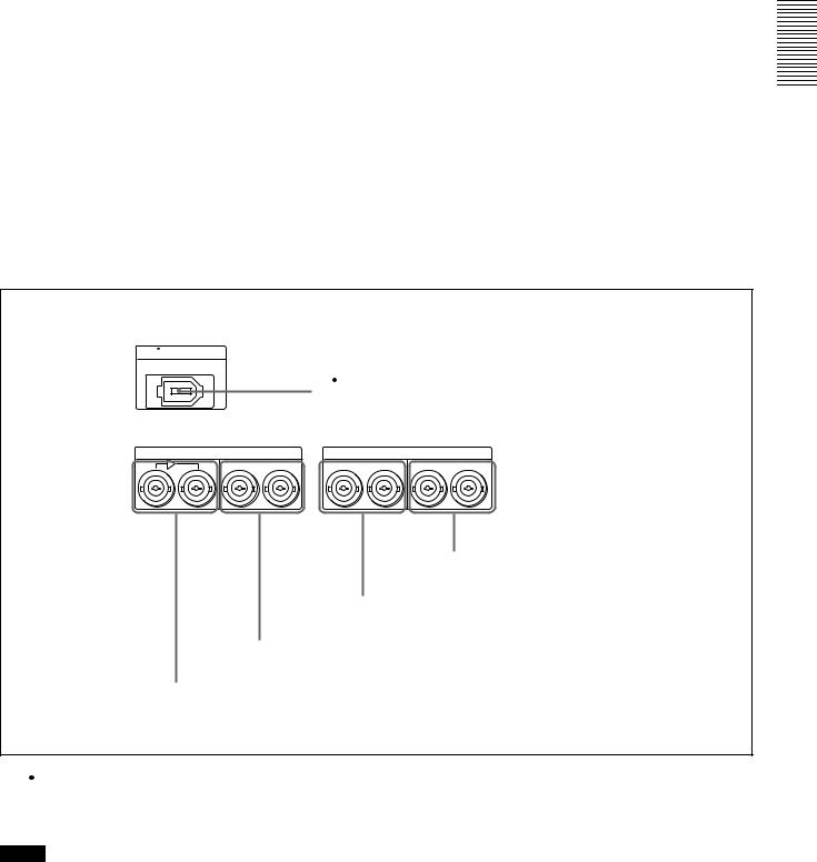
a  DV IN/OUT connector
|
SDI |
DIGITAL AUDIO(AES/EBU) |
IN |
OUT |
IN CH-1/2 CH-3/4 OUT CH-1/2 CH-3/4 |
Overview 1 Chapter
5 DIGITAL AUDIO (AES/EBU) OUT connectors
4 DIGITAL AUDIO (AES/EBU) IN connectors
3 SDI OUT connectors
2 SDI IN and active through output connectors
a  DV IN/OUT connector (6-pin IEEE-1394)
This i.LINK-compatible connector inputs and outputs digital video and audio signals in DV format.
Notes
•When searching at speeds in the range +1/2 to +1/30 or −1/2 to −1/30 times normal speed, the audio signal output
from this connector and monitored on external equipment may sound differently from the audio signal played back on this unit.
•When you connect this unit to another device with a 6- pin DV connector, always power the other device off and unplug its power cord from the power output before connecting or disconnecting the i.LINK cable (DV cable). If you connect or disconnect the cable with the power cord still plugged in, power from the DV connector may flow into this unit, possibly damaging this unit.
•When you connect this unit to another device with a 6- pin DV connector, make the connection to the 6-pin DV
Location and Function of Parts |
23 |
|
|
Overview 1 Chapter
connector on the other device before making the connection to this unit.
bSDI (Serial Digital Interface) IN (input) and active through output connectors (BNC type) (optional
DSBK-1801 SDI/AES/EBU Input/Output Board required)
Input digital video and audio signals in SDI format to the left-hand connector. The right-hand connector is for an active-through connection.
cSDI (Serial Digital Interface) OUT connectors (BNC type) (optional DSBK-1801 SDI/AES/EBU Input/Output Board required)
Output SDI-format digital video and audio signals. The same signals are output from both connectors.
CAnalog audio signal input/output section
d DIGITAL AUDIO (AES/EBU) IN connectors
(BNC type) (optional DSBK-1801 SDI/AES/EBU Input/Output Board required)
Input digital audio signals in AES/EBU format to these connectors.
The left-hand connector (CH-1/2) is for audio channels 1 and 2, and the right-hand connector (CH-3/4) is for audio channels 3 and 4.
e DIGITAL AUDIO (AES/EBU) OUT connectors
(BNC type) (optional DSBK-1801 SDI/AES/EBU Input/Output Board required)
These connectors output digital audio signals in AES/EBU format.
The left-hand connector (CH-1/2) is for audio channels 1 and 2, and the right-hand connector (CH-3/4) is for audio channels 3 and 4.
|
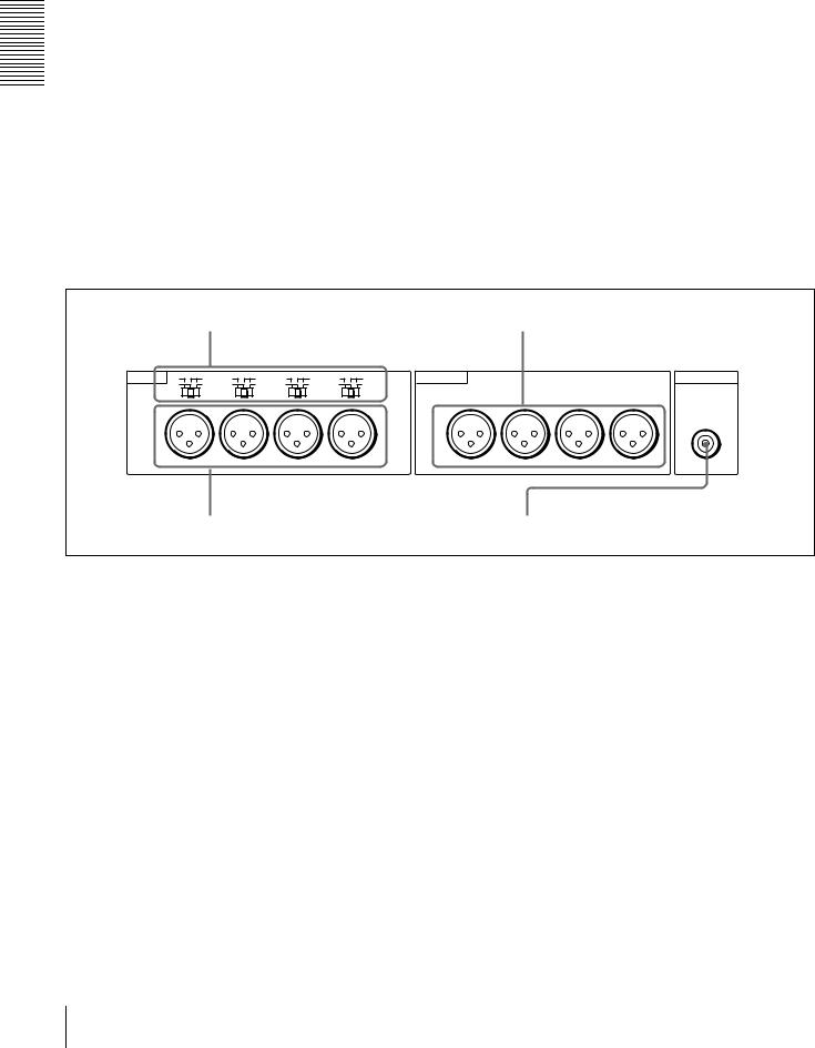
a AUDIO IN LEVEL/600 Ω switches |
|
|
c AUDIO OUT CH-1 to CH-4 connectors |
|||||||
AUDIO IN LOW LEVEL |
HIGH |
LOW LEVEL |
HIGH |
LOW LEVEL |
HIGH |
LOW LEVEL |
HIGH |
AUDIO OUT |
|
|
MONITOR OUT |
OFF |
ON |
OFF |
ON |
OFF |
ON |
OFF |
ON |
|
|
|
|
|
600Ω |
|
600Ω |
|
600Ω |
|
600Ω |
|
|
|
|
|
|
|
|
|
|
|
|
|
|
|
AUDIO |
CH-1 |
CH-2 |
CH-3 |
CH-4 |
|
CH-1 |
CH-2 |
CH-3 |
CH-4 |
|||
|
b AUDIO IN CH-1 to CH-4 connectors |
|
|
d AUDIO MONITOR OUT connector |
|||||||
a AUDIO IN LEVEL/600 Ω switches
Set these switches for each channel as shown in the following table, according to the audio input levels to the AUDIO IN CH-1 to CH-4 connectors and the required impedance.
Settings of the AUDIO IN LEVEL/600 Ω switches
Audio input |
|
Switch setting |
|
|
|
Level |
Impedance |
|
|
|
|
−60 dBu |
High impedance |
LOW-OFF |
(microphone input) |
(about 20 kΩ) |
(left position) |
|
|
|
+4/0/−3 a)/−6 dBu |
High impedance |
HIGH-OFF |
(line audio input) |
(about 20 kΩ) |
(middle |
|
|
position) |
|
|
|
+4/0/−3 a)/−6 dBm |
600 Ω |
HIGH-ON |
(line audio input) |
|
(right position) |
|
|
|
a) Selectable on DSR-1800AP only
b AUDIO IN CH-1 (channel 1) to CH-4 connectors
(XLR 3-pin, female)
Use these connectors to connect separate channels of analog audio input from a player VCR or other external audio equipment.
You can switch the audio input level setting with the LEVEL SELECT menu item (see page 71).
c AUDIO OUT CH-1 (channel 1) to CH-4 connectors
(XLR 3-pin, male)
These connectors output channel-1 to channel-4 analog audio signals, respectively.
It is possible to use the AUDIO OUT CH-3 and AUDIO OUT CH-4 connectors for audio monitor output for channels 1 and 2, respectively (use the OUTPUT CH3/4 menu item (see page 71)).
d AUDIO MONITOR OUT connector (RCA phono jack)
This connector outputs audio signals for monitoring. The audio signals to be output from this connector can be
24 Location and Function of Parts
selected with the MONITOR SELECT switches on the menu control panel.
D External device connectors
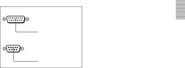
VIDEO CONTROL
a VIDEO CONTROL connector
REMOTE
b REMOTE connector
a VIDEO CONTROL connector (D-sub 15-pin)
For remote control of the internal digital video processor, connect an optional remote control unit to this connector.
b REMOTE connector (D-sub 9-pin)
Use the optional 9-pin remote cable to connect an editing controller that supports this unit, or a VCR that supports editing with two units (DSR-2000A/2000AP, etc.), to connect those devices to this unit for remote control.
Overview 1 Chapter
Location and Function of Parts |
25 |
|
|

Overview 1 Chapter
26 Location and Function of Parts

Recording and Playback Chapter 2
Usable Cassettes
This unit can use the DVCAM cassettes listed below.
Model name |
Size |
|
|
PDV-34*/64*/94*/124*/184* |
Standard size |
|
|
PDVM-12*/22*/32*/40* |
Mini size |
|
|
The * in each model name is actually “ME” (indicating that a cassette memory is contained), or “N” (indicating that no cassette memory is contained).
The numbers in each model name indicate the maximum recording/playback time (in minutes) for each model. For example, the PDV-184ME has a maximum recording/playback time of 184 minutes.
Cassettes usable for playback only
Largeand medium-size DVCPRO (25M) cassettes are usable for playback only.
Notes
•If you insert an incorrect type of cassette, it will be automatically ejected.
•Although this unit can use DV series consumer cassettes, video or audio noise may occur on some tapes.
For reliable playback, editing, recording, and storage, use DVCAM cassettes.
•Cassettes that have been recorded by a DV-format recorder can be played back on this unit but cannot be used for recording at editing operation. When you insert such a cassette into this unit, the NOT EDITABLE indicator lights up in the display section on the front panel of this unit.
•See the note in page 18.
Usable Cassettes 27

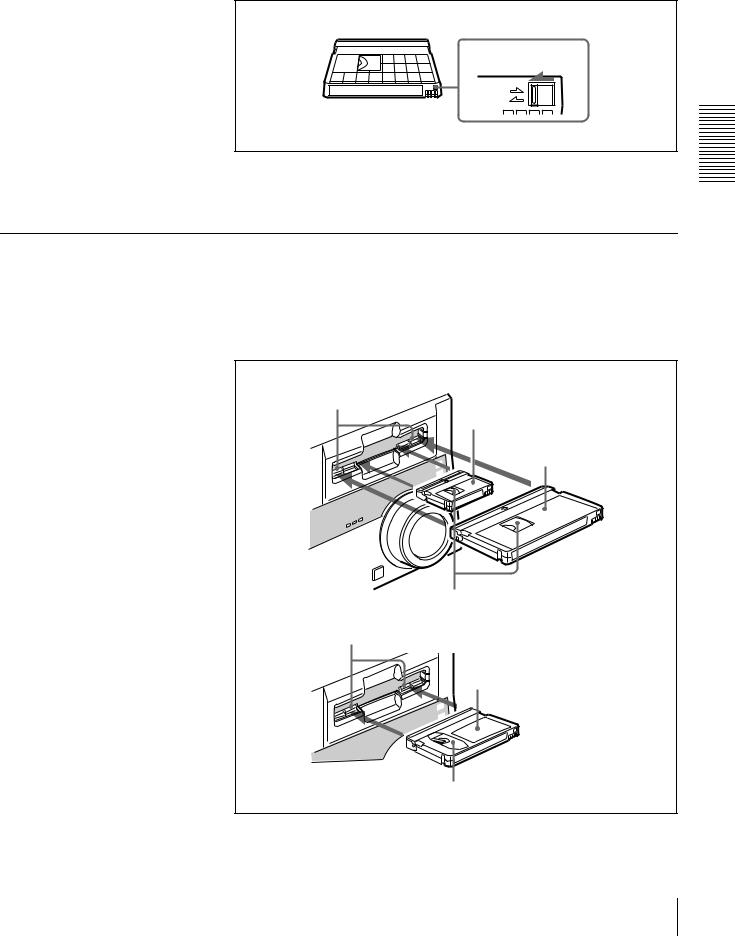
DVCAM cassettes
The following figure illustrates the DVCAM cassettes.
Playback and Recording 2 Chapter
REC/SAVE switch
For details of this switch, see “Preventing accidental erasure” on page 29
Mini size |
Standard size |
Cassette memory
Notes on using cassettes
•Before storing the cassette for a long period of time, rewind the tape to the beginning and be sure to put the cassette in its storage case, preferably on end instead of flat on its side.
Storing a cassette in any other condition (not rewound, out of its case, etc.) may cause the video and audio contents to become damaged over time.
•If the cassette memory connector (contact point) becomes dirty, connection problems may occur, causing a loss of functions. Remove away any dust or dirt from this area before using the cassette.
•If the cassette is dropped on the floor or otherwise receives a hard impact, the tape may become slackened and may not record and/or play back correctly.
For information about how to check the tape for slack, see the next section.
Checking the tape for slack
Using a paper clip or a similar object, turn the reel gently in the direction shown by the arrow. If the reel does not move, there is no slack. Insert the cassette into the cassette compartment, and after about 10 seconds take it out.
Paper clip, etc.
Reel
28 Usable Cassettes
Preventing accidental erasure
Set the REC/SAVE switch on the cassette to SAVE to prevent accidental erasure of recorded contents.
REC/SAVE switch
Set to SAVE
REC
SAVE
To enable re-recording
Set the REC/SAVE switch to REC.
When this switch is set to SAVE, the unit cannot record on the tape.
Inserting and Ejecting Cassettes
Inserting a cassette
This unit accepts three sizes of cassette: L (standard size), M (medium size: DVCPRO) and S (mini size). When inserting a cassette in the unit, make sure its tape window faces upward as shown in the following figure.
Outer guides
Mini size (Insert the cassette into the middle of the cassette compartment.)
Standard size
Tape window facing upward
Inner guides
Medium size (Align the cassette with the outer guides, then slide it in over the inner guides.)
Tape window facing upward
Playback and Recording 2 Chapter
Usable Cassettes 29
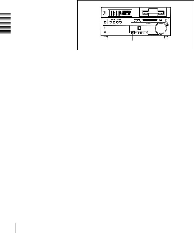
No double insertion of cassettes
When you insert a cassette, the orange lock-out plate appears in the cassette compartment to prevent double insertion.
Ejecting a cassette
Press the EJECT button.
Playback and Recording 2 Chapter
|
|
|
|
INPUT |
V:SDTI |
|
SDTI |
i.LINK |
|
|
|
|
|
VIDEO |
COMPOSITE |
Y-R,B S VIDEO |
SDI |
SG |
|
|
|
|
|
CH11/2 |
ANALOG |
AES/EBU |
SDI |
SG |
|
|
|
|
|
AUDIO |
ANALOG |
AES/EBU |
SDI |
SG |
|
|
|
|
|
CH23/4 |
|||||
1 |
2 |
3 |
4 |
PB FS |
48k44.1k32k |
REC MODE |
2CH4CH |
||
EJECT button
30 Usable Cassettes
 Loading...