


DSR-1600
Digital
Videocassette
Player
3-204-677-12(1)
Operating Instructions
Before operating the unit, please read this manual
thoroughly and retain it for future reference.
DSR-1600/1600P
© 2000 Sony Corporation
Owner’s Record
The model and serial numbers are located at the rear.
Record these numbers in the spaces provided below. Refer
to them whenever you call upon your Sony dealer
regarding this product.
WARNING: THIS WARNING IS APPLICABLE FOR
USA ONLY.
Using this unit at a voltage other than 120 V may require
the use of a different line cord or attachment plug, or both.
To reduce the risk of fire or electric shock, refer servicing
to qualified service personnel.
Model No.
Serial No.
WARNING
To prevent fire or shock hazard, do not
expose the unit to rain or moisture.
To avoid electrical shock, do not open the
cabinet. Refer servicing to qualified
personnel only.
THIS APPARATUS MUST BE EARTHED.
For customers in the USA
This equipment has been tested and found to comply with
the limits for a Class A digital device, pursuant to Part 15
of the FCC Rules. These limits are designed to provide
reasonable protection against harmful interference when
the equipment is operated in a commercial environment.
This equipment generates, uses, and can radiate radio
frequency energy and, if not installed and used in
accordance with the instruction manual, may cause
harmful interference to radio communications. Operation
of this equipment in a residential area is likely to cause
harmful interference in which case the user will be
required to correct the interference at his own expense.
You are cautioned that any changes or modifications not
expressly approved in this manual could void your
authority to operate this equipment.
The shielded interface cable recommended in this manual
must be used with this equipment in order to comply with
the limits for a digital device pursuant to Subpart B of Part
15 of FCC Rules.
This symbol is intended to alert the user to
the presence of uninsulated “dangerous
voltage” within the product’s enclosure
that may be of sufficient magnitude to
constitute a risk of electric shock to
persons.
This symbol is intended to alert the user to
the presence of important operating and
maintenance (servicing) instructions in
the literature accompanying the
appliance.
For customers in Europe (DSR-1600P only)
This product with the CE marking complies with both the
EMC Directive (89/336/EEC) and the Low Voltage
Directive (73/23/EEC) issued by the Commission of the
European Community.
Compliance with these directives implies conformity to
the following European standards:
• EN60065: Product Safety
• EN55103-1: Electromagnetic Interference (Emission)
• EN55103-2: Electromagnetic Susceptibility (Immunity)
This product is intended for use in the following
Electromagnetic Environment(s):
E1 (residential), E2 (commercial and light industrial), E3
(urban outdoors) and E4 (controlled EMC environment,
ex. TV studio).
2

Table of Contents
Chapter 1 Overview
Chapter 2 Playback
Features........................................................................5
DVCAM Format .............................................................5
A Wealth of Interfaces .................................................... 6
Facilities for High-Efficiency Editing.............................6
Other Features.................................................................7
Optional Accessories....................................................... 7
Location and Function of Parts..................................8
Front Panel ...................................................................... 8
Rear Panel .....................................................................14
Playback.....................................................................19
Usable Cassettes............................................................ 19
Inserting and Ejecting Cassettes ...................................21
Settings for Playback ....................................................22
Playback Procedure....................................................... 23
Repeat Playback—Automatic Cyclical Playback .........25
Setting Points A and B for Repeat Playback................. 25
Cuing Up to Any Desired Position Set as Point
A or B ..................................................................30
Chapter 3 Convenient Functions for Editing Operation
Displaying Time Data and Other Text
Information..........................................................31
Displaying Time Data and Operation Mode
Indications ...........................................................31
High-Speed and Low-Speed Search—Quickly
and Accurately Determining Editing Points.....34
Search Operations via External Equipment ..................34
Search Operations on This Unit....................................34
Chapter 4 Menu Settings
Menu Organization ....................................................37
Menu Contents...........................................................40
Setup Menu ................................................................... 40
Changing Menu Settings ..........................................47
Buttons Used to Change Settings..................................47
Table of Contents
3

Changing the Settings of Basic Items ........................... 47
Displaying Enhanced Items ..........................................49
Changing the Settings of Enhanced Items ....................49
Returning Menu Settings to Their Factory Default
Settings ................................................................50
Chapter 5 Connections and Settings
Connections for a Digital Non-Linear Editing
System.................................................................51
Connections for a Cut Editing System....................53
Connections for an A/B Roll Editing System..........54
Adjusting the Sync and Subcarrier Phases............60
Chapter 6 Maintenance and Troubleshooting
Maintenance...............................................................63
Condensation................................................................. 63
Regular Checks ............................................................. 63
Head Cleaning............................................................... 65
Troubleshooting ........................................................66
Error Messages.............................................................. 67
Alarm Messages............................................................ 67
Appendixes
Precautions................................................................69
Specifications ............................................................70
ClipLink Guide ...........................................................73
What Is ClipLink?......................................................... 73
Example System Configuration and Operation Flow ... 74
Data Generated When Shooting....................................75
Glossary .....................................................................78
Index ...........................................................................81
Table of Contents
4

Overview
Features
The DSR-1600/1600P is a 1/4-inch digital video cassette
player using the DVCAM digital recording format. It
achieves stable, superb picture quality by digitally
processing video signals separated into color difference
signals and luminance signals (component method).
The unit is equipped with a variety of functions needed for
videocassette players used in professional digital video
editing systems. It supports the ClipLink
developed by Sony Corporation for highly efficient video
editing. When connected to a Sony EditStation
serves as part of a powerful non-linear editing system*.
The unit is also equipped with a full-fledged analog
interface to support hybrid systems that combine
conventional analog equipment with digital equipment.
* Non-linear editing: This is an editing method that uses video and audio
signals digitally encoded and recorded on a hard disk as digital data. When
compared with conventional (linear) editing methods, non-linear editing
offers vastly improved efficiency in editing operations, for example, by
eliminating tape transport time.
The main features of the unit are described in the
following.
DVCAM Format
DVCAM is based on the consumer DV format, which uses
the 4:1:1 component digital format, and provides a
digital recording format for professional use.
High picture quality, high stability
Video signals are separated into color difference signals
and luminance signals, which are encoded and compressed
to one-fifth size before being recorded to ensure stable and
superb picture quality.
TM
function
TM
, the unit
1
/4-inch
Chapter
Because the recording is digital, multi-generation dubbing
can be performed with virtually no deterioration of quality.
Wide track pitch
The recording track pitch is 15 µm, fully 50 percent wider
than the 10-µm track pitch of the DV format. Thanks to this
feature, the DVCAM format sufficiently meets the
reliability and precision requirements of professional
editing.
High-quality PCM digital audio
PCM recording makes for a wide dynamic range and a
high signal-to-noise ratio, thereby enhancing sound
quality.
There are two recording modes: 2-channel mode (48-kHz
sampling and 16-bit quantization), which offers sound
quality equivalent to the DAT (Digital Audio Tape)
format, or 4-channel mode (32-kHz sampling and 12-bit
quantization). Cassettes recorded in either mode can be
played back on this unit.
Playback compatibility with DV and
DVCPRO formats
A DV cassette recorded on a DV format VCR as well as a
DVCPRO (25M) format recorded cassette can be played
back on this unit.
Note
When playing back a tape recorded in DVCPRO (25M)
format, the SDTI and i.LINK outputs (see “Digital
interfaces” on page 6) of this unit are muted. Furthermore,
it is not possible to playback the cue-audio track of the
tape.
1
Features
5

Support for three cassette sizes
There are two sizes of DVCAM cassette: standard and
mini. You can use either size with this unit.
The unit also accepts L and M sizes of DVCPRO cassette.
• When a cassette is inserted, the reel mechanism of the
unit automatically adjusts to the size of the inserted
cassette.
• The capacity of a standard cassette is 184 minutes of
Chapter 1 Overview
playback, and that of a mini cassette is 40 minutes.
A Wealth of Interfaces
Facilities for High-Efficiency Editing
The unit provides an abundance of functions that enhance
editing efficiency and precision.
Support for ClipLink function
In response to commands sent from the EditStation, index
pictures recorded on tape or ClipLink log data recorded in
the cassette memory can be transferred to the EditStation.
The EditStation operator can then efficiently use these
pictures and data in a preliminary editing session.
Digital interfaces
The following optional digital interfaces are available for
use with the unit.
SDTI (QSDI)* (optional DSBK-1602 SDTI (QSDI)
Output Board): When the unit is fitted with the
optional DSBK-1602 board, it can transfer
compressed SDTI (QSDI)-format video, audio and
time code signals to the Sony EditStation at normal
speed.
SDI (serial digital interface)/AES/EBU (optional
DSBK-1601 SDI/AES/EBU Output Board): When
the unit is fitted with the optional DSBK-1601 board,
it can output D1 (component)-format digital video and
audio signals and also AES/EBU-format digital audio
signals.
i.LINK (DV)** (optional DSBK-1803 i.LINK/DV
Input/Output Board): The optional DSBK-1803
board (i.LINK compatible) enables input/output of
digital video and audio signals in DV format (output
only when installed in the DSR-1600/1600P).
* SDTI is the name of a standard interface established as SMPTE 305M.
QSDI is a type of SDTI. This unit uses SDTI to transmit DV data, and the
input/output connectors are labeled “SDTI (QSDI).”
** i.LINK and are trademarks and indicate that this product is in agreement
with IEEE1394-1995 specifications and their revisions.
Analog interfaces
The unit also comes with analog interfaces enabling it to be
connected to analog video and audio equipment.
Analog video: Output connectors for component,
composite, and S-video signals are provided.
Analog audio: Four output channels are provided.
For an overview of the ClipLink function, see the appendix
“ClipLink Guide” (page 73).
Internal time code reader
An internal time code reader enables time code compliant
with SMPTE (for DSR-1600)/EBU (DSR-1600P) format
to be played back. This allows editing to single frame
precision.
Outputting time code (LTC) to an external device is also
possible using the TIME CODE OUT connector.
The unit is also compatible with VITC.
Remote control
The unit can be operated by remote control from an editing
control unit that supports the RS-422A interface or from an
optional SIRCS*-compatible remote control unit such as
the DSRM-10.
* SIRCS (Sony Integrated Remote Control System): A command protocol
to remote control Sony professional videocassette recorders/players.
Playback control using search dial
The search dial on the front panel of the unit allows you to
carry out playback operation in jog or shuttle mode
without requiring an external editing control unit or remote
control unit to be connected to the unit.
High-speed search function
The unit has a picture search function that allows you to
view color picture at playback speeds up to 85 times
normal speed in forward and reverse directions.
When remote-controlling this unit in shuttle mode from an
editing control unit or a remote control unit, you can search
at any speed in the range 0 (still) to 60 times normal speed
in both directions. You can also search frame-by-frame in
jog mode.
At search speeds up to 10 times normal speed in both
directions, you can also hear playback audio.
6
Features

Digital slow-motion playback
Using the frame memory function, the unit can show
noise-free slow-motion playback at speeds ranging from 0
1
to
/2 times normal speed in both directions.
Digital jog sound function
When searching at speeds in the range +1 to +1/30* or
1
−
/30 to −1 times normal speed, the digital jog sound
function is enabled. The audio signal is saved in temporary
memory, and replayed according to the search speed. This
allows searching on the sound track.
* The positive direction refers to forward movement of the tape, and the
negative direction to reverse movement.
Digital hours meter: The digital hours meter functions
include four kinds of tally operations for operating
hours, head drum usage hours, tape transport hours,
and tape threading/unthreading times. The tally results
can be viewed on the video monitor or the time counter
display.
Compatible with wide-screen aspect ratio
(16:9)
The unit can play back aspect ratio information. When
video accompanied by wide-screen aspect ratio
information is played back, the unit can output the video
signal also containing the aspect ratio information.
Chapter 1 Overview
Video process control
For analog video output and SDI-format video output, you
can adjust the video output level, chroma signal output
level, setup level (for DSR-1600), black level (for DSR1600P), and chroma phase.
Other Features
Function to make a convenient
presentation tool of this unit
“Repeat playback” function
The unit can perform automatic cyclical playback between
two selected points on the tape.
“Power-on playback” function (in repeat
playback mode)
You can choose a menu setting so that powering on the
unit makes it immediately start playback.
Menu system for functionality and
operation settings
The unit provides a menu system to make its various
functions easier to use and set up its operation conditions.
Rack mountable
When you use the optional RMM-130 Rack Mount Kit,
you can mount this unit onto an EIA-standard 19-inch rack
(height = 4 units).
Optional Accessories
DSBK-1601 SDI/AES/EBU Output Board
When installed in the unit, this optional board enables
digital video and audio signals in the D1 format and also
AES/EBU-format digital audio signals to be output from
the unit to digital Betacam VCRs or other equipment.
DSBK-1602 SDTI (QSDI) Output Board
This interface allows the unit to transfer video, audio and
time code signals in SDTI (QSDI) format to the Sony
EditStation at normal speed. When this unit is connected to
another DVCAM VCR, it is possible to transfer
compressed signals from this unit to the connected VCR.
DSBK-1803 i.LINK/DV Input/Output Board
This board allows you to connect the unit to other
equipment provided with a Sony DV connector to carry
out editing or dubbing of digital video and audio signals.
Superimposition function
Time code values, operation mode indications, error
messages, and other text data can be superimposed and
output in analog composite video signals.
Easy maintenance functions
Self-diagnostic/alarm function: This function
automatically detects setup and connection errors,
operation faults, and other problems. It also displays a
description of the problem, its cause, and the
recommended response on the video monitor screen or
time counter display.
RMM-130 Rack Mount Kit
This kit can be used to mount the unit onto an EIAstandard 19-inch rack.
Features
7
Location and Function of Parts
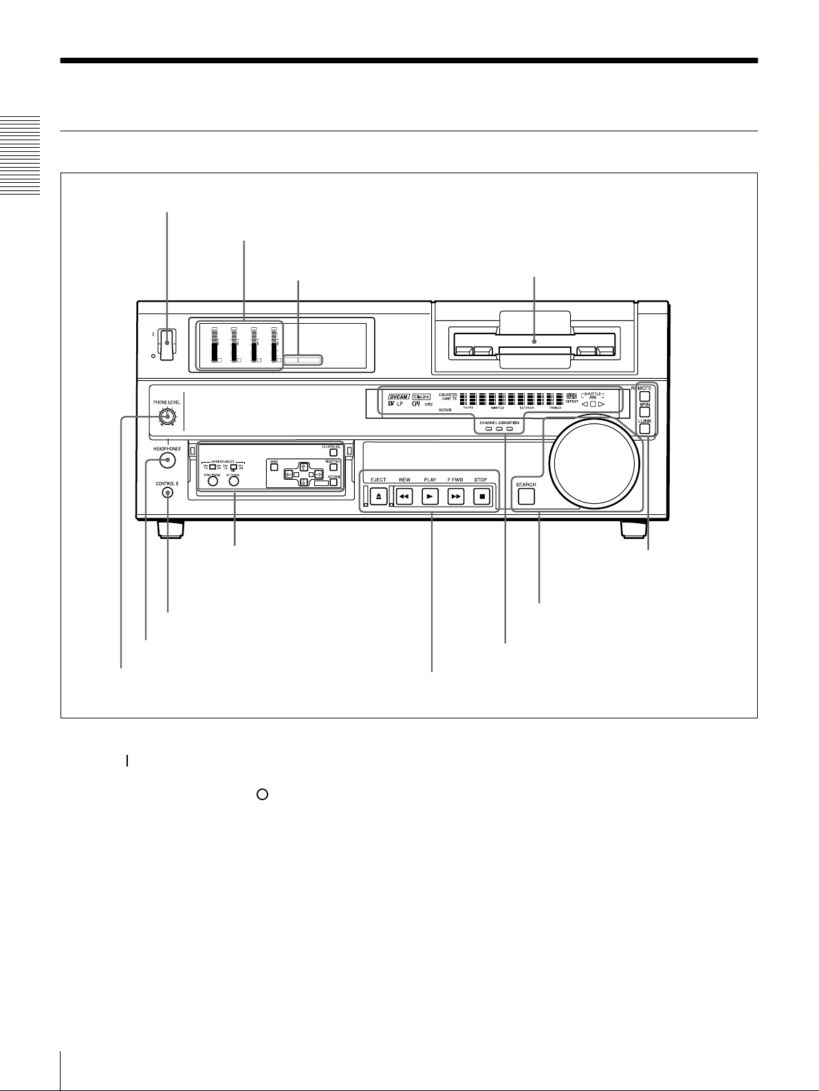
Front Panel
Chapter 1 Overview
a POWER switch
b Audio level meters
d Cassette compartment
E Remote control
setting section
(see page 13)
POWER
c PB FS display
OVER
OVER
OVER
dB
dB
dB
0
0
0
-12
1
-12
-20
0
-20
-1
-30
-30
-40
-40
-2
-60
-60
1
OVER
dB
dB
dB
dB
dB
0
0
0
0
0
1
-12
1
-12
1
0
-20
0
-20
-1
-2
2
0
-1
-1
-30
-30
-40
-40
-2
-2
PB FS
-60
3
48k44.1k32k
-60
4
A B
MARK
A Menu control panel (inside of
the door)
(see page 9)
g CONTROL S connector
f HEADPHONES connector
e PHONE LEVEL control knob
a POWER switch
Press the “” side to power the unit on. When the unit is
powered on, the display windows in the front panel lights.
To power the unit off, press the “” side of the switch.
b Audio level meters
These show the audio levels of channels 1 to 4 during
playback.
c PB FS (playback audio sampling frequency)
display
Indicates the sampling frequency (48 kHz, 44.1 kHz or 32
kHz) at which audio is recorded on tape.
D Search control section
(see page 12)
C Display section
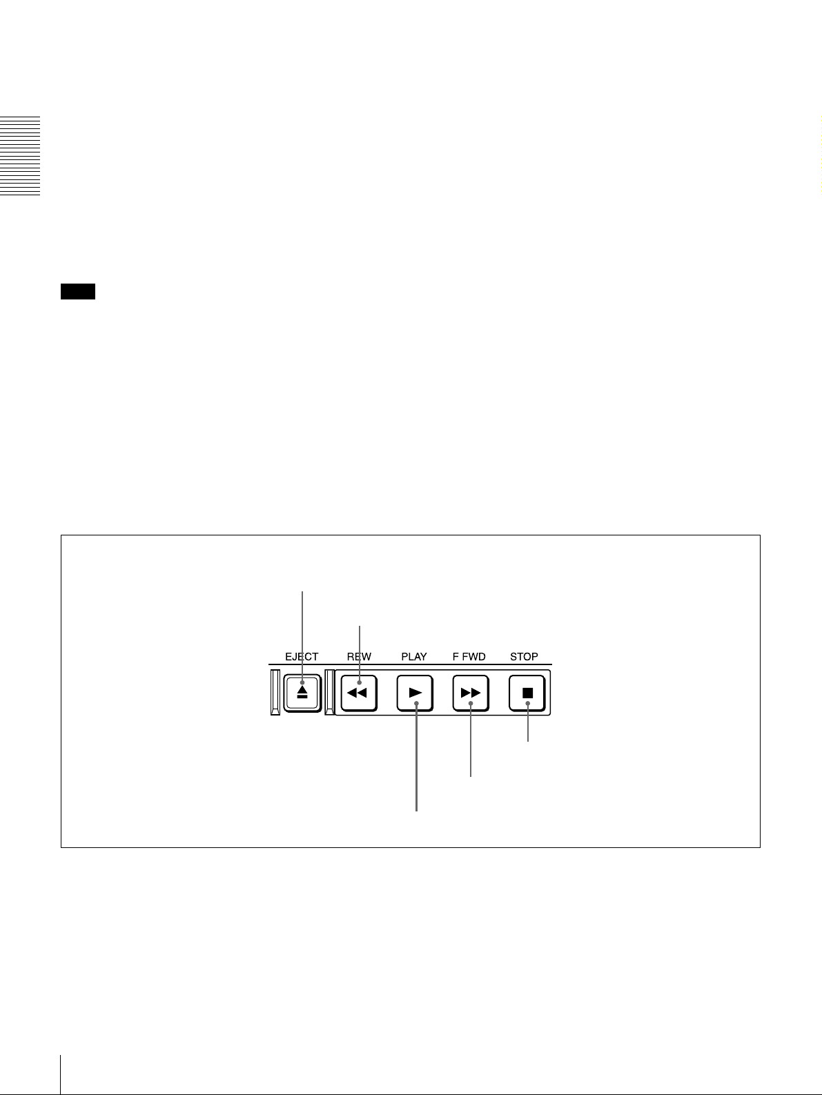
B Tape transport control section
(see page 11)
(see page 10)
d Cassette compartment
Accepts DVCAM, DV and DVCPRO (25M)
videocassettes.
For details of usable cassettes, see page 19.
e PHONE LEVEL control knob
Controls the volume of the headphones connected to the
HEADPHONES connector.
f HEADPHONES connector (stereo phone jack)
Connect stereo headphones for headphone monitoring
during playback.
The audio signal you want to monitor can be selected with
the MONITOR SELECT switches on the menu control
panel.
Location and Function of Parts
8
g CONTROL S connector (stereo minijack)
Connect a SIRCS-compatible remote control unit such as
the DSRM-10.
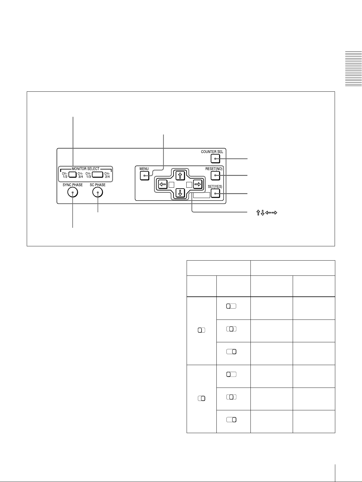
A Menu control panel
The menu control panel is located on the inside of the door
at the lower front of the unit. Pull the top of the door to
open it.
a MONITOR SELECT switches
b MENU button
Chapter 1 Overview
c COUNTER SEL button
MIX
A B
g SC PHASE control
h SYNC PHASE control
a MONITOR SELECT switches
Use these switches to select the channels for audio output
via the AUDIO MONITOR OUT connector on the rear
panel and the HEADPHONES connector on the front
panel.
Use the left switch to select the basic channel setting, then
use the right switch to select the output format (monaural,
stereo, or mix).
The following table lists the correspondence of left/right
switch settings and channel/output format selections.
d RESET (NO) button
MARK
e SET (YES) button
f buttons
Switch setting Selected channel and output
format
Left
switch
Right
switch
HEADPHONES
connector
AUDIO
MONITOR OUT
connector
CH1/3
MIX
CH1/2
CH-
CH-
1/3
3/4
MIX
CH-
1/3
MIX
Channel 1 only
CH2/4
(monaural)
Channels 1 and
CH-
2/4
2 (stereo)
Channel 2 only
CH-
2/4
(monaural)
Channel 1 only
(monaural)
Channels 1 and
2 (mix)
Channel 2 only
(monaural)
CH-
1/3
MIX
CH1/2
CH-
CH-
1/3
3/4
MIX
CH-
1/3
MIX
Channel 3 only
CH-
2/4
(monaural)
Channels 3 and
CH-
2/4
4 (stereo)
Channel 4 only
CH-
2/4
(monaural)
Location and Function of Parts
Channel 3 only
(monaural)
Channels 3 and
4 (mix)
Channel 4 only
(monaural)
9
b MENU button
Press this button to display the menu on the monitor screen
and the time counter display. Press it again to return from
the menu display to the usual display.
On how to use the menu, see Chapter 4 “Menu Settings.”
c COUNTER SEL (selection) button
Selects the type of time data to be shown in the time
Chapter 1 Overview
counter display. Each press of this button cycles through
three indicator display options: COUNTER (CNT: count
value of the time counter), TC (time code), and U-BIT
(user bits).
Note
When the REMOTE button in the remote control setting
section is lit, the COUNTER SEL button does not operate.
In this case, make the time data selection via the remote
equipment that is connected to the REMOTE connector on
the rear panel.
• send a negative response to the prompts issued by the
unit.
e SET (YES) button
Press this button to:
• save new menu settings to the memory of the unit,
• confirm the start and end point settings for repeat
playback, or
• send a positive response to the prompts issued by the
unit.
f Arrow (
JjK k
) buttons
Use these buttons to move around the menu items, and also
to specify and check the repeat playback section.
g SC (subcarrier) PHASE control
Turn this control to accurately adjust the subcarrier phase
of the composite video output signal of the unit with
respect to the reference video signal. Use a cross-point
(Phillips) screwdriver to turn it.
d RESET (NO) button
Press this button to:
• reset menu settings,
• reset the time count (COUNTER) shown in the time
counter display to zero, or
B Tape transport control section
a EJECT button
b REW button
h SYNC (synchronization) PHASE control
Turn this control to accurately adjust the synchronization
phase of the output video signal of the unit with respect to
the reference video signal. Use a cross-point (Phillips)
screwdriver to turn it.
e STOP button
d F FWD button
a EJECT button
When you press this button, it lights and the cassette is
automatically ejected after a few seconds.
b REW (rewind) button
When you press this button, it lights and the tape starts
rewinding (maximum 85 times normal speed). You can
monitor the playback picture during the rewind.
Location and Function of Parts
10
c PLAY button
c PLAY button
When you press this button, it lights and playback begins.
d F FWD (fast forward) button
When you press this button, it lights and the tape is fast
forwarded (maximum 85 times normal speed). You can
monitor the playback picture during the fast forward.
e STOP button
Press this button to stop the current tape transport
operation.
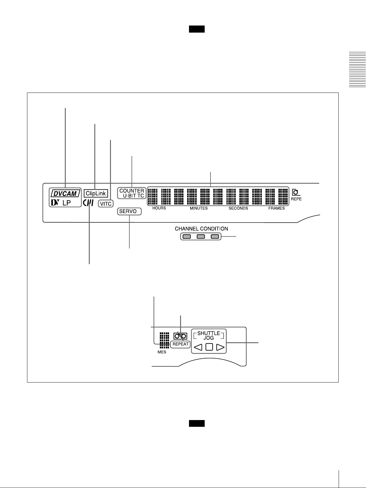
C Display section
a Playback format indicators
b ClipLink indicator
c VITC indicator
d Time data type indicators
Note
No tape transport control buttons other than the EJECT
and STOP buttons will work while the REMOTE button in
the remote control setting section is lit. This can be
changed with the LOCAL ENABLE menu item (see page
40).
Chapter 1 Overview
e Time counter display
g SERVO indicator
f Cassette memory indicator
i REPEAT indicator
a Playback format indicators
DVCAM: This lights when a tape recorded in DVCAM
format is played back.
DV: This lights when a tape recorded in consumer DV
format is played back.
LP: This lights when a tape recorded in LP mode is played
back.
h CHANNEL CONDITION indicators
j Tape end alarm indicator
k SHUTTLE/JOG indicators
When a tape recorded in DVCPRO (25M) format or any
other format than those mentioned above is played back,
none of the above indicators lights.
Note
A tape recorded in LP mode cannot be played back
correctly. When a tape recorded in LP mode is played
back, “DV LP” flashes and audio is muted.
Location and Function of Parts
11

b ClipLink indicator
Lights when a cassette is loaded on which ClipLink log
data is stored in the cassette memory.
For details of ClipLink log data, see the appendix
“ClipLink Guide” (page 73).
c VITC indicator
Lights when VITC is being read regardless of the data
Chapter 1 Overview
shown in the time counter display.
k SHUTTLE/JOG indicators
When searching in shuttle mode using the search dial, the
SHUTTLE indicator lights, and when searching in jog
mode using the search dial, the JOG indicator lights. When
the search dial is turned clockwise causing playback to
take place in the forward direction, the G indicator lights.
When the search dial is turned counterclockwise causing
playback to take place in the reverse direction, the g
indicator lights. When the tape is stopped, the s indicator
lights.
d Time data type indicators
One of the three indicators (COUNTER, U-BIT, and TC)
lights to indicate the type of time data currently shown in
the time counter display.
COUNTER: Count value of the time counter
U-BIT: User bit data
TC: SMPTE time code (for DSR-1600) or EBU time code
(for DSR-1600P)
e Time counter display
Indicates the count value of the time counter, time code,
VITC, or user bit data depending on the settings of the
COUNTER SEL button on the menu control panel and the
TC SELECT menu item (see page 43).
Also used to display error messages and setup menu data.
f Cassette memory indicator
Lights when a cassette provided with a memory chip
(“cassette memory”) is loaded.
g SERVO indicator
This indicator lights when the drum servo and capstan
servo are locked*.
* Servo lock: This refers to the synchronization of the phase of the drum
rotation and the reference signal for the tape transport position, so that the
video heads can trace the same pattern on the tape for playback and
recording.
h CHANNEL CONDITION indicators
These three-color indicators show the state of the playback
signal.
Green: The state of the playback signal is good.
Yellow: The playback signal is somewhat deteriorated, but
playback is possible.
Red: The playback signal is deteriorated. When the red
indicator remains on, head cleaning or an internal
inspection is necessary.
i REPEAT indicator
This indicator lights when the REPEAT MODE menu item
(see page 40) is set to ON.
j Tape end alarm indicator
Starts flashing when the remaining capacity of the tape is
for about 2 minutes.
For more information about the search dial, see “Search
dial” in the next section.
D Search control section
b Search dial
a SEARCH button
a SEARCH button
To use the search dial for playback in shuttle or jog mode,
press this button, turning it on. Pressing the dial toggles
between shuttle and jog modes. In shuttle mode, the
SHUTTLE indicator in the display section lights, and in
jog mode, the JOG indicator in the display section lights.
b Search dial
Turn this to carry out playback in the modes shown in the
following table. Turning the dial clockwise lights the G
indicator in the display section and plays back in the
forward direction. Turning the dial counterclockwise
lights the g indicator in the display section and plays back
in the reverse direction. When the tape is stopped, the s
indicator in the display section lights.
Pressing this dial toggles playback between shuttle mode
and jog mode. When playing back in shuttle mode, the
SHUTTLE indicator in the display section lights, and
when playing back in jog mode, the JOG indicator lights.
You can carry out noiseless playback in the range of ±
times normal speed.
1
/2
Location and Function of Parts
12
Playback modes using the search dial
Playback mode Operation and functions
Shuttle Press the SEARCH button or the search
dial so that the SHUTTLE indicator in
the display section lights, then turn the
search dial.
Playback is carried out at a speed
determined by the position of the search
dial. The maximum shuttle mode
playback speed can be changed with the
SHUTTLE menu item
Jog Press the SEARCH button or the search
dial so that the JOG indicator in the
display section lights, then turn the
search dial. Playback is carried out at a
speed determined by the speed of
rotation of the search dial. The playback
speed is up to
factory default.
The search dial has no detents.
±
(see page 41)
1 times normal speed by
.
You can use the SEARCH ENABLE menu item (see page
40) to select either of the following as the operation to be
performed to put the unit into search mode (shuttle or jog).
• Either press the SEARCH button or turn the search dial
(factory default setting).
• Press the SEARCH button.
this button, turning it on. This requires the optional DSBK1803 board to be installed.
Chapter 1 Overview
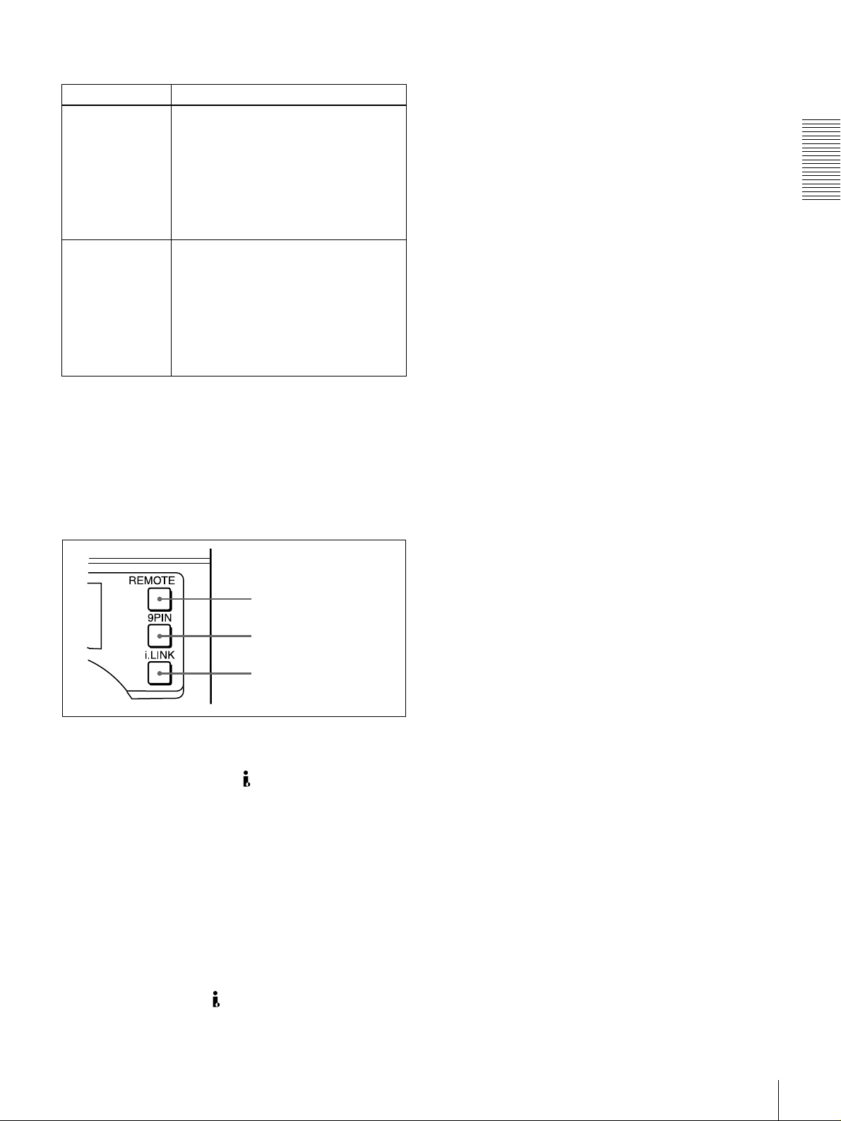
E Remote control setting section
a REMOTE button
b 9PIN button
c i.LINK button
a REMOTE button
When remote-controlling this unit from the unit connected
to the REMOTE connector or DV IN/OUT connector,
press this button, turning it on.
When reverting to local mode to use the buttons in the tape
transport control section, press this button again, turning it
off.
b 9PIN button
When carrying out remote control between this unit and
the unit connected to the REMOTE connector, press this
button, turning it on.
c i.LINK button
When carrying out remote control between this unit and
the unit connected to the DV IN/OUT connector, press
Location and Function of Parts
13
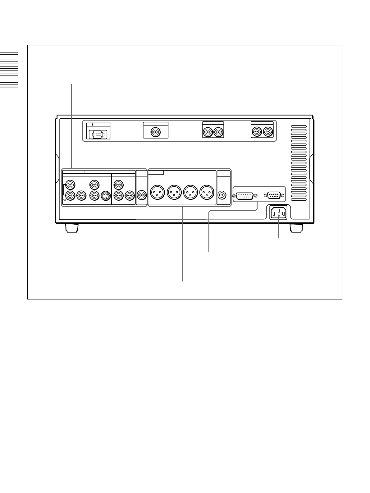
Rear Panel
A Analog video signal output section
Chapter 1 Overview
DV IN/OUT
ANALOG VIDEO
REF. VIDEO
IN OUT OUT
VIDEO
1
2
(SUPER)
S VIDEO
B Digital signal output section
COMPONENT VIDEO
OUT OUT
Y
B-Y
R-Y
TIME
CODE
OUT
SDTI(QSDI)OUT
AUDIO OUT
CH-1
(see page 15)
CH-2 CH-3
(see page 16)
SDI OUT
12
CH-4
MONITOR
OUT
AUDIO
VIDEO CONTROL
AUDIO OUT(AES/EBU)
CH-1/2
CH-3/4
REMOTE
~AC IN
AC IN connector
D External device connectors
(see page 17)
AC IN connector
Use the supplied power cord to connect this to an AC
outlet.
C Analog audio signal output section
(see page 17)
Location and Function of Parts
14
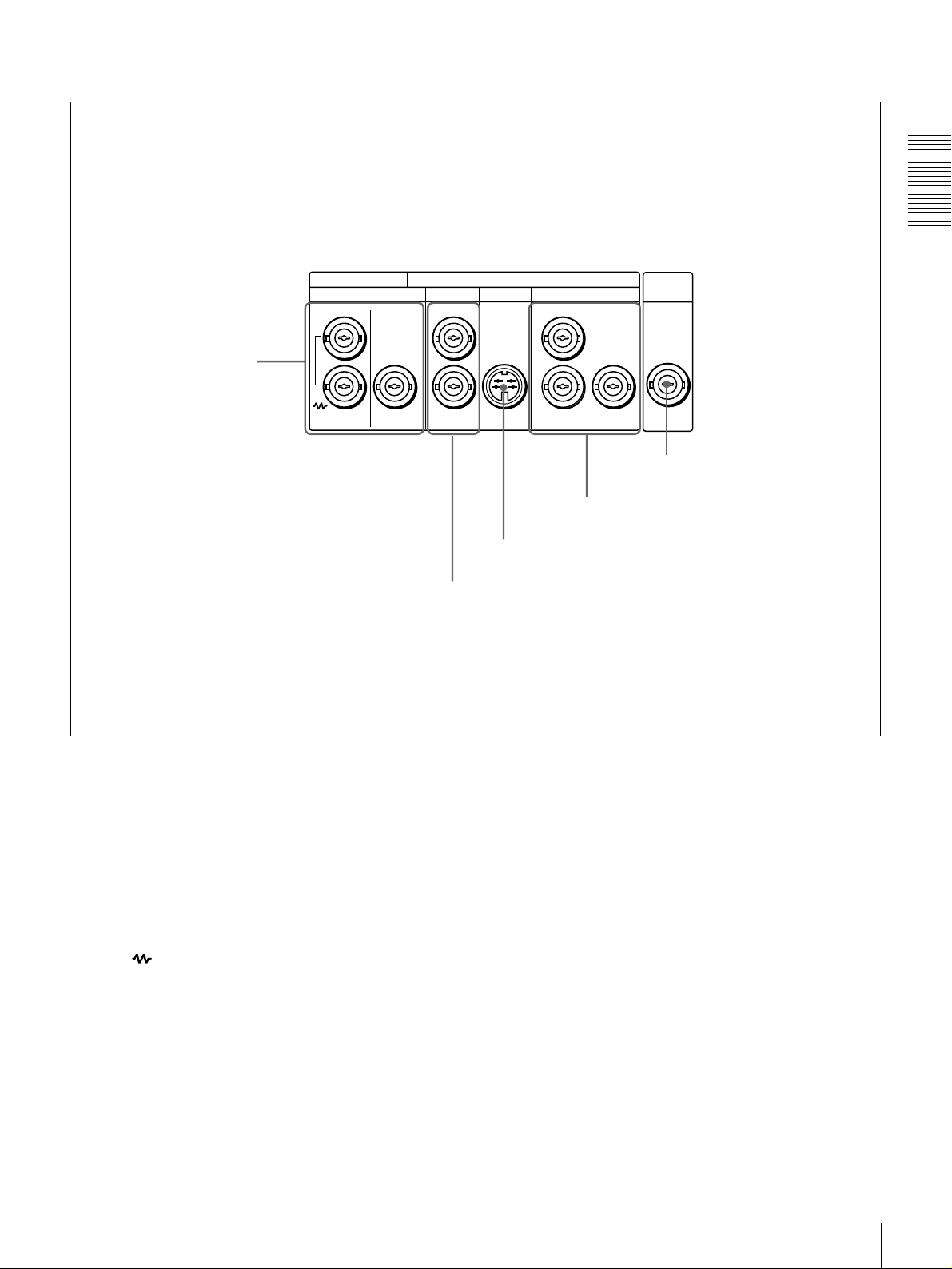
A Analog video signal output section
Chapter 1 Overview
a REF. VIDEO IN/OUT
connectors
ANALOG VIDEO
REF. VIDEO
IN OUT OUT OUT OUT
VIDEO
S VIDEO
1
2
(SUPER)
b VIDEO OUT 1 and 2 (SUPER) connectors
COMPONENT VIDEO
Y
R-Y
c S VIDEO OUT connector
TIME
CODE
OUT
B-Y
e TIME CODE OUT connector
d COMPONENT VIDEO OUT Y/R−Y/B−Y
connectors
a REF. (reference) VIDEO IN/OUT connectors
(BNC type)
Input a reference video signal. The IN connector block has
a built-in automatic 75 Ω termination switch. When a
signal is input to the upper REF. VIDEO IN connector
with no bridging (loop-through) connection made, the
connector is terminated with an impedance of 75 Ω
automatically. To connect the reference video signal input
to the upper REF. VIDEO IN connector also to other
equipment, use the lower REF. VIDEO IN connector
(marked ). When the lower REF. VIDEO IN connector
is used, the built-in 75 Ω termination switch turns off
automatically.
The REF. VIDEO OUT connector outputs a reference
video signal.
b VIDEO OUT 1 and 2 (SUPER) connectors (BNC
type)
These connectors output analog composite video signals.
When the CHARA. DISPLAY menu item (see page 42) is
set to ON (factory default setting), connector 2 (SUPER)
outputs a signal with superimposed text information.
c S VIDEO OUT connector (4-pin)
This connector outputs an S-video signal with separated Y
(luminance) and C (chroma: 3.58 MHz for DSR-1600 or
4.43 MHz for DSR-1600P) components.
d COMPONENT VIDEO OUT Y/R−Y/B−Y
connectors (BNC type)
These connectors output analog component video signals
(Y/R−Y/B−Y).
e TIME CODE OUT connector (BNC type)
Outputs the playback time code.
Location and Function of Parts
15
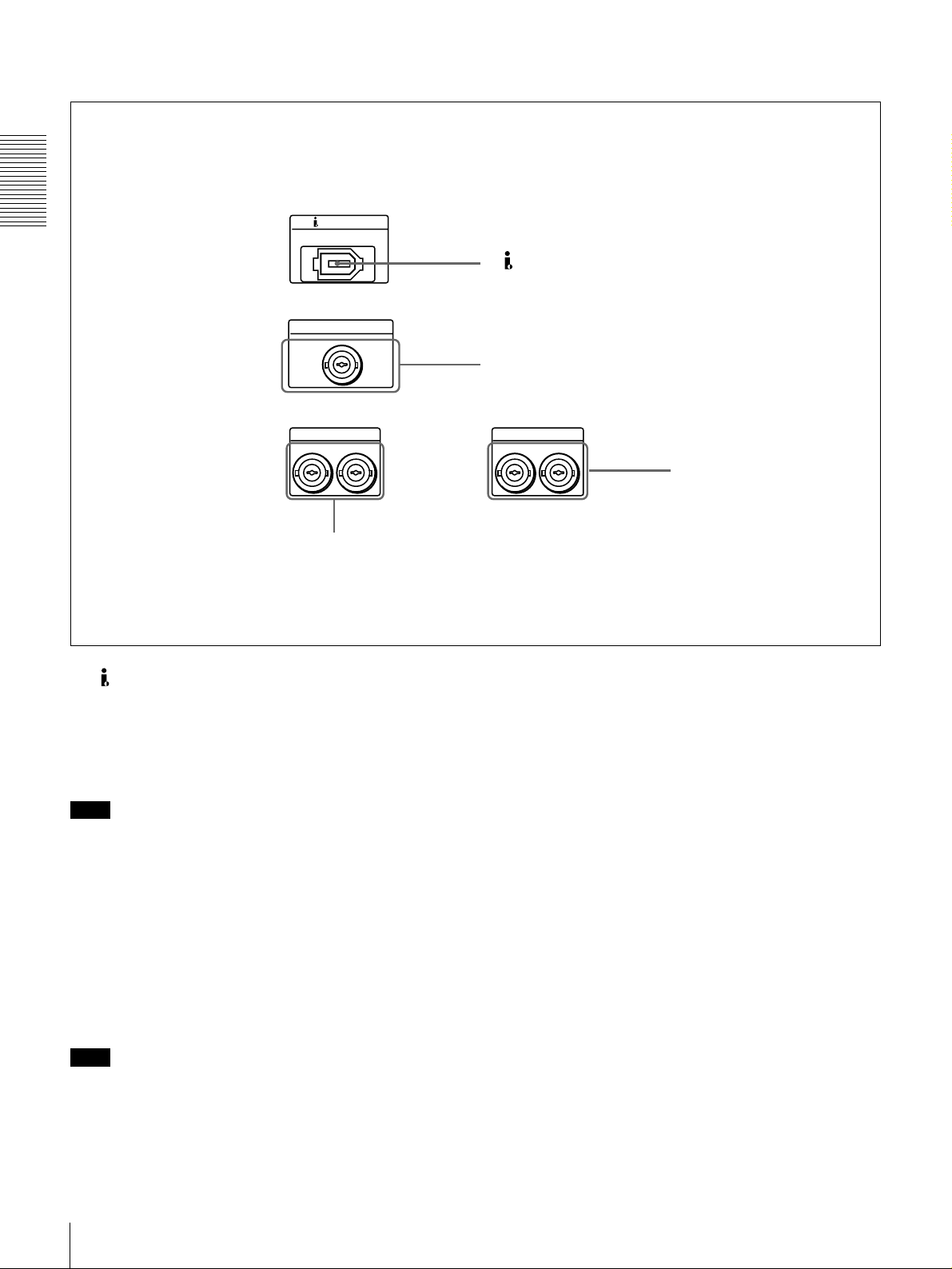
B Digital signal output section (optional DSBK-1601/1602/1803 boards required)
Chapter 1 Overview
DV IN/OUT
SDTI(QSDI)OUT
SDI OUT
2
1
c SDI OUT connectors
a DV IN/OUT connector (6-pin IEEE-1394)
(optional DSBK-1803 i.LINK/DV Input/Output
Board required)
This i.LINK-compatible connector (subsequently referred
to also as the i.DV IN/OUT connector) outputs digital
video and audio signals in DV format.
Note
When searching at speeds in the range +1/2 to +1/30 or
1
−
/2 to −1/30 times normal speed, the audio signal output
from this connector and monitored on external equipment
may sound differently from the audio signal played back
on this unit.
a DV IN/OUT connector
b SDTI (QSDI) OUT connector
AUDIO OUT(AES/EBU)
CH-1/2
CH-3/4
d AUDIO OUT (AES/EBU)
connectors
c SDI (Serial Digital Interface) OUT connectors
(BNC type) (optional DSBK-1601 SDI/AES/EBU
Output Board required)
Output SDI-format digital video and audio signals. The
same signals are output from both connectors.
d AUDIO OUT (AES/EBU) connectors (BNC type)
(optional DSBK-1601 SDI/AES/EBU Output
Board required)
These connectors output digital audio signals in AES/EBU
format. The left connector (CH-1/2) is for audio channels
1 and 2, and the right connector (CH-3/4) is for audio
channels 3 and 4.
b SDTI (QSDI) (Serial Data Transport Interface
(QSDI)) OUT connector (BNC type) (optional
DSBK-1602 SDTI (QSDI) Output Board required)
Outputs digital video and audio signals in SDTI (QSDI)
format.
Note
When searching at speeds in the range +1/2 to +1/30 or
1
−
/2 to −1/30 times normal speed, the audio signal output
from this connector and monitored on external equipment
may sound differently from the audio signal played back
on this unit.
Location and Function of Parts
16
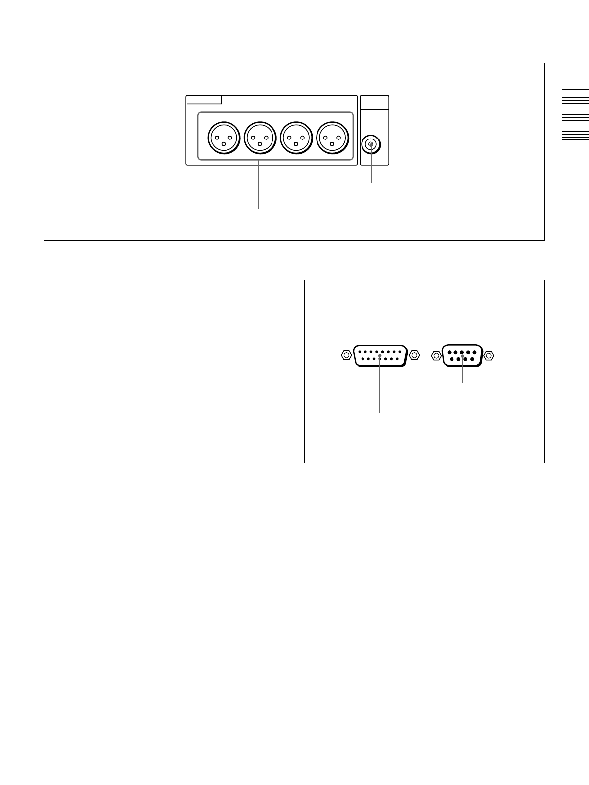
C Analog audio signal output section
AUDIO OUT
CH-1
CH-2 CH-3
a AUDIO OUT CH-1 to CH-4 connectors
a AUDIO OUT CH-1 (channel 1) to CH-4 connectors
(XLR 3-pin, male)
These connectors output channel-1 to channel-4 analog
audio signals, respectively.
It is possible to use the AUDIO OUT CH-3 and AUDIO
OUT CH-4 connectors for audio monitor output for
channels 1 and 2, respectively (use the OUTPUT CH3/4
menu item (see page 45).
b AUDIO MONITOR OUT connector (RCA phono
jack)
This connector outputs audio signals for monitoring. The
audio signals to be output from this connector can be
selected with the MONITOR SELECT switches on the
menu control panel.
MONITOR
OUT
CH-4
AUDIO
b AUDIO MONITOR OUT connector
D External device connectors
VIDEO CONTROL
a VIDEO CONTROL connector
REMOTE
b REMOTE connector
Chapter 1 Overview
a VIDEO CONTROL connector (D-sub 15-pin)
For remote control of the internal digital video processor,
connect an optional remote control unit such as the UVR60/60P or BVR-50/50P to this connector.
b REMOTE connector (D-sub 9-pin)
When controlling this unit from an editing control unit
such as the ES-3, ES-7, PVE-500, BVE-600/800/910/
2000, or RM-450/450CE, connect the unit to the editing
control unit via this connector using the optional 9-pin
remote control cable.
Location and Function of Parts
17

Chapter 1 Overview
Location and Function of Parts
18

Playback
Usable Cassettes
Playback
This section describes the necessary settings and operations to perform playback
on this unit. The same settings and operations apply whether you are using the
unit as part of an editing system, for dubbing, or as a stand-alone player VCR.
For the necessary connections and settings not covered in this section, see
Chapter 5 “Connections and Settings.”
This unit can use the DVCAM cassettes listed below.
Model name Size
PDV-64ME/94ME/124ME/184ME Standard size
PDVM-12ME/22ME/32ME/40ME Mini size
Chapter
2
The numbers in each model name indicate the maximum playback time (in
minutes) for each model. For example, the PDV-184ME has a maximum
playback time of 184 minutes.
Other usable cassettes
All consumer DV cassettes and large- and medium-size DVCPRO (25M)
cassettes can also be played back on this unit.
Notes
• If you insert an incorrect type of cassette, it will be automatically ejected.
• You can also use DV cassettes on the unit. However, it is the best choice to
always use DVCAM cassettes because they are more reliable than DV
cassettes whatever your purpose may be: playback, editing, or long-period
storage of recordings.
Playback
19
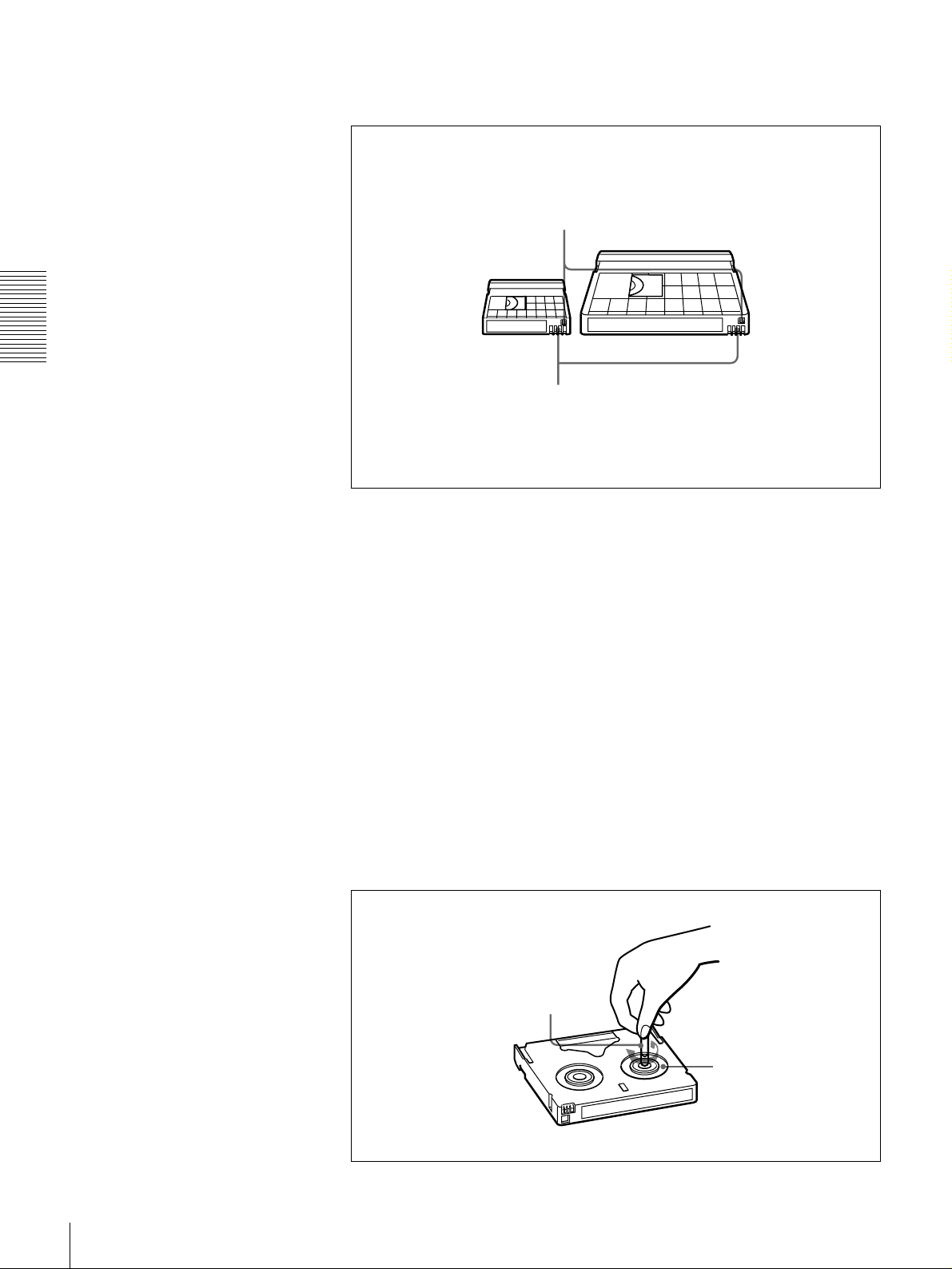
DVCAM cassettes
Chapter 2 Playback
Notes on using cassettes
The following figure illustrates the DVCAM cassettes.
REC/SAVE switch
Set to SAVE to prohibit recording on the tape.
Mini size Standard size
Cassette memory
This memory is used to store ClipLink log data.
For details of ClipLink log data, see the appendix
“ClipLink Guide” (page 73).
• Before storing the cassette for a long period of time, rewind the tape to the
beginning and be sure to put the cassette in its storage case, preferably on end
instead of flat on its side.
Storing a cassette in any other condition (not rewound, out of its case, etc.)
may cause the video and audio contents to become damaged over time.
• If the cassette memory connector (contact point) becomes dirty, connection
problems may occur, causing a loss of functions. Remove away any dust or
dirt from this area before using the cassette.
• If the cassette is dropped on the floor or otherwise receives a hard impact, the
tape may become slackened and may not play back correctly.
Checking the tape for slack
For information about how to check the tape for slack, see the next section.
Using a paper clip or a similar object, turn the reel gently in the direction shown
by the arrow. If the reel does not move, there is no slack. Insert the cassette into
the cassette compartment, and after about 10 seconds take it out.
Paper clip, etc.
Reel
20
Playback
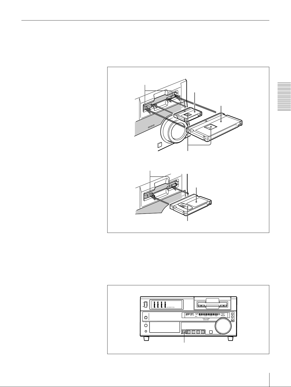
Inserting and Ejecting Cassettes
Inserting a cassette
This unit accepts three sizes of cassette: L (standard size), M (medium size:
DVCPRO) and S (mini size). When inserting a cassette in the unit, make sure
its tape window faces upward as shown in the following figure.
Outer guides
Inner guides
Mini size (Insert the cassette into the
middle of the cassette compartment.)
Standard size
Chapter 2 Playback
Tape window facing upward
Medium size (Align the cassette with
the outer guides, then slide it in over
the inner guides.)
Tape window facing upward
No double insertion of cassettes
When you insert a cassette, the orange lock-out plate appears in the cassette
compartment to prevent double insertion.
Ejecting a cassette
Press the EJECT button.
OVER
OVER
OVER
OVER
dB
dB
dB
dB
dB
dB
dB
dB
0
0
0
0
0
0
0
0
-12
1
-12
1
-12
1
-12
1
-20
0
-20
0
-20
0
-20
0
-1
-1
-1
-1
-30
-30
-30
-30
-40
-40
-40
-40
-2
-2
-2
-2
PB FS
-60
1
48k44.1k32k
-60
-60
-60
2
3
4
EJECT button
Playback
21
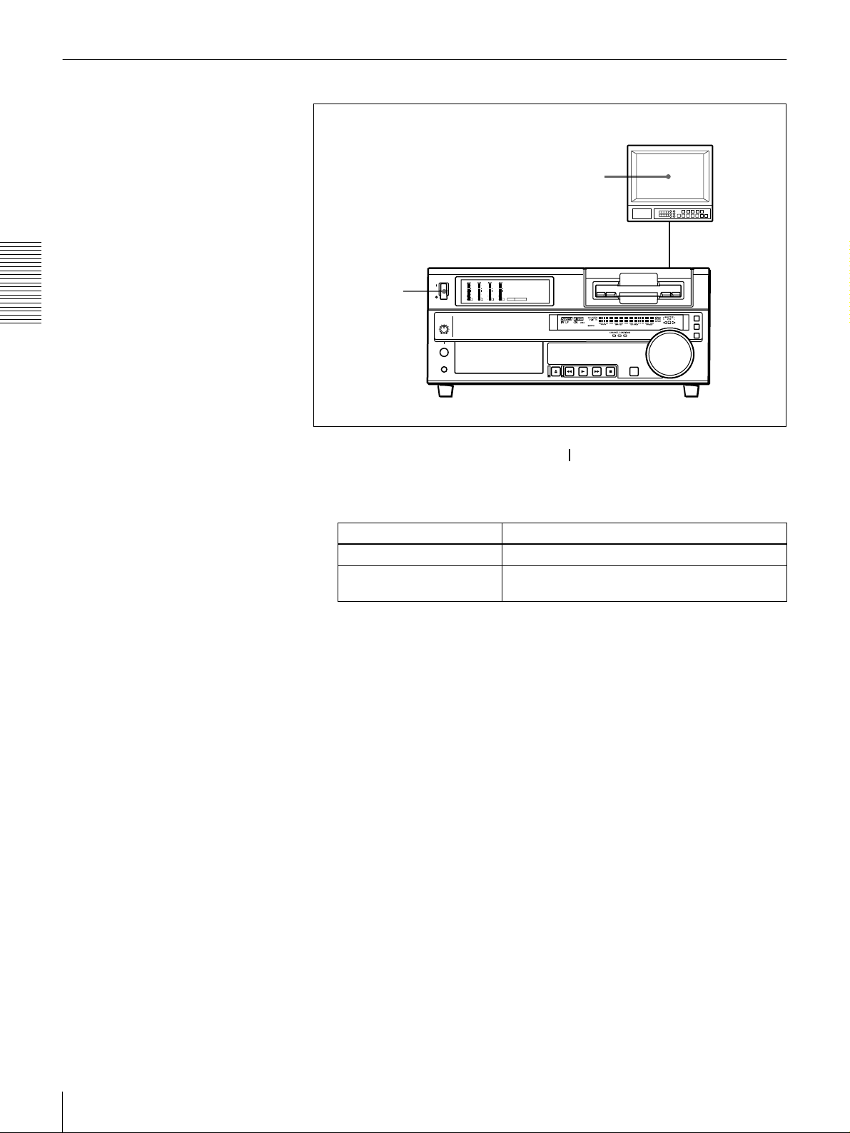
Settings for Playback
Chapter 2 Playback
Video monitor
2
Player (DSR-1600/1600P)
OVER
OVER
OVER
OVER
dB
dB
dB
dB
dB
dB
dB
dB
0
0
0
0
0
0
0
0
-12
1
-12
1
-12
1
-12
1
-20
0
-20
0
-20
0
-20
0
-1
-1
-1
-1
-30
-30
-30
-30
-40
-40
-40
-40
-2
-2
-2
-2
PB FS
1
1
Power on this unit by pressing on the side of the POWER switch.
-60
1
48k44.1k32k
-60
-60
-60
2
3
4
2
Power on the video monitor and set its switches as shown below.
Switch Setting
75 Ω termination switch ON (or attach a 75 Ω terminator.)
Input switch Set according to the type of input signal from this
unit.
22
Playback
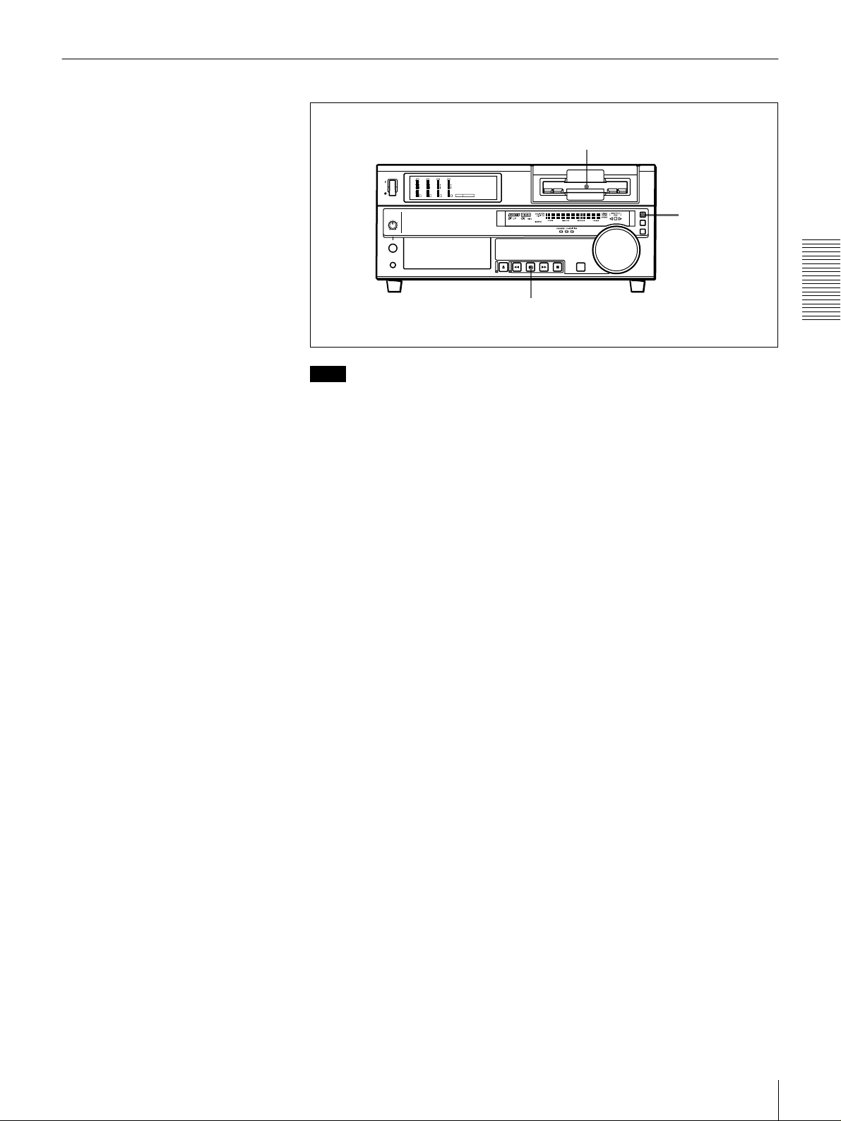
Playback Procedure
1
OVER
OVER
OVER
OVER
dB
dB
dB
dB
dB
dB
dB
dB
0
0
0
0
0
0
0
0
-12
-12
-12
-12
1
1
1
1
-20
-20
-20
-20
0
0
0
0
-1
-1
-1
-1
-30
-30
-30
-30
-40
-40
-40
-40
-2
-2
-2
-2
PB FS
-60
1
48k44.1k32k
-60
-60
-60
2
3
4
REMOTE button
2
Note
When controlling this unit from an editing control unit connected to the
REMOTE connector on this unit, press the REMOTE button to turn it on. When
not, turn the button off.
1
Insert a cassette.
For details of cassette insertion see page 21, and for usable cassette types
see page 19.
The cassette is automatically drawn into the unit. The STOP button will
light, and a few seconds later a still image will appear on the monitor screen.
2
Press the PLAY button.
This starts the playback operation. When the tape is played back all the way
to the end, the unit automatically rewinds it and then stops.
Chapter 2 Playback
Playback
23
If the following indicators light when a cassette is loaded
Indicator It means:
Cassette memory indicator The loaded cassette contains a cassette memory.
ClipLink indicator There is ClipLink log data stored in the cassette
memory on the loaded cassette.
To perform the following operations
Operation Do this:
Stop playback. Press the STOP button.
Chapter 2 Playback
Adjust the audio playback
level.
Play back in shuttle mode
while monitoring the video.
Play back in jog mode while
monitoring the video.
Inhibit the unit from
outputting text information
(time data, operation mode
indications, etc.) to the
video monitor.
Remove the cassette. Press the EJECT button.
Disable the automatic
rewind function.
Change the time period
before the unit switches
from stop mode to standby
off mode.
The unit enters stop mode, and will automatically
switch to standby off mode after the time set with the
STOP TIMER menu item
(see page 43)
.
Use the audio level control on the monitor.
Press the SEARCH button or search dial to light the
SHUTTLE indicator in the display section, then rotate
the search dial.
Playback is carried out at the speed determined by
the angular position of the search dial.
The maximum speed for shuttle playback can be
changed using the SHUTTLE menu item
.
41)
(see page
Press the SEARCH button or search dial to light the
JOG indicator in the display section, then rotate the
search dial.
Playback is carried out at the speed according to the
speed of the search dial rotation. The playback
speed range is ±1 times normal speed by factory
default.
The search dial has no detents.
Set the CHARA. DISPLAY menu item
(see page 42)
to OFF.
If a CNT value is shown on the time counter display,
the CNT value is reset.
Set the AUTO REW menu item
(see page 41)
to
DISABLE.
Change the setting of the STOP TIMER menu item
(see page 43)
.
24
Playback
Repeat Playback—Automatic Cyclical Playback
Proceed as follows to perform automatic cyclical playback of recording (repeat
playback) between selected start and end points.
1
Set the desired repeat start and end points using the REPEAT FUNCTION
menu item (see page 40).
You can set points A and B as start and end points by following the
procedure described in the next section.
2
Set the REPEAT MODE menu item (see page 40) to ON.
The REPEAT indicator lights.
3
Press the SET (YES) button to save the new setting and close the menu.
4
Press the PLAY button.
The unit repeats playback between the repeat start and end points set in step
1.
Setting Points A and B for Repeat Playback
You can set the repeat playback start point (point A) and end point (point B) by
using the current tape position or inputting time code values.
To perform repeat playback after setting points A and B, press the PLAY button
when the REMOTE button is off. When the DSRM-10 Remote Control Unit is
connected to the CONTROL S connector on the front panel, you can also start
repeat playback by pressing its PLAY button with the REMOTE button of this
unit off.
Chapter 2 Playback
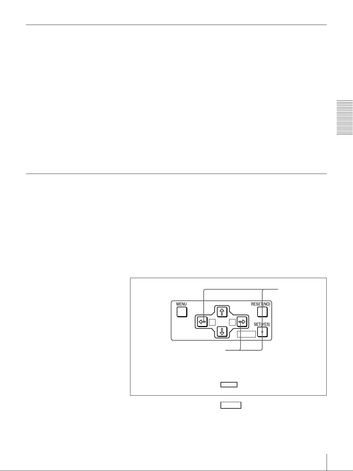
Setting the current tape position as point A or B
Proceed as follows to set the current tape position as point A or B for repeat
playback.
Buttons used for setting the
current tape position as point B
In the following explanation of how to set points A and B for repeat
playback, these three buttons are referred to as the KA button,
Bk button, and SET (YES) button, respectively.
While holding down the SET (YES) button on the menu control panel,
press the KA or Bk button. The time code value of the current tape
position is set as point A or B, and a message “A set” or “B set” is displayed for
0.5 second in the time counter display.
Buttons used for
setting the current
tape position as
point A
A B
MARK
MARK
MARK
Playback
25
Once set, the point A or B time code value is held in the non-volatile memory
of the unit until changed. It is not lost when the unit is powered off.
Note
When setting point A or B, you can only use a time code value. Even when
COUNTER is selected with the COUNTER SEL button, you cannot use a CNT
value to set point A or B.
To check the point A or B time code value
Press the KA or Bk button on the menu control panel. While the button is
held down, the point A or B time code value is displayed on the monitor and in
the time counter display.
If you hold down the KA and Bk buttons simultaneously, the value shown
is the point B time code value minus the point A time code value. If the point A
time code value is greater than the point B time code value, a minus sign (−) is
shown before the value.
Chapter 2 Playback
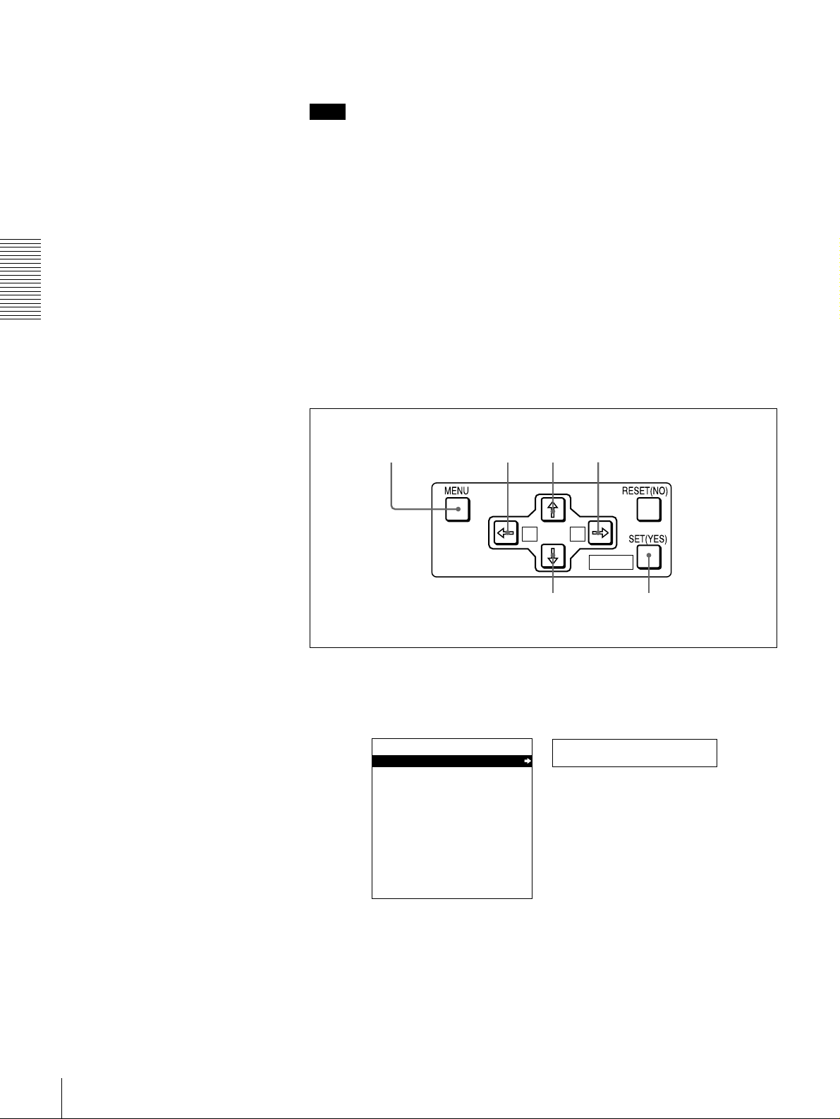
Inputting time code values for points A and B
Using the following procedure, you can modify the time code value for point A
or B.
1,15
1
Press the MENU button.
The following menu display appears.
SYSTEM MENU
SETUP MENU
HOURS METER
8,11 12 2,3,4,6,10,11
A B
MARK
5,7,9,12 13
Setup menu
Time counter display
26
Monitor screen
Playback
 Loading...