


25-DSR
3-073-884-12(1)
Digital
Videocassette
Recorder
Operating Instructions |
|
GB |
|
|
|
||
|
|
|
|
Mode d’emploi |
|
|
FR |
DSR-25
2002 Sony Corporation
WARNING
To prevent fire or shock hazard, do not expose the unit to rain or moisture.
To avoid electrical shock, do not open the cabinet. Refer servicing to qualified personnel only.
THIS APPARATUS MUST BE EARTHED.
This symbol is intended to alert the user to the presence of uninsulated “dangerous voltage” within the product’s enclosure that may be of sufficient magnitude to constitute a risk of electric shock to persons.
This symbol is intended to alert the user to the presence of important operating and maintenance (servicing) instructions in the literature accompanying the appliance.
Important Safety Instructions
•Read these instructions.
•Keep these instructions.
•Heed all warnings.
•Follow all instructions.
•Do not use this apparatus near water.
•Clean only with dry cloth.
•Do not block any ventilation openings.
Install in accordance with the manufacturer’s instructions.
•Do not install near any heat sources such as radiators, heat registers, stoves, or other apparatus (including amplifiers) that produce heat.
•Do not defeat the safety purpose of the polarized or grounding-type plug. A polarized plug has two blades with one wider than the other. A grounding-type plug has two blades and a third grounding prong. The wide blade or the third prong are provided for your safety. If the provided plug does not fit into your outlet, consult an electrician for replacement of the obsolete outlet.
•Protect the power cord from being walked on or pinched particularly at plugs, convenience receptacles, and the point where they exit from the apparatus.
•Only use attachments/accessories specified by the manufacturer.
•Use only with the cart, stand, tripod, bracket, or table specified by the manufacturer, or sold with the
apparatus.
When a cart is used, use caution when moving the cart/apparatus combination to avoid injury from tip-over.
•Unplug this apparatus during lightning storms or when unused for long periods of time.
•Refer all servicing to qualified service personnel. Servicing is required when the apparatus has been damaged in any way, such as power-supply cord or plug is
damaged, liquid has been spilled or objects have fallen into the apparatus, the apparatus has been exposed to rain or moisture, does not operate normally, or has been dropped.
Owner’s record
The model number is located at the front of the unit and the serial number on the left. Record the serial number in the space provided below. Refer to these numbers whenever you call upon your Sony dealer regarding this product.
Model No. DSR-25 Serial No. ______________________
2 (GB)
Notes on installation
•This unit is not designed as a portable. Make sure to install the unit properly on a flat surface. If you install the unit so that it is inclined 30 degrees or more (i.e., if you stand the unit on its side), malfunctions may occur.
•Do not place materials around the unit that may block the ventilation holes. Otherwise, heat builds up inside the unit and malfunctions may occur.
For customers in Europe
This product with the CE marking complies with both the EMC Directive (89/336/EEC) and the Low Voltage Directive (73/23/EEC) issued by the Commission of the European Community.
Compliance with these directives implies conformity to the following European standards:
•EN60065: Product Safety
•EN55103-1: Electromagnetic Interference (Emission)
•EN55103-2: Electromagnetic Susceptibility (Immunity) This product is intended for use in the following Electromagnetic Environment(s):
E1 (residential), E2 (commercial and light industrial), E3 (urban outdoors) and E4 (controlled EMC environment, ex. TV studio).
For the customers in the Netherlands
Voor de klanten in Nederland
•Dit apparaat bevat een vast ingebouwde batterij die niet vervangen hoeft te worden tijdens de levensduur van het apparaat.
•Raadpleeg uw leverancier indien de batterij toch vervangen moet worden. De batterij mag alleen vervangen worden door vakbekwaam servicepersoneel.
•Gooi de batterij niet weg maar lever deze in als klein chemisch afval (KCA).
•Lever het apparaat aan het einde van de levensduur in voor recycling, de batterij zal dan op correcte wijze verwerkt worden.
For customers in the U.S.A.
If you have any questions about this product, you may call: Sony’s Business Information Center (BIC) at 1-800- 686-SONY (7669)
or Write to: Sony Customer Information Services Center 6900-29 Daniels Parkway, PMB 330 Fort Myers, Florida 33912
Declaration of Conformity
Trade Name: |
SONY |
Model: |
DSR-25 |
Responsible Party: |
Sony Electronics Inc. |
Address: |
16450 W. Bernardo Dr, San |
|
Diego, CA 92127 U.S.A. |
Telephone Number: |
858-942-2230 |
This device complies with Part 15 of the FCC Rules. Operation is subject to the following two conditions:
(1)This device may not cause harmful interference, and
(2)this device must accept any interference received, including interference that may cause undesired operation.
CAUTION
You are cautioned that any changes or modifications not expressly approved in this manual could void your authority to operate this equipment.
Notes
•This equipment has been tested and found to comply with the limits for a Class B digital device, pursuant to Part 15 of the FCC Rules. These limits are designed to provide reasonable protection against harmful interference in a residential installation. This equipment generates, uses, and can radiate radio frequency energy and, if not installed and used in accordance with the instructions, may cause harmful interference to radio communications. However, there is no guarantee that interference will not occur in a particular installation. If this equipment does cause harmful interference to radio or television reception, which can be determined by turning the equipment off and on, the user is encouraged to try to correct the interference by one or more of the following measures:
•Reorient or relocate the receiving antenna.
•Increase the separation between the equipment and receiver.
•Connect the equipment into an outlet on a circuit different from that to which the receiver is connected.
•Consult the dealer or an experienced radio/TV technician for help.
•This product contains mercury. Disposal of this product may be regulated if sold in the United States. For disposal or recycling information, please contact your local authorities or the Electronics Industries Alliance (http://www.eiae.org).
Caution
Television programs, films, video tapes and other materials may be copyrighted. Unauthorized recording of such material may be contrary to the provisions of the copyright laws. Also, use of this recorder with cable television transmission may require authorization from the cable television transmission and/or program owner.
GB
English
3 (GB)

TableTableof CofntentsContents
Chapter1
Overview
Chapter2
Features .................................................................... |
6 |
(GB) |
|
DVCAM Format ......................................................... |
6 |
(GB) |
|
Other Features ............................................................ |
7 |
(GB) |
|
Location and Function of Parts .............................. |
9 |
(GB) |
|
Front Panel ................................................................. |
9 |
(GB) |
|
Rear Panel ................................................................ |
18 |
(GB) |
|
Supplied Remote Commander ................................. |
21 |
(GB) |
|
Displaying Various Data ......................................... |
23 |
(GB) |
|
Playback and
Recording
Chapter3
Notes on Video Cassettes ..................................... |
26 (GB) |
Inserting/Ejecting Cassettes ..................................... |
27 (GB) |
Notes on Playback/Recording .................................. |
28 (GB) |
Playback .................................................................. |
29 (GB) |
Connections for Playback ......................................... |
29 (GB) |
Settings for Playback ................................................ |
31 (GB) |
Playback Procedures ................................................ |
31 (GB) |
Playback Functions .................................................. |
32 (GB) |
Recording ............................................................... |
37 (GB) |
Connections for Recording ....................................... |
37 (GB) |
Settings for Recording .............................................. |
39 (GB) |
Recording Procedure ................................................ |
40 (GB) |
Recording Functions ................................................ |
40 (GB) |
Setting the Time
Code
Setting the Time Code and User Bits ................... |
42 (GB) |
Using the Internal Time Code Generator ................. |
42 (GB) |
Chapter4
Duplication and
Audio Dubbing
Duplication (generating a work tape with the same
time code) ...................................................... |
47 (GB) |
Audio Dubbing ....................................................... |
52 (GB) |
4 (GB) |
Table of Contents |

Chapter5
Adjusting and
Setting Through
Menus
Operating the Menus ............................................. |
54 (GB) |
Menu Organization ................................................... |
55 (GB) |
Menu Contents ......................................................... |
56 (GB) |
Chapter6
Maintenance
Appendix
Troubleshooting ..................................................... |
68 (GB) |
Alarm Messages ..................................................... |
72 (GB) |
Notes on Use .......................................................... |
73 (GB) |
Notes on the Videocassette Recorder ....................... |
73 (GB) |
Cleaning of the Video Heads .................................... |
73 (GB) |
Notes on the Video Cassettes ................................... |
74 (GB) |
Notes on the LCD Screen ......................................... |
74 (GB) |
About Moisture Condensation ................................. |
74 (GB) |
Digital Hours Meter ................................................. |
75 (GB) |
Self-diagnostics Function ......................................... |
75 (GB) |
Compatibility of DVCAM and DV Format ............. |
76 (GB) |
Specifications ......................................................... |
78 (GB) |
Glossary .................................................................. |
80 (GB) |
Index ........................................................................ |
82 (GB) |
Submenu Index ...................................................... |
83 (GB) |
Table of Contents |
5 (GB) |

Features
Overview 1 Chapter
Chapter1
Overview
Features
The DSR-25 is a digital videocassette recorder using 1/4-inch tape. Offering the DVCAM™ digital recording format, the DSR-25 produces stable, superior picture quality by digitally processing and separating image signals into color difference signals and a luminance signal (component video). The DSR-25 can handle both NTSC and PAL color systems and is equipped with an analog interface as well as a digital interface enabling connection to a digital device such as a computer. The built-in color LCD monitor lets you check images easily.
The main features of the DSR-25 are described below.
DVCAM Format
DVCAM is based on the consumer DV format, which uses the 4:1:1 component digital format (NTSC) or the 4:2:0 format (PAL), and provides a 1/4-inch digital recording format for professional use.
For details, see “Compatibility of DVCAM and DV Format” on page 76 (GB).
High picture quality, high stability
Video signals are separated into color difference signals and a luminance signal, which are encoded and compressed to one-fifth size before being recorded to ensure stable and superb picture quality.
Because the recording is digital, multi-generation digital dubbing can be performed with virtually no deterioration of quality.
Wide track pitch
The recording track pitch is about 15 µm, fully 50 percent wider than the DV format’s 10 µm track pitch. Thanks to this feature, the DVCAM format fully meets the reliability and precision requirements of professional editing.
High-quality PCM digital audio
PCM recording makes for a wide dynamic range and a high signal-to-noise ratio, thereby enhancing sound quality.
There are two recording modes: 2-channel mode (48 kHz sampling and 16 bit linear code), which offers sound quality equivalent to the DAT (Digital Audio Tape) format, or 4-channel mode (32 kHz sampling and 12 bit nonlinear code).
6 (GB) |
Chapter 1 Overview |

|
|
|
|
|
|
DV format compatibility |
|
Digital slow playback |
The unit can perform recording and playback in the |
|
The unit has a frame memory function that allows slow |
DV-format (SP mode only). (Recording/playing an |
|
playback without noise. This is available only at +1/3- |
image in LP mode is not available.) |
|
time speed and –1/3-time speed. |
NTSC/PAL systems compatible
The unit is compatible with NTSC and PAL systems. With DV connection or in the playback mode, the color system of signals is detected automatically. The color system select switch on the unit allows input of analog video signals in either color system. This compatibility allows you to record (download) or play back (upload) both NTSC and PAL formatted signals with your VCR, computer, or other equipment. However, the unit cannot convert the color system of the signals.
Choice of two cassette sizes
The unit can use both standard-size and mini-size DVCAM/DV cassettes.
•According to cassette size, the position of the reel drive plates automatically changes.
•The maximum recording/playback times are 184 minutes for standard size cassettes and 40 minutes for mini-size cassettes (DVCAM format).
Remote control
The unit can be operated by remote control from the CONTROL S system Remote Control Unit (DSRM20, not supplied).
High-speed search function
If you use the Remote Control Unit (DSRM-20, not supplied), the unit has a picture search function that allows you to view color pictures at playback speeds up to 14 times normal speed (NTSC) or up to 17 times normal speed (PAL) in both forward and reverse directions.
You can also search frame-by-frame in jog mode. While searching for scenes, you can also hear playback audio.
Time code and user bits
On this unit, you can use time code and user bits. Using the menu, these can be set easily.
Jog audio function
If you use the Remote Control Unit (DSRM-20, not supplied), audio can be monitored at various playback speeds when in jog mode.
Other Features
Built-in color LCD monitor
The unit has a 2-type color LCD (liquid crystal display) monitor that lets you verify images on the spot. You can see the setup menus, audio levels, and system statuses. Menus and data can be superimposed over the picture being displayed.
Duplicate, including cassette memory data
Using an i.LINK cable, you can duplicate a tape that includes time code and cassette memory data, etc. If the original tape has blank portions, you can duplicate the tape skipping those portions.
Audio dubbing function
The unit allows you to record just the sound onto the recorded tape (audio dubbing). (To dub sounds, you are allowed to use only channel 3 and 4 of the tape recorded in DVCAM format, the audio mode of which is 32 kHz.)
Overview 1 Chapter
Chapter 1 Overview |
7 (GB) |

Features
Overview 1 Chapter
Menu system for functionality and operation settings
The unit provides a menu system to make its various functions easier to use and set up.
Superimposition function
Time code, warnings, menus, and other text data can be output as analog video signals and can be superimposed on the image output to the LCD monitor.
Easy maintenance functions
•Self-diagnostics/alarm functions: The system automatically detects an invalid operation, an invalid connection or a malfunction, and displays a description, a cause and a recovery method on the LCD monitor and outputs the data as analog video signals.
•Digital hours meter: A digital hours meter counts four types of time data—operating time, drum rotation time, tape running time, and tape threading/ unthreading. The digital hours data are indicated on the menu.
......................................................................................
 ,
,  ,
, 

 and
and 
 are trademarks of Sony Corporation.
8 (GB) |
Chapter 1 Overview |

Location and Function of Parts
Front Panel
1 Cassette compartment |
|
4Display window |
|
|
(see page 16 (GB)) |
2 KEY INH switch |
|
|
|
|
qa EJECT button |
3 ON/STANDBY |
|
|
switch and |
1 |
DSR-25 |
|
||
lamp |
|
FIX VAR |
|
|
|
|
KEY INH |
|
|
ON OFF |
|
4 TIMER selector |
|
|
AUDIO OUTPUT |
CH-1 |
|
SELECT |
||
|
|
(DUB CH-3) |
CH- |
CH- |
3 Audio control section |
1/2 |
3/4 |
|
5 AUDIO OUTPUT |
NTSC |
(see page 15 (GB)) |
PAL |
||
SELECT selector |
|
|
MIN |
MAX |
CH-2 |
|
|
|
6 PHONE LEVEL |
|
(DUB CH-4) |
|
|
|
control knob |
|
|
7 PHONES jack |
|
|
|
|
2 Tape transport control |
|
|
section |
8 RESET button |
|
(see page 13 (GB)) |
|
|
|
1 Monitor display section |
|
0 INPUT SELECT |
|
selector |
|
(see page 11 (GB)) |
|
|
|
|
|
9 CHARACTER DISPLAY switch |
|
|
1 Cassette compartment |
3 ON/STANDBY switch and lamp |
|
Insert a standard-size or mini-size DVCAM cassette. |
Press this switch to turn the unit on. The ON/ |
|
To open or close the compartment, press the EJECT |
STANDBY lamp lights up in green. When you press |
|
button qa. |
this switch again, the unit goes into the standby mode |
|
For details of cassettes that can be used, see “Notes on |
and the lamp lights up in red. |
|
Video Cassettes” on page 26 (GB). |
|
|
|
Note |
|
2 KEY INH (key inhibit) switch
Turning on this switch disables all of buttons to prevent accidental button operations.
Notes
•In addition to the Remote Commander supplied with the unit, the unit accepts signals from any Sony Remote Commander whose command mode is set to VTR4. If you want to disable the control from any Remote Commander, set COMMANDER on the OTHERS menu to CONTROL S.
•The TIMER selector 4 setting has a higher priority than this switch setting.
•When this switch is set to ON, the ON/STANDBY switch 3 does not work. To enable the ON/ STANDBY switch, set this switch to OFF.
When the KEY INH switch is set to ON, this switch does not work. To enable this switch, set the KEY INH switch to OFF.
4 TIMER selector
Use to select Auto Repeat or recording using an external AC timer (not supplied).
REPEAT: Whenever the power is connected to this unit, a tape rewinds to its beginning automatically and playback starts. The unit repeats the playback from the beginning to the first index (if there is no index on the tape, to an unrecorded portion; if there is no unrecorded portion, to the end of the tape). Auto Repeat also functions if you set this selector to REPEAT during playback or rewinding.
For details on Auto Repeat, see “Automatically playing back a tape repeatedly (Auto Repeat)” on page 35 (GB). (Continued)
Overview 1 Chapter
Chapter 1 Overview |
9 (GB) |

Overview 1 Chapter
Location and Function of Parts
OFF: Auto Repeat or timer recording is released. REC: Recording begins the moment the power is
connected to the unit.
Note
This selector setting has a higher priority than the KEY INH switch 2 setting.
5 AUDIO OUTPUT SELECT selector
When the audio mode is set to 32 kHz (4-channel), use this selector to select the audio channel to be output via the AUDIO jacks in OUTPUT as well as the PHONES jack 7.
CH-1/2: channels 1/2 only
MIX: channels 1/2 and channels 3/4 CH-3/4: channels 3/4 only
Notes
•During audio dubbing, if you want to listen to the sound recorded on the tape, set this selector to CH-1/ 2; if you want to listen to the sound being dubbed, set the selector to CH-3/4. (Only channels 3 and 4 can be used to dub.)
To check the sound to be dubbed before dubbing, set this selector to CH-3/4, then press the DUB button while the unit is in the stop mode. Then you can listen to the sound of the channels used to dub (channels 3 and 4).
•When the audio mode is 48 kHz (2-channel), this
selector is disabled. Sounds are output via the AUDIO jacks in OUTPUT and the PHONES jack 7.
•When this selector is set to MIX, the sound of the mixed level of the pair of channel 1 and 3 and that of channels 2 and 4 is output. The signal level of each channel drops to 50 % (–6 dB).
6 PHONE LEVEL control knob
Controls the volume of the headphones connected to the PHONES jack 7.
7 PHONES jack
Connect stereo headphones for monitoring sounds during recording or playback. The audio signal you want to monitor can be selected with the AUDIO OUTPUT SELECT selector 5.
8 RESET button
Press this button to initialize the time set on the internal clock and the time code of the FREE RUN setting. Use the tip of a ball-point pen or similar tool to press this button. (The menu item settings are maintained.)
9 CHARACTER DISPLAY (data items superimposed on an external monitor) switch
Set this switch to ON to superimpose data items on the analog video output. Even if you set it to OFF, the tape label, title and data codes (camera data and date/time recorded by a camera) are superimposed.
Note
To choose whether or not the tape label, title, or data codes are displayed, use the menu items. Also, you can select the data code items to be displayed by pressing the DATA CODE button on the Remote Commander.
0 INPUT SELECT selector
You can select DV, S VIDEO, or VIDEO to input signals.
The type of signal selected is displayed on the Data screen on the LCD monitor on the front panel.
Notes
•When you input signals to the DV jack, the following settings are disabled:
–Setting of the audio input level (–10/–2/+4)
–Audio recording level
–Audio recording level adjustment mode (FIX/VAR)
–Audio mode (32 kHz/48 kHz)
–Color bars (Cannot be displayed)
•If you change this selector, the screen may momentarily become bright or noise may appear. This noise will be recorded.
•Do not change this selector setting during recording. Otherwise, the recorded image will be distorted or the signal output from the DV jack will be interrupted. Also, the unit may mistakenly recognize that a copyright protected signal has been input.
qa EJECT (OPEN/CLOSE) (open/close the cassette compartment) button
Press this button to open or close the cassette compartment. If you press this button while a cassette is inside the unit, the compartment opens and the cassette is ejected.
After removing the cassette, press this button again to close the compartment.
10 (GB) |
Chapter 1 Overview |
1 Monitor display section
|
2 CHARACTER DISPLAY |
|
(LCD) selector |
1 LCD monitor |
3 DISPLAY SELECT selector |

 4 EXEC button
5 J / j buttons
1 LCD (Liquid Crystal Display) monitor
Displays the playback or EE1) pictures. Also, superimposed time data, status information, menus, audio level meters, etc. are displayed.
Notes
•The data items superimposed on the LCD monitor are the same as items superimposed on a monitor connected to the S VIDEO or VIDEO connectors in OUTPUT.
You cannot make two monitors display different data items individually.
•The backlight used in the built-in LCD monitor deteriorates with prolonged use. If the brightness of the LCD monitor cannot be adjusted, consult your
Sony dealer.
For details on the maintenance of the LCD monitor, see page 74 (GB).
2 CHARACTER DISPLAY (LCD) (data items superimposed on the LCD monitor) selector
Use to superimpose data items on the LCD monitor. OFF: No data items are superimposed except the
tape label, title, data codes (camera data, and date/ time recorded by a camera).
ON: Data items are superimposed.
ON (BLACK BACK): Data items are displayed on a black background.
Notes
•To choose whether or not the tape label, title, or data codes are displayed, use the menu items. Also, you can select the data code items to be displayed by pressing the DATA CODE button on the Remote Commander.
•To adjust the menu items, set the LCD monitor or a monitor connected to the S VIDEO or VIDEO connectors in OUTPUT to display the menu. When neither of the monitors is set, you cannot adjust the menu items.
3 DISPLAY SELECT selector
Selects the data items displayed on the LCD monitor or a monitor connected to the S VIDEO or VIDEO connectors in OUTPUT.
MENU: displays the menu.
DATA: displays time code, remaining tape time, type of input signal selected, audio mode, presence or absence of cassette memory, tape label, title, etc.
AUDIO: displays audio levels.
(Continued)
.........................................................................................................................................................................................................
1) “EE” stands for “Electric to Electric.” In EE mode, the |
circuits only. This mode is used to check the input |
video and audio signals that are input to the VCR’s |
signals and adjust input levels. The pictures output in EE |
recording circuitry do not pass through any magnetic |
mode are referred to as EE pictures. |
conversion circuits but instead are output via electric |
|
Overview 1 Chapter
Chapter 1 Overview |
11 (GB) |

Location and Function of Parts
Overview 1 Chapter
Notes
•You can use the Remote Control Unit (DSRM-20, not supplied) or the supplied Remote Commander to search for a scene using search signals on the tape. In this case, you can search for the scene regardless of this selector setting.
To display the “–/+” which indicates the direction to search, set this selector to DATA.
•If you change the selector setting during a search with the cassette memory, the search aborts.
4 EXEC (execute) button
Press this button to change the setting on the menu items.
For details on the menu, see “Operating the Menus” on page 54 (GB).
5 J / j buttons
When the DISPLAY SELECT selector 3 is set to MENU, you can select a menu item by pressing these buttons.
For details on the menu, see “Operating the Menus” on page 54 (GB).
When the DISPLAY SELECT selector 3 is set to DATA, you can adjust the brightness of the LCD monitor by pressing these buttons. During the adjustment, the brightness level is displayed as illustrated below. It disappears one second after you have adjusted the brightness.
BRT
12 (GB) |
Chapter 1 Overview |
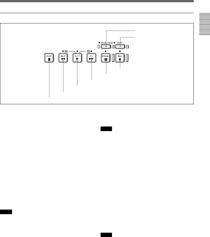
2 Tape transport control section
7 AUDIO DUB button/indicator
8 DUP button/indicator
6 REC button/indicator
5 PAUSE button/indicator
4 FF button/indicator
3 PLAY button/indicator
2 REW button/indicator
1 STOP button
1 STOP button
Press this button to stop the current tape transport operation.
2 REW (rewind) button/indicator
When you press this button, the indicator lights and the tape starts rewinding. During rewind, the picture does not appear on the monitor (you can see the picture as it is seen in the EE mode).
To locate a scene while monitoring the picture, hold this button down during rewind, playback or in the playback pause mode.
If you press the PLAY button while holding this button down during stop, the tape is rewound to its beginning and starts playback automatically (during rewind, the REW indicator lights and the PLAY indicator flashes). You can change the tape transport mode in FF/REW SPD on the VTR SET menu.
For details on the VTR SET menu, see “VTR SET menu” on page 65 (GB).
Notes
•If you set EE/PB SEL on the DISPLAY SET menu to PB, the EE pictures or EE sounds are not output while the tape rewinds.
•If you set FF/REW SPD on the VTR SET menu to SHUTTLEMAX, you can display the picture while the tape rewinds.
For details on the tape transport speed of the SHUTTLEMAX setting, see “FF/REW SPD” in the “VTR SET menu” on page 65 (GB).
3 PLAY button/indicator
When you press this button, the indicator lights and playback begins.
Notes
•If the unit is playing a part of the tape where the format has been changed between the DVCAM format and the DV format, or where the color system of the recorded signals has been changed between PAL and NTSC, the picture and sound are distorted.
•The unit can play back only tapes recorded in the DVCAM format or in the SP mode of the DV format.
4 FF (fast forward) button/indicator
When you press this button, the indicator lights and the tape is fast forwarded. During fast forward, the picture does not appear on the monitor (you can see the picture as it is seen in the EE mode).
To locate a scene while monitoring the picture, hold this button down during fast forward, playback or in the playback pause mode.
You can change the tape transport mode in FF/REW SPD on the VTR SET menu.
For details on the VTR SET menu, see “VTR SET menu” on page 65 (GB).
Notes
•If you set EE/PB SEL on the DISPLAY SET menu to PB, the EE pictures or EE sounds are not output while the tape is fast-forwarded.
(Continued)
Overview 1 Chapter
Chapter 1 Overview |
13 (GB) |

Overview 1 Chapter
Location and Function of Parts
•If you set FF/REW SPD on the VTR SET menu to SHUTTLEMAX, you can display the picture while fast-forwarding the tape.
For details on the tape transport speed of the SHUTTLEMAX setting, see “FF/REW SPD” in the “VTR SET menu” on page 65 (GB).
5 PAUSE button/indicator
When you press this button during recording, playing, or audio dubbing, the current operation goes into the pause mode. Pressing this button again resumes the operation. The indicator lights while the unit is in the pause mode.
6 REC (record) button/indicator
When you press the PLAY button while holding this button down, the PLAY and REC indicators light and recording starts.
When the unit is in the stop mode, you can check EE signals for an image, sound (channels 1 and 2) and time code by pressing this button. During this check, the REC indicator lights. To stop this operation, press the STOP button.
For details, see “EE/PB SEL” in the “DISPLAY SET menu” on page 62 (GB). For details on time codes, see “DSR-25 time codes” on page 46 (GB).
Note
The unit can record only in the DVCAM format or in the SP mode of the DV format.
7 AUDIO DUB (audio dubbing) button/indicator
Use this button to dub sounds. The indicator lights while sounds are being dubbed.
For details on audio dubbing, see “Audio Dubbing” on page 52 (GB).
When the unit is in the stop mode and the INPUT SELECT selector is set to other than DV, you can listen to the EE signal of the sound (channels 3 and 4) to be dubbed by pressing this button. During this operation, the indicator lights. To stop the operation, press the STOP button.
For details, see “EE/PB SEL” in the “DISPLAY SET menu” on page 62 (GB).
8 DUP (duplicate) button/indicator
Use to duplicate a tape, including the time code. During duplication, the indicator lights.
For details on the duplicate function, see “Duplication (generating a work tape with the same time code)” on page 47 (GB).
When the unit is in the stop mode and a DV signal is selected and input, you can check the EE signals for an image, sound and time code by pressing this button. During the check, the indicator lights. To stop this operation, press the STOP button.
For details, see “EE/PB SEL” in the “DISPLAY SET menu” on page 62 (GB). For details on time codes, see “DSR-25 time codes” on page 46 (GB).
14 (GB) |
Chapter 1 Overview |
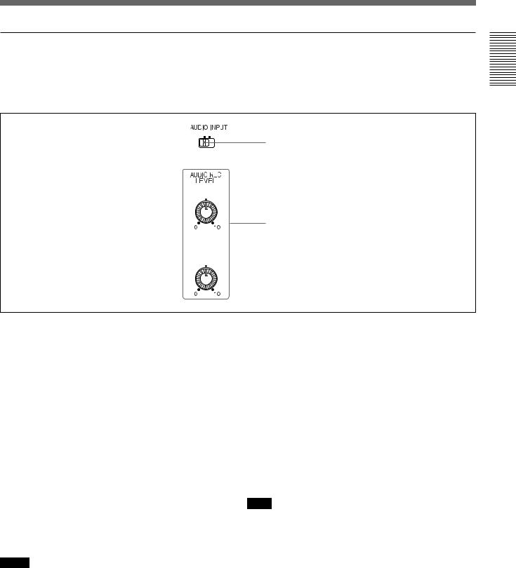
3 Audio control section
During normal recording, sounds are recorded onto channels 1 and 2; they cannot be recorded onto channels 3 and 4. During audio dubbing, sounds are dubbed onto channels 3 and 4.
FIX VAR
1 AUDIO INPUT switch
CH-1
(DUB CH-3)
2 AUDIO REC LEVEL control knobs
CH-2
(DUB CH-4)
Overview 1 Chapter
1 AUDIO INPUT (FIX/VAR) switch
Switches the audio recording level adjustment mode. FIX: With reference to the level set by the AUDIO
INPUT LEVEL selector on the rear panel, the unit records sounds with fixed gain. (Adjustment of the AUDIO REC LEVEL control knobs 2 is disabled.) At the maximum, a level that exceeds the reference level by 20 dB (set by the AUDIO INPUT LEVEL selector) is acceptable. For details, see the table below.
AUDIO INPUT LEVEL |
Acceptable level (max.) |
selector |
|
|
|
–10 |
+10 dBu |
|
|
–2 |
+18 dBu |
|
|
+4 |
+24 dBu |
|
|
VAR: Enables the AUDIO REC LEVEL control knobs 2.
Notes
•When DV signals are input to the unit, the sound recorded retains the signal level input, regardless of the setting of this switch.
•If you input a sound whose level exceeds the acceptable range, the sound recorded will be distorted.
2 AUDIO REC LEVEL control knobs (CH-1 (DUB CH-3), CH-2 (DUB CH-4) )
When intending to perform normal recording, by using these knobs, adjust the levels of the analog audio signals input to the unit (channel 1 and 2). When intending to perform audio dubbing, using these knobs, adjust the levels of channel 3 and 4.
These knobs are enabled only when the AUDIO INPUT (FIX/VAR) switch 1 is set to VAR.
To display the audio level meters on the LCD monitor, set the DISPLAY SELECT selector on the monitor display section to AUDIO (audio screen).
For details on the audio screen, see “Audio screen” on page 24 (GB).
Note
You cannot adjust the audio level of the DV signal.
Chapter 1 Overview |
15 (GB) |
Overview 1 Chapter
Location and Function of Parts
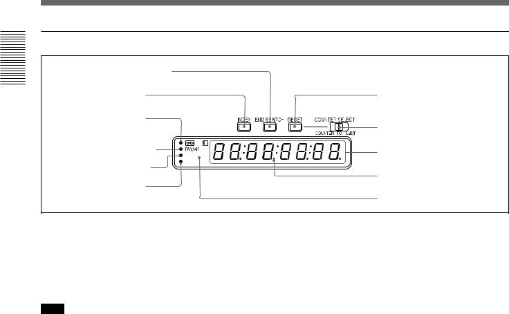
4 Display window
1 END SEARCH button |
|
|
2 INDEX button |
|
0 RESET button |
3 q (cassette) |
|
|
indicator |
|
9 COUNTER SELECT |
|
|
|
|
|
selector |
4 DVCAM indicator |
|
8 Time counter display |
|
NTSC |
|
|
|
|
5 NTSC indicator |
PAL |
|
|
Drop frame indicator |
|
|
|
|
6 PAL indicator |
|
|
|
|
7 Remote control detector |
1 END SEARCH button
When you press this button, the unit searches the tape and plays back the last five-second recorded picture. After playback, the unit turns to the stop mode. Use this function to record another image at the end of the last recorded portion or to check the image itself.
Note
If you use a cassette without cassette memory, the end search function does not work once you eject the cassette after you have recorded on the tape. If you use a cassette with cassette memory, the end search function works even if you have ejected the cassette one or more times. If there is a blank portion at the beginning or between recorded portions, the end search function may not work correctly.
2 INDEX button
Press this button during recording to mark an index. If you mark an index at the scene you want to search for, you can easily find the scene later.
For details on index, see “Recording Functions” on page 40 (GB).
3 q (cassette) indicator
Lights when a digital video cassette is loaded. Even if the unit is in the standby mode, the indicator lights as long as a cassette is inside of the unit. While a cassette is being ejected, the indicator flashes.
4 DVCAM indicator
Lights when the unit is playing back a tape recorded in the DVCAM format. When REC MODE on the VTR SET menu is set to DVCAM, this indicator also lights during recording or when the unit is in the EE mode.
For details on the VTR SET menu, see “VTR SET menu” on page 65 (GB).
5 NTSC indicator
Lights when:
•In the EE mode or during recording and the NTSC/ PAL select switch is set to NTSC.
•NTSC formatted video signals are input to the DV jack.
•a tape that has NTSC formatted video signals is being played back.
6 PAL indicator
Lights when:
•In the EE mode or during recording and the NTSC/ PAL select switch is set to PAL.
•PAL formatted video signals are input to the DV jack.
•a tape that has PAL formatted video signals is being played back.
7 Remote control detector
8 Time counter display
Displays time data (count value of the counter / time code / user bits), the self-diagnostics code numbers (page 75 (GB)), or the alarm messages (“Err” (page 72 (GB))).
When the count value of the counter is negative, “–” appears as the first digit (leftmost digit). When that value is positive, the first digit is blank.
When the format of the displayed time code is drop frame mode, the drop frame indicator, located between minutes and seconds, lights.
The user bits are displayed with periods (.) after each digit.
16 (GB) |
Chapter 1 Overview |

Notes
•In the playback mode, if the tape has a portion where recorded signals are not continuous:
–The count value of the counter may not advance correctly from that portion.
–The displayed value of the time code or user bits may be temporarily inaccurate.
•When this unit plays back a part of the tape where the recorded color system has been changed between PAL and NTSC, the displayed value may be inaccurate.
•When this unit plays back a part of the tape where the recording format has been changed between DVCAM and DV, the displayed value may be inaccurate.
•The counter operates on a ±12-hour cycle. You cannot make the counter operate on a 24-hour cycle.
•The count value of the counter consists of seven digits. The leftmost digit is not displayed. (i.e.; If the actual count value is “11:22:11:22,” the displayed value will be “1:22:11:22.” ) However, the unit recognizes that the hours value is 11.
9 COUNTER SELECT selector
Selects the time data to be indicated on the time counter display. Selected time data is also displayed on the LCD monitor or on the counter display of a monitor connected to the S VIDEO or VIDEO connectors in OUTPUT.
COUNTER: Count value of the counter (seven digits). The value is displayed on a ±12-hour cycle.
TC: Time code U-BIT: User bits
Note
The count value of the counter of this unit is determined by calculation based on the time code, that is, simple approximation. Therefore, in cases such as the following, the value may be inaccurate.
•There is a portion where the time code is not continuous on the tape you are using.
•The time code in both the drop frame mode and the non-drop frame mode are recorded on the tape you are using (For NTSC only).
•There is a blank portion between recorded portions on the tape you are using.
•A tape recorded using the PAL color system is being used in this unit when the NTSC/PAL select switch is set to NTSC.
•A tape recorded using the NTSC color system is being used in this unit when the NTSC/PAL select
switch is set to PAL.
•TC RUN on the TC/UB SET menu is set to FREE RUN.
0 RESET (counter reset) button
When the COUNTER SELECT selector 9 is set to COUNTER, pressing this button resets the value indicated on the time counter display to 0:00:00:00 (0H00M00S00F).
Notes
•This button cannot reset the value of the time code or user bits.
•To reset the value of the time code or user bits, use TC PRESET or UB PRESET on the TC/UB SET menu.
Overview 1 Chapter
Chapter 1 Overview |
17 (GB) |
Overview 1 Chapter
Location and Function of Parts
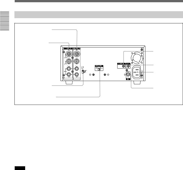
Rear Panel
1 OUTPUT connectors
2 INPUT connectors |
|
|
8 LANC jack |
|
7 CONTROL S IN |
|
jack |
|
6 AC IN connector |
3 AUDIO INPUT LEVEL |
5 DV jack |
selector |
4 NTSC/PAL select switch
1 OUTPUT connectors
Used to output analog video and audio signals. To connect a device equipped with S-video input, use the S VIDEO connector on the unit.
When the CHARACTER DISPLAY switch is set to ON, data items, such as time data, menus, and warnings, are superimposed on a monitor connected to the S VIDEO and the VIDEO connectors.
For details on the superimposed data items, see “Displaying Various Data” on page 23 (GB).
The audio output level of this unit is 2 Vrms (full bit). When the AUDIO OUTPUT SELECT selector is set to MIX, that drops to 50 % (–6 dB).
Notes
•Data items superimposed on a monitor connected to these connectors are the same as those superimposed on the LCD monitor.
You cannot make two monitors display different data items individually.
•If you want to output video signals without text data, carry out the following operations.
–Set the CHARACTER DISPLAY switch on the front panel to OFF.
–Set TITLE DISP and LABEL DISP on the CM SET menu to OFF.
–Depending on the displayed items, press the DATA CODE or SEARCH SELECT button on the Remote Commander to clear the text data on the monitor screen.
For details on text data, see “Displaying Various Data” on page 23 (GB).
For details on the CM SET menu, see “CM SET menu” on page 58 (GB).
•In the EE mode (when the input signal is output as an analog signal) or during recording, the subcarrier of the color signal is not synchronized with the horizontal sync signal. The color of the picture or the horizontal sync signal may be distorted depending on the type of monitor connected to the unit.
•Sync and burst signals of the EE pictures output via these connectors are not synchronized.
•If DV input has been selected, color and luminance may be distorted in the EE mode, depending on the monitor.
•The unit only can accept standard video signals.
If you input the types of video signals shown below, recorded picture, sound and the EE picture output via these connectors may be distorted.
–Signals from some home game machines
–Blue background screen or gray background screen from a consumer VCR
–Pictures played at a speed other than normal by a VCR that does not have the TBC (Time Base Corrector)
–Video signals in which the sync signals are distorted
–Signals from a defective cassette (tape or recording condition is bad) played by an analog VCR that does not have TBC
18 (GB) |
Chapter 1 Overview |

2 INPUT connectors
Use to input analog video and audio signals. To connect a device equipped with S-video output, use the S VIDEO connector on the unit. During normal recording, sounds are recorded onto channels 1 and 2; they cannot be recorded onto channels 3 and 4. During audio dubbing, sounds are dubbed onto channels 3 and 4.
Notes
•In the audio dubbing mode, the AUDIO (CH-1/3) jack functions as channel 3 input and the AUDIO (CH-2/4) jack functions as channel 4 input.
•To input balanced audio signals via AUDIO jacks, use a conversion cable as shown below. (The COLD
side is open.)
For details on conversion cables, refer to the instruction manual of the devices you use.
GND |
HOT
COLD ×
×
3 AUDIO INPUT LEVEL (–10/–2/+4) selector
Selects one from among –10 dB, –2 dB, or +4 dB according to the audio level of the signal input via the AUDIO jacks in INPUT.
Notes
•If this selector setting is not appropriate, clipping distortion or noise may occur.
•For more information on the setting of this selector, see “When you set the AUDIO INPUT LEVEL selector” on page 71 (GB).
4 NTSC/PAL select switch
Used to switch the color system of signals that will be recorded on the unit when you use analog input. Before inputting NTSC or PAL formatted analog video signals, set this switch to the appropriate position according to the color system of the signal input.
Notes
•If the color system of the input signals is different from that of the switch setting, picture will be blanked.
•While signals are input to the DV jack or during playback, this switch setting is invalid. The unit detects the color system of the signals automatically.
•When this switch is set to PAL, the unit works as a PAL model. Therefore, the time code generated by the unit during recording in the DVCAM format is that of the non-drop frame mode. Even if an NTSC formatted signal is input to the DV jack, the time code generated by the unit is non-drop frame mode as long as the switch is set to PAL, regardless of the TC FORMAT setting on the TC/UB SET menu. If you intend to set the unit to generate the time code in the drop frame mode, set this switch to NTSC.
•The color system of the signals output from the unit is the one recorded on the tape being played back. The unit cannot convert the color system of signals of one system into that of the other. (For example: converting NTSC formatted signals into PAL formatted signals is not possible) Therefore, to view or record the signal output from the unit, you need a device compatible with the color system of the signals output from the unit.
•When the color system of playback signals is different from the one last used on the unit, playback picture and sound will be distorted and time code will be discontinuous for a short time at the beginning of the playback.
•If you play back a tape with both NTSC and PAL color system recordings, the following limitations are applied.
–At the point where the color system of the recorded signals changes, the picture may be distorted or audio noise may be output.
–The tape transport control buttons may be disabled until the tape running is stabilized.
•Do not change this switch setting during recording.
•At the beginning or end of playback, if the color system of signals recorded on the tape used is different from this switch setting, pictures and sounds output from the unit, and pictures on the LCD monitor, etc., may be distorted.
5 DV jack (4-pin)
Used to input/output the digital signal that complies with the i.LINK standard (Recommended cable: VMCIL4415 (A), VMC-IL4615 (A)). Use when a device connected to the unit has a DV jack. If you connect the unit and another device using DV jacks, you can minimize deterioration of picture quality during recording, dubbing, or capturing still pictures, all by means of digital signal processing. For details, refer to the instruction manual of the external device.
(Continued)
Overview 1 Chapter
Chapter 1 Overview |
19 (GB) |

Overview 1 Chapter
Location and Function of Parts
Notes
•If video signals have been input to the DV jack and you output these video signals to the S VIDEO or VIDEO connectors, the sync and burst of the corresponding EE pictures are not synchronized.
•i.LINK and the i.LINK logo “ ” are trademarks and indicate that this product is in agreement with IEEE 1394-1995 specifications and their revisions.
•This jack can accept only DV signals.
•If the unit is connected to a device equipped with a 6- pin DV jack, when you intend to disconnect or reconnect the DV cable, turn off the device and pull out the plug of its power cord from the AC outlet beforehand. If you connect or disconnect the DV cable while the device is connected to the AC outlet, high-voltage current (8 to 40 V) is output from the DV jack of the device to this unit, which may cause a malfunction.
•When connecting a device that has a 6-pin DV jack to this unit, first, connect the plug of the cable to the 6- pin DV jack.
6 AC IN connector
Connects to an AC outlet using the supplied power cord.
Even if the unit is in the standby mode, it consumes power. To turn the unit off completely, pull the plug out from the AC outlet.
7 CONTROL S IN jack (stereo minijack)
Connects to the Remote Control Unit (DSRM-20, not supplied) for controlling this unit.
Note
When using the Remote Control Unit (DSRM-20, not supplied), set COMMANDER on the OTHERS menu to CONTROL S.
8 LANC jack
Use when controlling the tape transport operation of the unit using a device that has a LANC1) jack.
Notes
•The LANC jack on the unit has only LANC-S functions. The unit has no LANC-M functions. A device that is set to LANC-S mode cannot be connected to this unit. Either this, the unit or the other device may not operate properly.
•If the device that you connect to this unit has a SHUTTLE A/B switching function and a LANC-M function, set the device to the SHUTTLE B mode.
•The LANC connection transmits signals such as control signals, time code, time counter data, and status data.
•Jacks labeled CONTROL L have the same function as LANC jacks.
•When using this unit as a player, set the LANC mode on the recorder to M. A device that does not have an M / S switching function cannot be used to control this unit.
.........................................................................................................................................................................................................
1)LANC (Local Application Control bus system): Bidirectional interface to control a consumer VCR
20 (GB) |
Chapter 1 Overview |
Supplied Remote Commander
1 EJECT button
2SEARCH SELECT buttons
3Buttons for playing at various speeds
EJECT |
|
|
|
× |
× |
× |
× |
qs 1 switch
qa DATA CODE button
0 INDEX WRITE button
4 PAUSE button |
9 REC buttons |
|
5 REW button 


 8 STOP button
|
VTR RMT-DS5 |
6 PLAY button |
7 FF button |
Overview 1 Chapter
1 EJECT button
Note
When there is no cassette inside the unit, you cannot open/close the cassette compartment, even if you press this button.
In this case, press the EJECT button on the front panel of the unit instead.
2 SEARCH SELECT buttons
Press these buttons to search for scenes using the search function.
For details on the search function, see “Searching using the search function” on page 33 (GB).
3 Buttons for playing at various speeds
You can play back a tape at normal speed or at a speed other than normal with these buttons.
For details, see “Playing at various speeds” on page 33 (GB).
4 PAUSE button
5 REW (rewind) button
6 PLAY button
7 FF (fast forward) button
8 STOP button
9 REC (record) buttons
When you press both these buttons at the same time, the REC indicator and PLAY indicator on the front panel light and recording begins.
0 INDEX WRITE button
Press this button during recording to mark an index.
For details on an index, see “Marking an index” on page 40 (GB).
(Continued)
Chapter 1 Overview |
21 (GB) |
Overview 1 Chapter
Location and Function of Parts
qa DATA CODE button
Press this button to display the data codes (recording date/time, camera data).
For details on data codes, see “Displaying information (data codes) recorded on a tape” on page 32 (GB).
qs 1 (on/standby) switch
Notes
•The command mode of the supplied Remote commander is set to VTR4. You cannot change this setting.
•Set COMMANDER on the OTHERS menu to WIRELESS to enable the Remote Commander to control the unit.
•In addition to the Remote Commander supplied with the unit, the unit accepts signals from any Sony Remote Commander whose command mode is set to VTR4. If you want to disable the control from any Remote Commander, set COMMANDER on the OTHERS menu to CONTROL S.
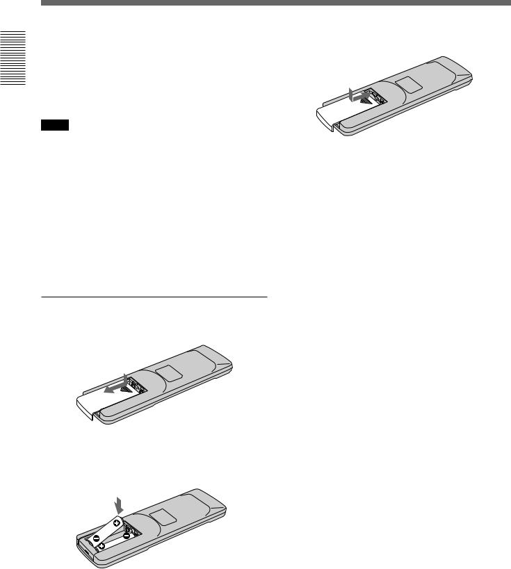
Battery installation
1 Push and slide the lid to open.
2 Install two size AA (R6) batteries (supplied) with the correct polarity.
Be sure to install the battery
3 Replace the lid.
Notes on batteries
•Make sure that the battery orientation is correct when inserting batteries.
•Do not mix an old battery with a new one, or mix different types of batteries.
•If you do not intend to use the Remote Commander for a long time, remove the batteries to avoid damage from battery leakage. If the batteries have leaked, remove them, wipe the battery compartment dry and replace the batteries with new ones.
To remove the batteries
Remove the lid as step 1 and take out the batteries.
22 (GB) |
Chapter 1 Overview |
Displaying Various Data
The unit can display various superimposed data items on the built-in LCD monitor or on a monitor connected to the S VIDEO or VIDEO connectors in OUTPUT. To display various data items on the LCD monitor, set the CHARACTER DISPLAY (LCD) selector to ON or ON (BLACK BACK).
To display various data items on an external monitor, set the CHARACTER DISPLAY switch to ON.
You can select data items to be displayed using the DISPLAY SELECT selector.
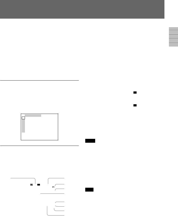
Menu screen
To display the menu screen, set the DISPLAY SELECT selector to MENU. You can change or confirm the menu item settings on this screen.
For details on the menu, see “Chapter 5 Adjusting and Setting Through Menus” on page 54 (GB).
TC ⁄ UB SET
TC TC PRESET
CM UB PRESET
DISP DV IN TC
V TC MAKE
A TC RUN
VTR TC FORMAT
ETC
Data screen
To display the data screen, set the DISPLAY SELECT selector to DATA. You can confirm important information for recording or playback, such as time code or remaining tape time, on this screen.
2 |
|
|
3 |
|
1 |
|
|
|
4 |
|
|
N TC 00:12:34:12 |
||
|
|
|||
|
|
|
122min |
5,6 |
|
|
|
PHOTO –10 |
|
|
|
|
SEARCH |
7 |
|
|
|
Z |
|
|
|
% |
|
|
|
|
|
DEW |
|
|
|
|
DETECTED |
|
|
|
|
DVCAM |
8 |
|
|
|
NS 48K |
9 |
|
|
|
DV I N |
|
|
|
|
|
|
|
|
|
|
q; |
|
|
|
|
|
|
|
|
|
qa |
1 Cassette memory indicator
This item is shown when a cassette with cassette memory has been loaded. If the cassette is ejected while data is being written on the cassette memory, the indicator flashes.
2 Tape transport mode indicator
Displays the tape transport mode.
3 Time counter (time code/user bits/count value of the counter) indicator
Displays the count value of the counter, time code, or user bits. By setting the COUNTER SELECT selector on the front panel, you can select the item to be displayed.
When the time code is displayed, TC appears to its left. In the drop frame mode, a period is displayed between the minutes and seconds. (Example: 00:12.58:00)
When the user bits are displayed, UB appears to their left.
When the count value of the counter is negative, “–” appears as the first digit (leftmost digit). When that value is positive, the first digit is blank.
The count value of the counter consists of seven digits. If the self-diagnostic function is enabled, diagnostics code numbers are displayed.
Notes
•The counter operates on a ±12-hour cycle. You cannot make the counter operate on a 24-hour cycle.
•The count value of the counter consists of seven digits. The leftmost digit is not displayed. (i.e.; If the actual count value is “11:22:11:22,” the displayed value will be “1:22:11:22.” ) However, the unit recognizes that the hours value is 11.
4 Remaining tape time indicator
Displays the remaining tape time.
Note
When you insert a cassette in which the tape has been rewound to the beginning, this indicator will not show the remaining tape time. The remaining tape time is displayed after the tape runs for a while.
5 Search indicator
Displays the search mode when you search for scenes using the Remote Commander or the DSRM-20 (not supplied).
For details on the search function, see “Searching using the search function” on page 33 (GB).
(Continued)
Overview 1 Chapter
Chapter 1 Overview |
23 (GB) |

Overview 1 Chapter
Displaying Various Data
6 Index indicator
Displays INDEX MARK when an index has been marked.
7 Caution indicator
Displays a caution.
For details on cautions, see “Alarm Messages” on page 72 (GB).
8 DVCAM/DV indicator
In the EE or recording mode, displays the recording format selected in REC MODE on the VTR SET menu. During playback, displays the recording format of the picture.
9 Audio mode indicator
In the EE or recording mode, displays the audio mode selected in AUDIO MODE on the AUDIO SET menu. During playback or audio dubbing, displays the audio mode recorded on the tape. When you input a signal to the DV jack, displays the audio mode of that signal.
0 Input signal indicator
Displays the INPUT SELECT selector setting.
qa NS (Non standard) audio mode indicator
This item is shown when a tape recorded in the unlock audio mode is played back or when an unlock mode signal has been input to the DV jack. In EE mode, when REC MODE in the VTR SET menu is set to DV SP, this item is always shown.
For details on the unlock mode, see “Compatibility of DVCAM and DV Format” on page 76 (GB).
Audio screen
To display the audio screen, set the DISPLAY SELECT selector to AUDIO. You can confirm or adjust the audio levels on this screen. The display of this screen changes depending on the audio mode and the setting of the AUDIO OUTPUT SELECT selector. The unit detects the audio mode as follows:
In the playback mode: Detects the audio mode recorded on the tape.
In the recording/EE mode: Detects the selected audio mode in AUDIO MODE on the AUDIO SET menu.
When the INPUT SELECT selector is set to DV and a DV signal is being input: Detects the audio mode of the signals being input. (The setting of AUDIO MODE on the AUDIO SET menu becomes invalid.)
Audio mode: 48 kHz (2-channel, 16 bits)
–∞ 40 30 |
20 10 |
0 dB |
· · · |
· · |
· |
CH1 ||||||||||||||||||·|··· ·
CH2 |||||||||||||||||·|···· ·
(The levels of two channels, channels 1 and 2, are displayed.)
Audio mode: 32 kHz (4-channel, 12 bits)
(a)When the AUDIO OUTPUT SELECT selector is set to CH-1/2 or CH-3/4
|
–∞ 40 30 |
20 10 |
0 dB |
CH1 |
· · · |
· · |
· |
||||||||||||||||||·|··· · |
|||
CH2 |
|||||||||||||||||·|···· · |
||
CH3 |
| |
|
· |
CH4 |
| |
|
· |
(The levels of four channels, channels 1 to 4, are displayed. During playback, if the sounds are recorded onto channels 3 and 4, their levels meters will fluctuate. However, during normal recording, you cannot record sounds onto the channels 3 and 4.)
(b)When the AUDIO OUTPUT SELECT selector is set to MIX
-∞ 40 30 |
20 |
10 |
0 dB |
· · · |
· |
· |
· |
CH1 ⁄ 3 ||||||||||||||||||·|···
CH2 ⁄ 4 |||||||||||||||||·|····
(The mixed level of channels 1 and 3 is displayed on CH1/3; that of channels 2 and 4 is displayed on CH2/4. The signal level of each channel is dropped to 50% (–6 dB).)
24 (GB) |
Chapter 1 Overview |

When the unit is in the audio dubbing mode and the AUDIO OUTPUT SELECT selector is set to CH-1/2 or CH-3/4
|
–∞ 40 30 |
20 10 |
0 dB |
CH1 |
· · · |
· · |
· |
||||||||||||||||||·|··· · |
|||
CH2 |
|||||||||||||||||·|···· · |
||
CH3 |
||||||||||||||||||||||| | |
||
CH4 |
|||||||||||||·|········ · |
||
(The levels of playback sound are displayed on CH1 and CH2. The levels of input sound to be dubbed are displayed on CH3 and CH4. When the AUDIO OUTPUT SELECT selector is set to MIX, the mixed level of the pair of channels 1 and 3 and that of channels 2 and 4 is displayed. The signal level of each channel is dropped to 50 %
(–6 dB). In this case, the meters are as illustrated in (b) above. To check only the sound to be dubbed before dubbing, press the DUB button while the unit is in the stop mode. Then, only the levels meters of the channels used to dub (channel 3 and 4) fluctuate.)
Note
In the EE, recording, or audio dubbing (only the channels used to dub) mode, if the input levels exceed 0 dB, the portions of the meters that exceed 0 dB turn to red. (Only when the audio mode is 32 kHz (4- channel, 12 bits) and the AUDIO OUTPUT SELECT selector is set to MIX, that portions of the levels meters do not turn to red even if the meters exceed 0 dB.) During playback or while DV signals are input, the levels meters do not turn to red.
Overview 1 Chapter
Chapter 1 Overview |
25 (GB) |
Notes on Video Cassettes
Chapter2
Recording and Playback 2 Chapter
Playback and
Recording
Notes on Video Cassettes
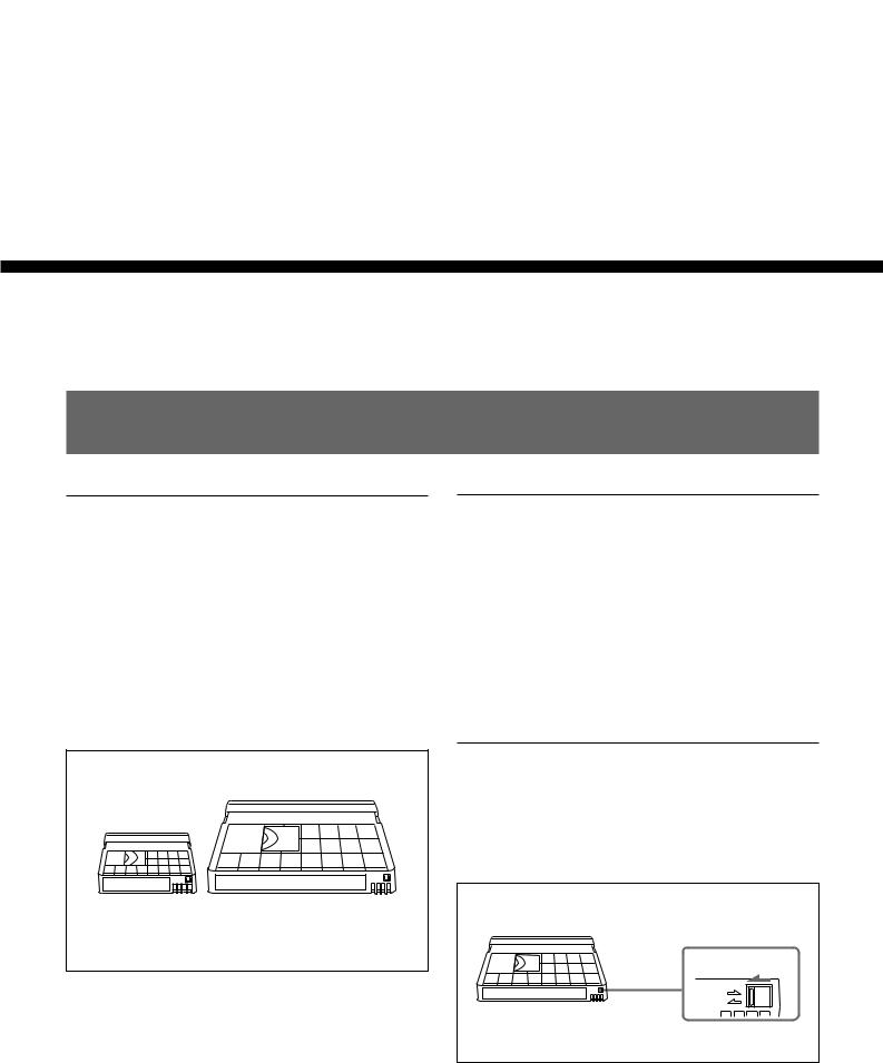
Usable cassettes
Use Standard-DVCAM cassettes or Mini-DVCAM cassettes with this unit. The PDV-184 can record programs for 184 minutes and the PDVM-40 can record for 40 minutes (DVCAM format).
You can get the highest quality pictures with this digital videocassette recorder using DVCAM cassettes. Using other cassettes does not ensure sufficient reliability. We recommend using DVCAM cassettes so that you can record your one-time events in the highest quality.
Mini DVCAM cassette |
DVCAM cassette |
Cassette memory
Cassette memory is an optional feature that is mounted on some Standard DVCAM cassettes and Mini DVCAM cassettes. When you record a program, the recording date and time, and the programs’ position on the tape are stored in the cassette memory so that you can quickly locate the program later on. 


 on a cassette indicates that you can use the cassettes to store up to 16 kbits of data. On this unit, you can use cassettes on which up to 16 kbits of data can be stored.
To save a recording
To prevent accidental erasure of a recording, slide in the REC/SAVE switch on the cassette so that the red portion becomes visible. To record on a tape, slide out the switch so that the red portion is hidden.
REC/SAVE switch |
Set to SAVE. |
REC |
SAVE |
26 (GB) |
Chapter 2 Playback and Recording |
 Loading...