


11-DSR
3-065-956-13(1)
Digital
Videocassette
Recorder
Operating Instructions |
|
GB |
|
|
|
||
|
|
|
|
Mode d’emploi |
|
|
FR |
DSR-11
2000 Sony Corporation

WARNING
To prevent fire or shock hazard, do not expose the unit to rain or moisture.
This symbol is intended to alert the user to the presence of uninsulated “dangerous voltage” within the product’s enclosure that may be of sufficient magnitude to constitute a risk of electric shock to persons.
This symbol is intended to alert the user to the presence of important operating and maintenance (servicing) instructions in the literature accompanying the appliance.
The AC adaptor must be changed only at qualified service shop.
The nameplate of the AC adaptor is located on its bottom.
For customers in Europe
This product with the CE marking complies with both the EMC Directive (89/336/EEC) and the Low Voltage Directive (73/23/EEC) issued by the Commission of the European Community.
Compliance with these directives implies conformity to the following European standards:
•EN60065: Product Safety (supplied AC adaptor)
•EN55103-1: Electromagnetic Interference (Emission)
•EN55103-2: Electromagnetic Susceptibility (Immunity) This product is intended for use in the following Electromagnetic Environment(s):
E1 (residential), E2 (commercial and light industrial), E3 (urban outdoors) and E4 (controlled EMC environment, ex. TV studio).
For the customers in the Netherlands
Voor de klanten in Nederland
Bij dit product zijn batterijen geleverd. Wanneer deze leeg zijn, moet u ze niet weggooien maar inleveren als KCA.
Owner’s record
The model number is located at the rear and front of the unit and the serial number on the rear. Record the serial number in the space provided below. Refer to these numbers whenever you call upon your Sony dealer regarding this product.
Model No. DSR-11 Serial No. ______________________
For customers in the U.S.A.
If you have any questions about this product, you may call: Sony’s Business Information Center (BIC) at 1-800- 686-SONY (7669)
or Write to: Sony Customer Information Services Center 6900-29 Daniels Parkway, PMB 330 Fort Myers, Florida 33912
Declaration of Conformity
Trade Name: |
SONY |
Model: |
DSR-11 |
Responsible Party: |
Sony Electronics Inc. |
Address: |
1 Sony Drive, Park Ridge, |
|
NJ 07656 U.S.A |
Telephone Number: |
201-930-6972 |
This device complies with Part 15 of the FCC Rules. Operation is subject to the following two conditions: (1) This device may not cause harmful interference, and (2) this device must accept any interference received, including interference that may cause undesired operation.
2 (GB)
CAUTION
You are cautioned that any changes or modifications not expressly approved in this manual could void your authority to operate this equipment.
Note
This equipment has been tested and found to comply with the limits for a Class B digital device, pursuant to Part 15 of the FCC Rules. These limits are designed to provide reasonable protection against harmful interference in a residential installation. This equipment generates, uses, and can radiate radio frequency energy and, if not installed and used in accordance with the instructions, may cause harmful interference to radio communications. However, there is no guarantee that interference will not occur in a particular installation. If this equipment does cause harmful interference to radio or television reception, which can be determined by turning the equipment off and on, the user is encouraged to try to correct the interference by one or more of the following measures:
•Reorient or relocate the receiving antenna.
•Increase the separation between the equipment and receiver.
•Connect the equipment into an outlet on a circuit different from that to which the receiver is connected.
•Consult the dealer or an experienced radio/TV technician for help.
For customers in the U.S.A. and CANADA
CAUTION
TO PREVENT ELECTRIC SHOCK, MATCH WIDE BLADE OF PLUG TO WIDE SLOT, FULLY INSERT.
Caution
Television programs, films, video tapes and other materials may be copyrighted. Unauthorized recording of such material may be contrary to the provisions of the copyright laws. Also, use of this recorder with cable television transmission may require authorization from the cable television transmission and/or program owner.
Precautions
•Do not damage the power cord and AC adaptor.
•Use only the supplied power cord and supplied AC adaptor.
•Do not use the unit in an environment that is subject to excessive soot, steam, humidity or dust.
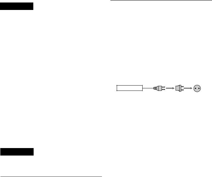
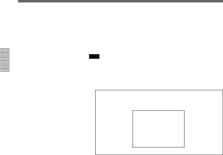
You can use this equipment in any country or area with the AC power adaptor supplied with this unit within 100 V to 240 V AC, 50/60 Hz.
Use a commercially available AC plug adaptor [a], if necessary, depending on the design of the wall outlet
[b].
AC-SU1
[a] [b]
The AC adaptor is not intended to be serviced. Should the product cease to function in its intended manner, it should be returned to the manufacturer or be discarded.
On installing
The unit is equipped with ventilation holes on the rear. Do not block or place anything near these holes, or internal heat build-up may occur, causing damage to the unit.
On repacking and shipping
Save the original shipping carton and packing material; they will come in handy if you ever have to ship your unit. For maximum protection, repack your unit as it was originally packed at the factory, and take care not to impart violent shocks in transit.
3 (GB)

TableTableof CofntentsContents
Chapter1
Overview
Chapter 2
Features .................................................................... |
6 (GB) |
|
DVCAM Format ......................................................... |
6 |
(GB) |
Other Features ............................................................ |
7 |
(GB) |
Location and Function of Parts .............................. |
8 (GB) |
|
Front Panel ................................................................. |
8 |
(GB) |
Rear Panel ................................................................ |
11 |
(GB) |
Supplied Remote Commander ................................. |
13 |
(GB) |
Playback and
Recording
Chapter 3
Notes on Video Cassettes ..................................... |
15 (GB) |
Preparations ........................................................... |
17 (GB) |
Power Preparations ................................................... |
17 (GB) |
Inserting/Ejecting Cassettes ..................................... |
17 (GB) |
Notes on Recording/Playback .................................. |
19 (GB) |
Playback .................................................................. |
20 (GB) |
Connections for Playback ......................................... |
20 (GB) |
Settings for Playback ................................................ |
23 (GB) |
Playback Procedure .................................................. |
24 (GB) |
Playback Functions .................................................. |
25 (GB) |
Recording ............................................................... |
34 (GB) |
Connections for Recording ....................................... |
34 (GB) |
Settings for Recording .............................................. |
37 (GB) |
Recording Procedure ................................................ |
39 (GB) |
Installing the Unit Vertically .................................. |
40 (GB) |
Adjusting and
Setting Through
Menus
Operating the Menus ............................................. |
41 (GB) |
Menu Organization ................................................... |
42 (GB) |
Menu Contents ......................................................... |
43 (GB) |
4 (GB) |
Table of Contents |

Chapter 4
Maintenance
Troubleshooting ..................................................... |
50 (GB) |
Alarm Messages ..................................................... |
51 (GB) |
Notes on Use .......................................................... |
52 (GB) |
Appendix
Compatibility of DVCAM and DV Format ............. |
55 (GB) |
Specifications ......................................................... |
58 (GB) |
Glossary .................................................................. |
60 (GB) |
Index ........................................................................ |
61 (GB) |
GB
English
Table of Contents |
5 (GB) |

Features
Overview 1 Chapter
Chapter1
Overview
Features
The DSR-11 is a 1/4-inch digital video cassette recorder that uses the DVCAMTM digital recording format. This system achieves stable, superb picture quality by digitally processing video signals that are separated into color difference signals and luminance signals (component video).
With a compact, lightweight and space-saving case, the unit can be installed vertically and is equipped with an analog interface as well as a digital interface enabling connection to a digital device such as a computer.
The DSR-11’s main features are described below.
DVCAM Format
DVCAM is based on the consumer DV format, which uses the 4:1:1 component digital format (NTSC) or the 4:2:0 format (PAL), and provides a 1/4-inch digital recording format for professional use.
High picture quality, high stability
Video signals are separated into color difference signals and luminance signals, which are encoded and compressed to one-fifth size before being recorded to ensure stable and superb picture quality.
Because the recording is digital, multi-generation digital dubbing can be performed with virtually no deterioration of quality.
Wide track pitch
The recording track pitch is 15 µm, fully 50 percent wider than the DV format’s 10-µm track pitch. Thanks to this feature, the DVCAM format sufficiently meets the reliability and precision requirements of professional editing.
High-quality PCM digital audio
PCM recording makes for a wide dynamic range and a high signal-to-noise ratio, thereby enhancing sound quality.
There are two recording modes: 2-channel mode (48kHz sampling and 16-bit linear code), which offers sound quality equivalent to the DAT (Digital Audio Tape) format, or 4-channel mode (32-kHz sampling and 12-bit nonlinear code).
DV format compatibility
A DV cassette recorded on a DV-format VCR can be played back on the unit (SP mode only). The unit can also record in DV format (SP mode only). (Recording/ playing back an image in LP mode is not available.)
6 (GB) |
Chapter 1 Overview |

NTSC/PAL systems compatible
The unit is compatible with NTSC and PAL systems. When inputting the signals to the DV IN/OUT connector or playing back a tape, the color system of signals is detected automatically. The color system select switch on the unit allows input of analog video signals in either color system. This compatibility allows you to record (download) or play back (upload) both NTSC and PAL formatted signals with your VCR, computer, or other equipment.
However, the unit cannot convert the color system of the signals.
Choice of two cassette sizes
The unit can use both standard-size and mini-size DVCAM or DV cassettes.
•According to cassette size, the position of the reel drive plate changes automatically.
•The maximum recording/playback times are 184 minutes for standard size cassettes and 40 minutes for mini-size cassettes (DVCAM format).
Remote control
The unit can be operated by remote control from a CONTROL-S system remote control unit, the DSRM20 (not supplied).
High-speed search function
When you use an editing controller or the optional remote control unit (DSRM-20), the unit has a picture search function that allows you to view color picture at playback speeds up to 14 times (NTSC) or up to 17 times (PAL) normal speed in forward and reverse directions. You can also search frame-by-frame in jog mode.
You can also hear playback audio.
Digital slow playback
The unit has a frame memory function that allows smooth, slow playback. This is available only at +1/3- time speed and –1/3-time speed.
Jog audio function
If you use the optional remote control unit DSRM-20, audio can be monitored at various playback speeds when in jog mode.
Other Features
Compact and can be installed vertically
The unit is compact and can be installed vertically. With non-linear editing system, you can save space by installing it vertically beside your computer.
Menu system for functionality and operation settings
The unit provides a menu system to make its various functions easier to use and set up.
Superimposition function
Time code, operation mode indications, menus, error messages, and other text data can be superimposed and output in analog video signals.
Easy maintenance functions
•Self-diagnostics/alarm functions: The system automatically detects an invalid operation, an invalid connection or a malfunction, and outputs a description, a cause and a recovery method as a message superimposed on analog video signals.
•Digital hours meter: A digital hours meter counts four types of time data—operating time, drum rotation time, tape running time, and tape threading/ unthreading. The digital hours data is displayed in the menu.
........................................................................................
 ,
,  ,
, 

 and
and 
 are trademarks of Sony Corporation.
Overview 1 Chapter
Chapter 1 Overview |
7 (GB) |
LocationLocationand FuandctionFunctionof Parts of Parts
Overview 1 Chapter
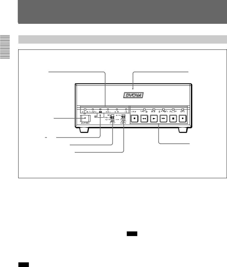
Front Panel
2Indicators
(see page 10 (GB))
5ON/STANDBY switch
4 Remote sensor
3 INPUT SELECT selector
2 REMOTE CONTROL switch
1 Cassette lid
1Tape transport control section (see page 9 (GB))
1 Cassette lid
To insert/eject a cassette, open the lid.
For details of usable cassettes, see “Notes on Video Cassettes” on page 15 (GB).
2 REMOTE CONTROL switch
Selects whether the unit is operated from the Remote Commander or from an optional remote control unit.
WIRELESS: The unit is operated from the Remote Commander.
CONTROL S: The unit is operated from a remote control unit (the DSRM-20, not supplied), connected to the CONTROL S jack on the rear panel.
Note
You can operate this unit from its front panel regardless of this switch setting.
3 INPUT SELECT selector
You can select DV, S VIDEO, or VIDEO to input the signals.
DV: Signal input from the DV IN/OUT connector
S VIDEO: Signal input from the S VIDEO connector on INPUT jacks
VIDEO: Signal input from the VIDEO jack on INPUT jacks
Note
Do not change the selector setting during recording. Otherwise, noise is output to the picture and sound and that portion will not be recorded properly.
4 Remote sensor
5 ON/STANDBY switch
8 (GB) |
Chapter 1 Overview |
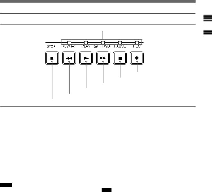
1 Tape transport control section
1 Tape transport indicators
2 REC button
3 PAUSE button
4 F FWD button
5 PLAY button
6 REW button
7 STOP button
1 Tape transport indicators
2 REC (record) button
When you press the PLAY button while holding down this button, the indicator lights and recording begins. To set the unit to recording pause mode, press the PAUSE and PLAY buttons while holding down this button. If you press only this button when the unit is in the stop mode and the DV IN TC on the OTHERS menu is set to EXTERNAL, the REC indicator lights and you can also check the EE signals for time code. After checking them, press the STOP button.
For details on the OTHERS menu, see “OTHERS menu” on page 49 (GB).
Notes
•The unit cannot record in the LP mode of the consumer DV format. Only recording in the SP mode is available.
•To set the unit to recording pause mode with the remote control unit (DSRM-20, not supplied), press the PAUSE button while holding down the PLAY button to set the unit to the playback pause mode, then press the REC button on the DSRM-20.
3 PAUSE button
Press this button to set the unit to pause mode while recording or playing. Pressing this button again
resumes the operation. The indicator lights when the unit is in pause mode.
4 F FWD (fast forward) button
When you press this button, the indicator lights and the tape is fast forwarded. During fast forward, the picture does not appear on the monitor (you can see the picture as it is seen in the EE mode1) during fast forward).
To locate a scene while monitoring the picture, keep pressing this button during fast forward, playback or in playback pause mode (picture search).
You can change the tape transport mode in FF/REW SPD on the VTR SET menu.
For details on the VTR SET menu, see “VTR SET menu” on page 43 (GB).
Note
If you set the FF/REW SPD on the VTR SET menu to SHUTTLEMAX, you can display the picture while fast-forwarding the tape.
5 PLAY button
When you press this button, the indicator lights and playback begins.
If you press this button while holding down the REW button during stop, the tape is rewound to its beginning and starts playing automatically (during rewind, the REW indicator lights and the PLAY indicator flashes).
........................................................................................................................................................................................................
1) EE mode |
conversion circuits but instead are output via electric circuits |
“EE” stands for “Electric to Electric”. In this EE mode, the |
only. This mode is used to check the input signals and adjust |
video and audio signals that are input to the VCR’s |
input levels. The pictures output in EE mode are referred to |
recording circuitry do not pass through any magnetic |
as EE pictures. |
Overview 1 Chapter
Chapter 1 Overview |
9 (GB) |
Overview 1 Chapter
Location and Function of Parts
|
|
|
|
|
|
|
button during stop, the tape is rewound to its beginning |
||
Notes |
|
|||
• When the unit is playing back a part of the tape where |
and starts playing automatically (during rewind, the |
|||
the recording format has been changed between the |
REW indicator lights and the PLAY indicator flashes). |
|||
DVCAM format and the DV format, the picture and |
You can change the tape transport mode in FF/REW |
|||
sound may be distorted. |
SPD on the VTR SET menu. |
|||
• The unit cannot play back a tape recorded in the LP |
For details on the VTR SET menu, see “VTR SET menu” on |
|||
mode of the consumer DV format. |
page 43 (GB). |
|||
|
|
|||
|
|
|
|
|
6 REW (rewind) button |
Note |
|||
If you set the FF/REW SPD on the VTR SET menu to |
||||
When you press this button, the indicator lights and the |
||||
SHUTTLEMAX, you can display the picture while |
||||
tape starts rewinding. During rewind, the picture does |
||||
rewinding the tape. |
||||
not appear on the monitor (you can see the picture as it |
||||
|
|
|||
is seen in the EE mode during rewind). |
7 STOP button |
|||
To locate a scene while monitoring the picture, keep |
||||
Press this button to stop the current tape transport |
||||
pressing this button during rewind, playback or in |
||||
operation. |
||||
playback pause mode (picture search). |
||||
|
|
|||
If you press the PLAY button while holding down this |
|
|
||
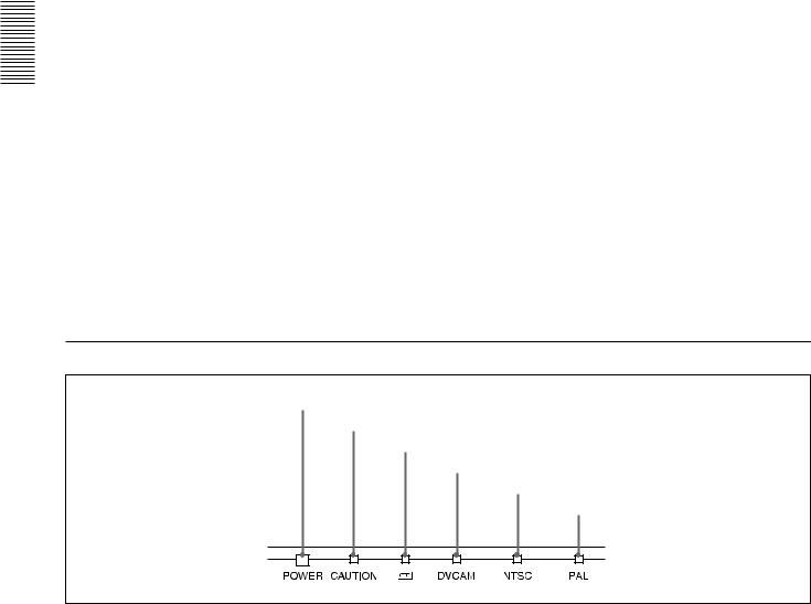
2 Indicators
1 POWER indicator
2 CAUTION indicator
3 q indicator
4 DVCAM indicator
5 NTSC indicator
6 PAL indicator
1 POWER indicator
Lights in green when the power of this unit is on and lights in red when the unit is in the standby mode.
2 CAUTION indicator
Flashes when an error occurs.
For details on cautions, see “Alarm Messages” on page 51 (GB).
3 q (cassette) indicator
Lights when a digital video cassette is loaded. Even if the unit is in the standby mode, the indicator lights as long as the cassette is inside of the unit. While the cassette is being ejected, the indicator flashes.
4 DVCAM indicator
Lights when the unit is playing back a tape recorded in DVCAM format.
When the REC MODE on the VTR SET menu is set to DVCAM, this indicator also lights during recording or in the EE mode.
10 (GB) |
Chapter 1 Overview |
For details on the VTR SET menu, see “VTR SET menu” on page 43 (GB).
5 NTSC indicator
Lights when:
•the unit is in the EE mode, analog video signals are input and the NTSC/PAL select switch is set to NTSC.
•the unit is in the EE mode and NTSC formatted video signals are input from the DV IN/OUT connector.
•a tape that has NTSC formatted video signals is being played back.
6 PAL indicator
Lights when:
•the unit is in the EE mode, analog video signals are input and the NTSC/PAL select switch is set to PAL.
•the unit is in the EE mode and PAL formatted video signals are input from the DV IN/OUT connector.
•a tape that has PAL formatted video signals is being played back.
Rear Panel
9CONTROL S jack
8 RESET button
7NTSC/PAL select switch
1 LANC jack
2DV IN/OUT connector
3 INPUT jacks
4DC IN 12V connector
5AUTO REPEAT switch
6 OUTPUT jacks
Overview 1 Chapter
1 LANC jack
Connects to other video devices that have a LANC jack. You can operate the unit from other video devices.
Notes
•You cannot operate the ejection of a cassette from a device connected to the LANC jack.
•The LANC jack on the unit has only LANC-S functions. The unit has no LANC-M functions.
2 DV IN/OUT connector (4-pin)
Used to input/output a digital signal that complies with the i.LINK standard (Recommended cable: VMC- IL4415(A),VMC-IL4615(A)). Use when an external device which you want to connect to the unit has a DV jack. If you connect the unit and the other device using DV jacks, you can minimize deterioration of picture quality during recording, dubbing or capturing still pictures into a personal computer by digital processing. For details, refer to the instruction manual of the equipment you use.
Note
i.LINK and the i.LINK logo “ ” are trademarks and indicate that this product is in agreement with IEEE 1394-1995 specifications and their revisions.
3 INPUT jacks
Used to input analog video and audio signals. To connect a VCR equipped with S-video output, use the S VIDEO connector on the unit.
4 DC IN 12V connector
Connects to an AC power outlet using the supplied AC power adaptor and power cord.
5 AUTO REPEAT switch
Used to repeat the playback of all or a part of the tape.
For details on the auto repeat function, see “Auto Repeat” on page 32 (GB).
Chapter 1 Overview |
11 (GB) |

Overview 1 Chapter
Location and Function of Parts
6 OUTPUT jacks
Used to output analog video and audio signals. To connect a VCR equipped with S-video input, use the S VIDEO connector on the unit.
Notes
•Various text data are superimposed and output from the VIDEO jack or the S VIDEO connector on the OUTPUT jacks. If you want to output video signals without text data, carry out the following operations.
–Set TITLE DISP and LABEL DISP on the CM SET menu to OFF.
–Depending on the displayed items, press the MENU, DATA CODE, DISPLAY or SEARCH SELECT button on the Remote Commander to
clear the text data on the monitor screen.
For details on text data, see “Displaying data recorded on a tape” on page 25 (GB) and “Displaying various data” on page 26 (GB).
For details on the CM SET menu, see “CM SET menu” on page 46 (GB).
•When the unit is in the EE mode (when the input signal is output as an analog signal), the subcarrier of the color signal is not synchronized with the horizontal sync signal. The color of the picture or the horizontal sync signal may be distorted depending on the type of monitor connected to the unit.
7 NTSC/PAL select switch
Used to switch the color system of signals that will be recorded on the unit when you use analog input.
To change the switch setting, turn off the power of the unit first, then use the tip of a ball-point pen or similar tool to slide this switch.
Before inputting NTSC or PAL formatted analog video signals, set this switch to appropriate position according to the color system of it.
Notes
•If the color system of the input signals is different from that of the switch setting, both picture and sound will be muted.
•When inputting signals to the DV IN/OUT connector or during playback, this switch setting is invalid. The unit detects the color system of the signals automatically.
•When the switch is set to PAL, the unit works as a PAL model. Therefore the time code generated by the unit while recording in the DVCAM format turns to the non-drop frame mode. Even if an NTSC formatted signal is input from the DV IN/OUT connector, the time code generated by the unit is nondrop frame mode as long as the switch is set to PAL, regardless of the TC FORMAT setting on the OTHERS menu. If you intend to set the unit to generate the time code in the drop frame mode, set the switch to NTSC.
•The color system of the signals output from the unit is the one recorded on the tape being played back. The unit cannot convert the color system of signals of one system into that of the other. (For example: converting NTSC formatted signals into PAL formatted signals is not possible) Therefore, to view or record the signal output from the unit, you need a device compatible with the color system of the signals output from the unit.
•When the color system of playback signals is different from the one last used on the unit, playback picture and sound will be distorted and time code will be discontinuous for a short time at the beginning of the playback.
•If you play back a tape with both NTSC and PAL color system recordings, the following limitations apply.
–At the point where the recorded signals format changes, the picture may be distorted or the audio noise may be output.
–The tape transport control buttons may be disabled until the tape running is stabilized.
•Do not change the switch setting during recording.
8 RESET button
Press this button to initialize the internal clock and all menu items. Press this button with the tip of a ballpoint pen or similar tool.
9 CONTROL S jack
Connects to a remote control unit (DSRM-20, not supplied) for controlling this unit.
Note
When using a CONTROL S-device, set the REMOTE CONTROL switch on the front panel to CONTROL S. Otherwise, you cannot operate the unit with CONTROL S-devices.
12 (GB) |
Chapter 1 Overview |
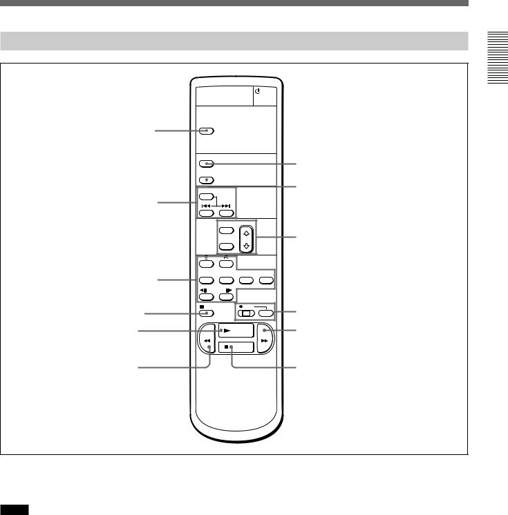
Supplied Remote Commander
 7 On/standby switch
1 TC RESET button |
TC RESET |
|
|
|
|
|
|
|
DISPLAY |
|
8 DISPLAY button |
|
|
|
|
|
DATA CODE |
|
9 DATA CODE button |
|
|
|
|
|
SEARCH SELECT |
|
|
2 SEARCH SELECT |
|
|
|
buttons |
|
|
|
|
MENU |
|
|
|
SET |
|
0 Buttons for menu operation |
|
|
|
|
3 Buttons for |
x1/10 x1/3 |
x1 |
x2 |
playing at various |
|
|
|
speeds |
FRAME |
|
|
4 PAUSE button |
PAUSE |
REC |
qa REC buttons |
|
|
||
5 PLAY button |
|
PLAY |
qs FF button |
|
REW |
|
FF |
|
|
STOP |
|
6 REW button |
|
|
qd STOP button |
Overview 1 Chapter
1 TC RESET button
Press this button to reset the time code to 00:00:00:00 during recording or in the recording pause mode.
Notes
•When the command mode of a Sony device / remote commander is set to VTR 4;
–if you press this button while pointing the Remote Commander toward a Sony device other than this unit, the HMS counter on that machine will be reset to zero.
–if you press a counter reset button on a Sony remote commander while pointing it toward this unit during recording or in the recording pause mode, the time code will be reset to zero.
•This button functions only when the unit or other Sony device is recording in the DVCAM format.
2 SEARCH SELECT buttons
Press these buttons to search for scenes using the search function.
For details on the search function, see “Searching using the search function” on page 29 (GB).
3 Buttons for playing at various speeds
You can play back a tape at normal speed or at a speed other than normal with these buttons.
For details, see “Playing at various speeds” on page 28 (GB).
4 PAUSE button
5 PLAY button
Chapter 1 Overview |
13 (GB) |
Overview 1 Chapter
Location and Function of Parts
6 REW button
7 On/standby switch
8 DISPLAY button
Press this button to see indications, such as time code and tape remaining time, on the monitor screen.
For details on displayed data, see “Displaying various data” on page 26 (GB).
9 DATA CODE button
Press this button to see the data codes (recording date/ time, camera data) on the monitor screen.
For details on data codes, see “Displaying data recorded on a tape” on page 25 (GB).
0 Buttons for menu operation
Press these buttons to operate the menu.
qa REC buttons
When you press these buttons at the same time, the REC and PLAY indicators light and recording begins.
qs FF button
qd STOP button
Note
When using the Remote Commander, set the REMOTE CONTROL switch on the front panel to WIRELESS. Otherwise, you cannot operate this unit with the Remote Commander.
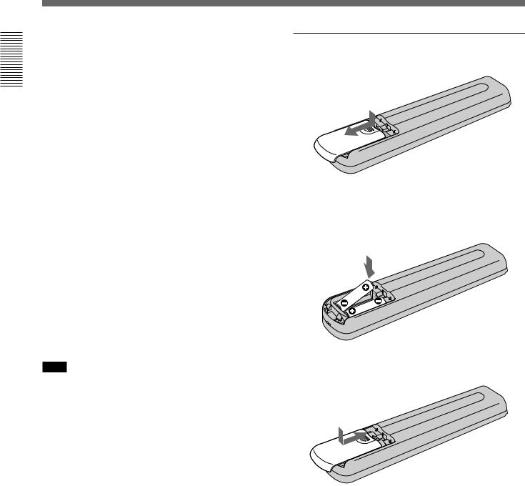
Battery installation
1 Push and slide the lid to open.
2 Install the two size AA (R6) batteries (supplied) with the correct polarity.
Be sure to install the battery from the # side.
3 Replace the lid.
Notes on batteries
•Make sure that the battery orientation is correct when inserting batteries.
•Do not mix an old battery with a new one, or mix different types of batteries.
•If you will not use the Remote Commander for a long time, remove the batteries to avoid damage from battery leakage. If batteries have leaked, remove them, wipe the battery compartment dry and replace the batteries with new ones.
14 (GB) |
Chapter 1 Overview |

Chapter2
Playback and
Recording
Notes on Video Cassettes
Usable cassettes
Use Standard-DVCAM cassettes or Mini-DVCAM cassettes with this unit. The PDV-184 can record programs for 184 minutes (DVCAM format) / 270 minutes (DV format) and the PDVM-40 can record for 40 minutes (DVCAM format) / 60 minutes (DV format).
You can get the highest quality pictures with this digital videocassette recorder using DVCAM cassettes. You may not be able to get as good quality with other cassettes. We recommend using DVCAM cassettes so that you can record your one-time events in the highest quality.
Recording and Playback 2 Chapter
DVCAM cassette
Mini DVCAM cassette
Chapter 2 Playback and Recording |
15 (GB) |
Notes on Video Cassettes
Recording and Playback 2 Chapter
Cassette memory
Cassette memory is an optional feature that is mounted on some Standard DVCAM/DV cassettes and Mini DVCAM/Mini DV cassettes. When you record a program, the recording date and time, and the programs’ position on the tape are stored in the cassette memory so that you can quickly locate the program later on. 


 indicates that you can use the cassettes to store up to 16 kbits of data. On this unit, you can use cassettes on which up to 16 kbits of data can be stored.
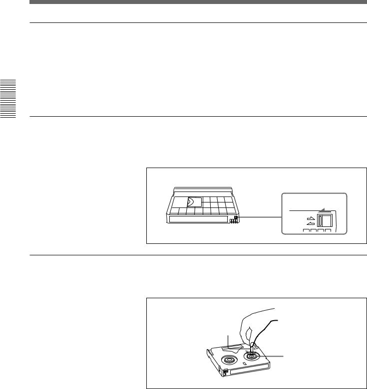
To save a recording
To prevent accidental erasure of a recording, slide the REC/SAVE switch on the cassette so that the red portion becomes visible. To record on a tape, slide the switch so that the red portion is hidden.
REC/SAVE switch |
Set to SAVE. |
REC |
SAVE |
Checking the tape for slack
Using a paper clip or a similar object, turn the reel gently in the direction shown by the arrow. If the reel does not move, there is no slack.
Paper clip, etc.
Reel
16 (GB) |
Chapter 2 Playback and Recording |
Preparations
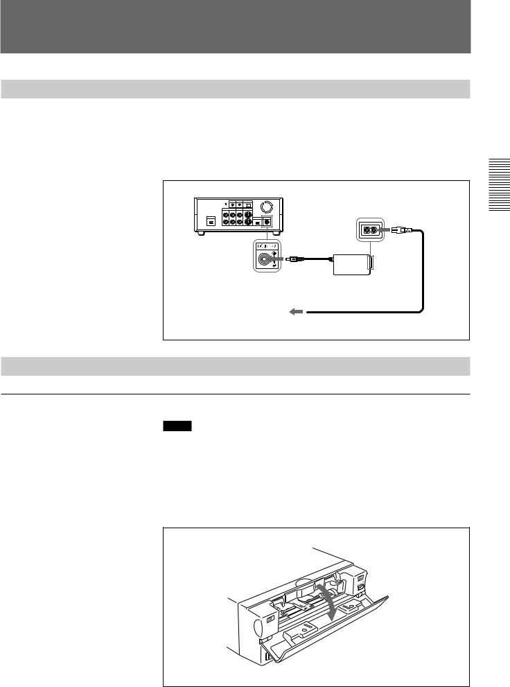
Power Preparations
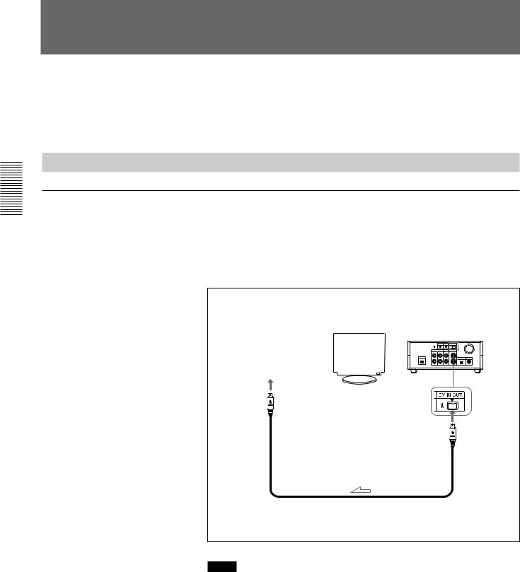
Connect the power cord (supplied) to the AC adaptor (AC-SU1, supplied) and connect the AC adaptor to the DC IN 12V connector on the unit. Then, connect the power plug to the wall outlet.
When you undo these connections, be sure to disconnect the power cord from the wall outlet first.
DSR-11
to DC IN 12V connector
AC adaptor
AC-SU1 (supplied)
Power cord (supplied)
to wall outlet
Inserting/Ejecting Cassettes
To insert a cassette
Notes
•Do not insert the cassette forcibly. The unit may be damaged.
•Do not eject/load the cassette in a place subject to light. Make sure to close the cassette lid when using the unit. The internal sensor of the unit may operate incorrectly if too much light finds its way into the unit.
1 With the unit powered on, confirm that the q indicator is off, then open the cassette lid.
Recording and Playback 2 Chapter
(Continued)
Chapter 2 Playback and Recording |
17 (GB) |

Preparations
2 After checking the tape for slack, hold the cassette so that the tape window is facing upward, then insert it into the unit.
Recording and Playback 2 Chapter
Mini cassette
Insert the mini cassette into the center of the cassette compartment.
Standard cassette
Tape window facing upward
The cassette is automatically loaded into the unit.
3 Close the cassette lid.
To eject the cassette
1 With the unit powered on, open the cassette lid. Press the EJECT button located at the right side of the cassette compartment.
The cassette is unloaded and ejected.
2 Remove the cassette from the unit. Close the cassette lid.
18 (GB) |
Chapter 2 Playback and Recording |

Notes on Recording/Playback
No compensation for contents of the recording
Contents of the recording cannot be compensated for if recording or playback is not successful due to a malfunction of the unit, video tape, etc.
Copyright precautions
On recording
You cannot record any software having copyright protection signals on this unit. If you start recording protected video and audio signals, a warning appears on the monitor screen and the unit stops recording.
On playback
If you play back a software having copyright protection signals on this unit, you may not be able to copy it onto other equipment.
Limitations caused by the difference in format
The unit can record and play back tapes recorded in DVCAM format. It can also record and play back tapes recorded in DV format (SP mode). However, due to the difference in format, you may not be able to record or edit some tapes affected by recording conditions of the tape.
For details, see “Compatibility of DVCAM and DV Format” on page 55 (GB).
Recording and Playback 2 Chapter
Chapter 2 Playback and Recording |
19 (GB) |
Recording and Playback 2 Chapter
PlaybackPlayback
This section describes the necessary connections, settings, and operations to perform playback on this unit. The same settings and operations apply whether you are using the unit for dubbing or as a stand-alone videocassette player.
Connections for Playback
To equipment with a DV jack
Connecting to a computer
The video and audio signals are sent to a computer with virtually no deterioration in quality, enabling high-quality uploading. The signal flow is automatically detected so you do not need to make separate connections for input and output.
Recorder |
|
|
|
|
|
|
|
|
Player |
|
|
Monitor |
|||||||
Computer |
|
|
|
|
|
|
|
|
DSR-11 |
|
|
|
|
|
|
|
|
|
|
|
|
|
|
|
|
|
|
|
|
|
|
|
|
|
|
|
|
|
|
|
|
|
|
|
|
|
|
|
|
|
|
|
|
|
|
|
|
|
|
|
|
|
|
|
|
|
|
|
|
|
|
|
|
|
|
|
|
|
|
to the DV jack
i.LINK cable (DV cable) (not supplied)
l: Signal flow
Notes
•Set DV EE OUT on the VTR SET menu to OFF.
For details on the VTR SET menu, see “VTR SET menu” on page 43 (GB).
•With the DV connection, data codes (recording date/time, camera data) recorded on the source tape are transmitted from this unit (player).
20 (GB) |
Chapter 2 Playback and Recording |
Connecting to another VCR
The video and audio signals are sent to another VCR with virtually no deterioration in quality, enabling high-quality recording. The signal flow is automatically detected so you do not need to make separate connections for input and output.
Recorder |
|
Player |
|
Other VCR |
Monitor |
DSR-11 |
|
|
|||
|
|
||
to the |
to the |
2Chapter |
|
RecordingandPlayback |
|||
DV jack |
LANC jack |
||
|
|||
|
LANC cable (not supplied) |
|
|
|
i.LINK cable (DV cable) (not supplied) |
|
|
|
|
l: Signal flow |
Notes
•Set DV EE OUT on the VTR SET menu to OFF.
For details on the VTR SET menu, see “VTR SET menu” on page 43 (GB).
•With the DV connection, the sound is recorded in the same audio recording mode as that of the source tape. To record in a different audio recording mode from the source tape, use the analog connection instead.
•With the DV connection, data codes (recording date/time, camera data) recorded on the source tape are transmitted from this unit (player). As a result, when you play back a recorded tape on this unit and press the DATA CODE button on the Remote Commander, the same data codes recorded on the source tape are displayed on the monitor screen.
•As for the LANC connection, see “Notes for a LANC connection” on the next page.
Chapter 2 Playback and Recording |
21 (GB) |
Playback
Recording and Playback 2 Chapter
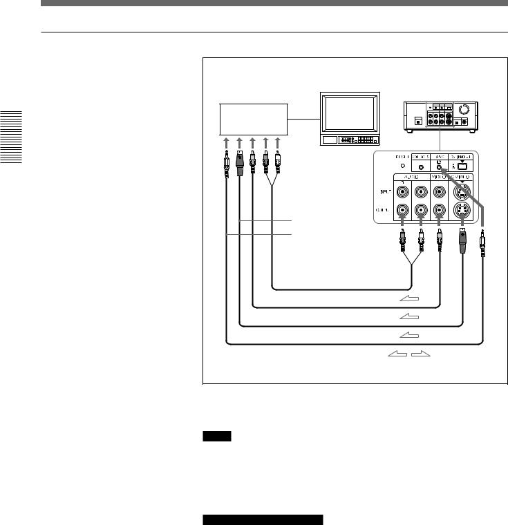
To video equipment without a DV jack
Recorder
Monitor
Other VCR
to the audio input jacks
 to the video input jack
to the S-video input connector to the LANC jack
Audio cable (not supplied)
Video cable (not supplied)
S-video cable (not supplied)
LANC cable (not supplied)
Player
DSR-11
l: Signal flow
Connect either an S-video cable or a video cable as the cable for video signals.
Notes
•When you connect the output jacks of the recorder to the input jacks of this unit, select the input correctly with an input select switch on the recorder to prevent a humming noise or distortion of the picture.
•Distorted signals (e.g., when played back at a speed other than normal) will not be recorded properly.
Notes for a LANC connection
•The LANC connection transmits signals such as control signals, time code, time counter data, and status data.
•Jacks labeled CONTROL L have the same function as LANC jacks. Jacks labeled REMOTE may also have the same function.
•Set the LANC switch on the recorder to M. A device which does not have M / S switch cannot be used to control this unit.
22 (GB) |
Chapter 2 Playback and Recording |

Settings for Playback
Preparation on the player (this unit)
Note
Various text data are superimposed and output from the VIDEO jack or the S VIDEO connector on the OUTPUT jacks. If you want to record video signals without text data, carry out the following operations.
•Set TITLE DISP and LABEL DISP on the CM SET menu to OFF.
•Depending on the displayed items, press the MENU, DATA CODE, DISPLAY or SEARCH SELECT button on the Remote Commander to clear the text data on the monitor screen.
For details on text data, see “Displaying data recorded on a tape” on page 25 (GB) and “Displaying various data” on page 26 (GB).
For details on the CM SET menu, see “CM SET menu” on page 46 (GB).
1 Power on the video monitor, then set the monitor’s input switch according to the signals input from the recorder.
2 Set up the recorder.
For details, refer to the instruction manual of the recorder.
3 Power on this unit by pressing the ON/STANDBY switch on this unit.
4 When you play back a tape recorded in 4-channel mode (Fs32k), adjust the balance between channel 1/2 and channel 3/4 with AUDIO MIX on the AUDIO SET menu.
For details on the AUDIO SET menu, see “AUDIO SET menu” on page 44 (GB).
Note
The AUDIO MIX on the AUDIO SET menu (audio balance adjustment) does not function on the source audio output through the DV IN/OUT connector.
Recording and Playback 2 Chapter
Chapter 2 Playback and Recording |
23 (GB) |

Playback
Playback Procedure
Recording and Playback 2 Chapter
This section describes the procedures used to play back a tape and send signals to another VCR. For details on the procedures required when using a computer as a recorder, refer to the instruction manual of your computer or the user’s manuals of the software installed in it.
1 After checking the tape for slack and confirming that the q indicator is off, hold the cassette so that the tape window is facing upward, then insert it into this unit.
For details on checking the tape for slack, see “Notes on Video Cassettes” on page 15 (GB).
Note
Do not insert the cassette forcibly. The unit may be damaged.
The cassette is automatically loaded into the unit.
2 Press the PLAY button.
This unit starts playback.
To stop playback
Press the STOP button on the unit.
To pause playback
Press the PAUSE button on the unit.
Notes
•When this unit is playing back a part of the tape where the recording format has been changed between the DVCAM format and the DV format, the picture and sound may be distorted.
•This unit cannot play back a tape recorded in the LP mode of the consumer DV format.
24 (GB) |
Chapter 2 Playback and Recording |
Playback Functions
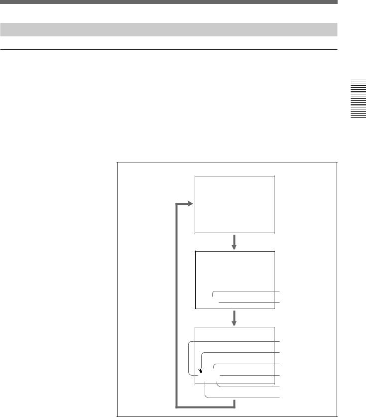
Displaying data recorded on a tape
If you record on a tape using a Sony digital camcorder (DSR-200/200P, 200A/200AP, PD100/PD100P, PD100A/PD100AP, PD150/PD150P, 250/ 250P, etc.), data codes (the shutter speed, SteadyShot, program AE mode, white balance, iris, gain, date and time) can be recorded on the tape. You can check these data items during playback on this unit.
Press the DATA CODE button on the Remote Commander during playback.
Each time you press the DATA CODE button, the display changes as follows.
No indicator
Recording |
|
|
date/time |
|
|
|
|
Date |
2000 12 25 |
Time |
|
19 : 20 : 30 |
||
Camera data |
|
|
|
|
Shutter speed |
|
|
SteadyShot |
|
|
Program AE |
MANUAL |
White balance |
|
10000 ATW |
||
F 1.6 |
0 dB |
|
|
|
Gain |
|
|
Iris |
Recording and Playback 2 Chapter
(Continued)
Chapter 2 Playback and Recording |
25 (GB) |
Recording and Playback 2 Chapter
Playback
Notes
•The data codes are also displayed by setting DATA CODE on the DISPLAY SET menu. You can change the displayed item in the same way as described above.
Example
Menu setting : CAMERA
Display : camera data t no indicator t recording date/time t camera data
For details on the DISPLAY SET menu, see “DISPLAY SET menu” on page 45 (GB).
•Camera data items show the settings of a tape recorded by a digital camcorder (DSR-200/200P, 200A/200AP, PD100/PD100P, PD100A/ PD100AP, PD150/PD150P, 250/250P, etc.). This unit cannot record camera data.
•When the data codes were not recorded, “- - -” appears instead.
•Some of the camera data items displayed on the monitor screen by this unit are different from those shown by the digital camcorder.
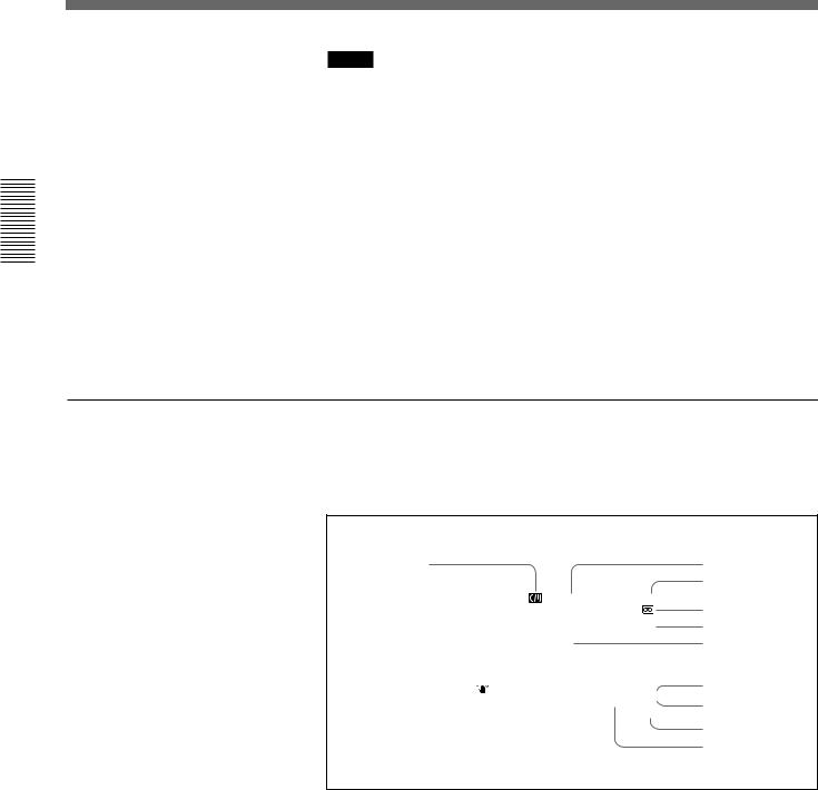
Displaying various data
You can check various data items such as the time code, tape remaining time, etc. on the monitor screen. These data items are useful for normal recording/playback operation.
1 |
|
|
|
|
2 |
|
|
|
|
|
3 |
|
|
|
|
||
|
|
N 00:12:34:12 |
|
||
|
|
|
122min |
|
4 |
|
|
|
PHOTO –10 |
5, 6 |
|
|
|
|
SEARCH |
||
|
|
% |
7 |
||
|
|
|
|
||
|
MANUAL |
DVCAM |
8 |
||
|
|
||||
|
1 0 0 0 0 |
ATW |
NS 48K |
9 |
|
|
F1. 6 |
12 dB |
DV |
I N |
|
|
|
||||
|
|
|
|
|
|
0 qa
An item with * is displayed when you press the DISPLAY button on the Remote Commander.
You can hide the item by pressing the DISPLAY button again.
1 Cassette memory indicator*
This is shown when a cassette with cassette memory has been loaded.
2 Tape transport mode indicator*
Displays the tape transport mode.
26 (GB) |
Chapter 2 Playback and Recording |

3Time code indicator*
•Displays the time code. In the drop frame mode (only for NTSC), a period is displayed between the minute and second. (Example: 00:12.58:00)
•Displays the diagnostics code numbers if the self-diagnostic function is enabled.
4 Tape remaining time indicator*
If qREMAIN on the DISPLAY SET menu has been set to ON, the remaining tape time is displayed.
Note
If the tape has been rewound to the beginning, this indicator will not show the tape time remaining when the tape is inserted into the unit. The remaining tape time is displayed after the tape runs for a while.
5 Search indicator
Displays the search mode when you search for scenes with the Remote Commander or the DSRM-20 (not supplied).
For details on the search function, see “Searching using the search function” on page 29 (GB).
6 Index indicator*
Displays the INDEX MARK when an index has been marked.
7 Caution indicators*
Displays a caution.
For details on cautions, see “Alarm Messages” on page 51 (GB).
8 DVCAM/DV indicator*
In the EE and recording modes, displays the recording format selected in REC MODE on the VTR SET menu. During playback, displays the recording format recorded on the tape.
9 Audio mode indicator*
In the EE and recording modes, displays the audio mode selected in AUDIO MODE on the AUDIO SET menu. During playback, displays the audio mode recorded on the tape. When inputting signals from the DV IN/ OUT connector, displays the audio mode of signals input from the DV IN/ OUT connector.
0 Input signal indicator*
Displays the INPUT SELECT selector setting.
qa NS (Non Standard) audio mode indicator*
This is shown when you play back a tape in the unlock audio mode or when the unlock mode signal has been input from the DV IN/OUT connector. Always this is shown when the REC MODE on the VTR SET menu has been set to DV SP and the unit is in the EE mode.
For details on the unlock mode, see “Compatibility of DVCAM and DV Format” on page 55 (GB).
Recording and Playback 2 Chapter
Chapter 2 Playback and Recording |
27 (GB) |

Playback
Playing at various speeds
Recording and Playback 2 Chapter
You can enjoy playback functions using the Remote Commander.
Playback options |
Operation |
|
|
|
|
Play at 1/10 of normal speed |
Press × |
1/10 during playback. |
|
|
|
Play at 1/3 of normal speed |
Press × |
1/3 during playback. |
|
|
|
Play at normal speed |
Press × |
1 during playback. |
|
|
|
Play at twice the normal speed |
Press × |
2 during playback. |
|
|
|
Play frame by frame |
Press FRAME c/C during pause. |
|
|
If you keep pressing one of these buttons, |
|
|
playback continues, frame by frame. |
|
|
|
|
To change playback direction
Press the FRAME c/Cbuttons during playback at various speeds. To play back in the forward direction, press the C button; in the backward direction, press the cbutton.
To hear the sound when playing at various speeds
If you want to hear the sound when playing at various speeds, set JOG AUDIO on the AUDIO SET menu to ON.
For details on the AUDIO SET menu, see “AUDIO SET menu” on page 44 (GB).
Note
When the command mode of a Sony device / remote commander is set to VTR 4;
•if you press the × 1/3 button while pointing the Remote Commander toward a Sony device other than this unit, the playback speed may turn to 1/5 of normal speed.
•if you press the × 1/5 button on a remote commander while pointing it toward this unit, the playback speed will turn to 1/3 of normal speed.
28 (GB) |
Chapter 2 Playback and Recording |
Searching using the search function
There are four kinds of search available on this unit:
–Searching for the beginnings of recordings: Index search
–Searching for the boundaries of recorded tape by title: Title search*
–Searching for a point on the tape where the recorded date changes: Date search
–Searching for scenes recorded in the photo mode with a digital
camcorder: Photo search
*:A function available only on a cassette with cassette memory
Searching with the cassette memory
If you set the CM SEARCH on the CM SET menu to ON and the tape has cassette memory, the recordings are listed in the chronological order in which they were made. You can search using this chronological list.
If the tape does not have cassette memory, you cannot search for scenes in chronological order.
For details on the CM SET menu, see “CM SET menu” on page 46 (GB).
1 Press the SEARCH SELECT button on the Remote Commander to select the search type: INDEX, TITLE, DATE or PHOTO SEARCH.
A chronological list appears on the monitor screen.
When selecting INDEX SEARCH
I NDEX SEARCH |
|
CH |
||||||
|
|
|
|
|
|
|
|
|
1 |
0 0 |
/ |
2 |
/ |
2 8 |
1 |
: 0 0 |
LINE |
2 |
0 0 |
/ |
3 |
/ |
7 |
1 2 |
: 5 9 |
LINE |
3 |
0 0 |
/ |
3 |
/ |
1 1 |
3 |
: 0 5 |
LINE |
4 |
0 0 |
/ |
5 |
/ |
5 |
1 9 |
: 0 0 |
LINE |
5 |
0 0 |
/ |
7 |
/ |
3 |
1 0 |
: 1 5 |
LINE |
6 |
0 0 |
/ 1 0 / |
2 8 |
1 2 |
: 2 0 |
LINE |
||
v |
|
|
|
|
|
|
|
|
q
The date and time display can be changed by setting DATE DISP and TIME DISP on the DISPLAY SET menu.
For PAL model, “PROG” is displayed instead of “CH.”
For details on the DISPLAY SET menu, see “DISPLAY SET menu” on page 45 (GB).
2 Press the .or >button to select a recording.
The unit starts searching and when it locates the recording, begins playback. During Photo search, the unit turns to the playback pause mode.
Recording and Playback 2 Chapter
Chapter 2 Playback and Recording |
29 (GB) |
Playback
Recording and Playback 2 Chapter
Searching without cassette memory
When you use a tape without cassette memory, the unit searches in the order of the actual positions of the recordings, regardless of the setting of CM SEARCH on the CM SET menu.
When you use a tape with cassette memory, set CM SEARCH on the CM SET menu to OFF.
For details on the CM SET menu, see “CM SET menu” on page 46 (GB).
Note
The title search is not available in searching without cassette memory.
1 Press the SEARCH SELECT button on the Remote Commander to select the search type.
When selecting INDEX SEARCH
INDEX 00
SEARCH
2 Press the .or >button repeatedly to locate the recording you want.
Each time you press the .or >button, the unit searches for the previous or next search point. When an search point is located, its number is indicated on the monitor screen.
The unit starts searching backwards or forwards until the number comes to zero, then plays back the recording. During Photo search, the unit turns to the playback pause mode.
How signals are recorded
There are four different signal types, one for each search method; index, title, date and photo signals. They are recorded by the digital camcorder (DSR-200/200P, 200A/200AP, PD100/PD100P, PD100A/PD100AP, PD150/PD150P, 250/250P, etc.). However, the type of signal recorded and where it is recorded (on the tape or in the cassette memory) depends on whether the cassette has cassette memory or which type of video equipment is used for recording. Please note that if the signals for a certain search type are not recorded, you cannot do that type of search. For details on the signals used for a particular type of search, refer to the instruction manual of the recorder.
30 (GB) |
Chapter 2 Playback and Recording |
 Loading...