


3-869-570-12(1)
Digital
Videocassette
Recorder
Operating Instructions
Before operating the unit, please read this manual thoroughly and retain it for future reference.
DSR-2000A/2000AP
2005 Sony Corporation
Owner’s Record
The model and serial numbers are located in the rear. Record these numbers in the spaces provided below. Refer to them whenever you call upon your Sony dealer regarding this product.
Model No. |
|
Serial No. |
Important Safety Instructions
•Read these instructions.
•Keep these instructions.
•Heed all warnings.
•Follow all instructions.
•Do not use this apparatus near water.
•Clean only with dry cloth.
•Do not block any ventilation openings.
Install in accordance with the manufacturer’s instructions.
•Do not install near any heat sources such as radiators, heat registers, stoves, or other apparatus (including amplifiers) that produce heat.
•Do not defeat the safety purpose of the polarized or grounding-type plug. A polarized plug has two blades with one wider than the other. A grounding-type plug has two blades and a third grounding prong. The wide blade or the third prong are provided for your safety. If the provided plug does not fit into your outlet, consult an electrician for replacement of the obsolete outlet.
•Protect the power cord from being walked on or pinched particularly at plugs, convenience receptacles, and the point where they exit from the apparatus.
•Only use attachments/accessories specified by the manufacturer.
•Use only with the cart, stand, tripod, bracket, or table specified by the manufacturer, or sold with the apparatus.
When a cart is used, use caution when moving the cart/apparatus combination to avoid injury from tip-over.
•Unplug this apparatus during lightning storms or when unused for long periods of time.
•Refer all servicing to qualified service personnel. Servicing is required when the apparatus has been damaged in any way, such as power-supply cord or plug is damaged, liquid has been spilled or objects have fallen into the apparatus, the apparatus has been exposed to rain or moisture, does not operate normally, or has been dropped.
WARNING
To prevent fire or shock hazard, do not expose the unit to rain or moisture.
To avoid electrical shock, do not open the cabinet. Refer servicing to qualified personnel only.
THIS APPARATUS MUST BE EARTHED.
CAUTION
The apparatus shall not be exposed to dripping or splashing and no objects filled with liquid, such as vases, shall be placed on the apparatus.
Television programs, films, video tapes and other materials may be copyrighted.
Unauthorized recording of such material may be contrary to the provisions of the copyright laws.
This symbol is intended to alert the user to the presence of uninsulated “dangerous voltage” within the product’s enclosure that may be of sufficient magnitude to constitute a risk of electric shock to persons.
This symbol is intended to alert the user to the presence of important operating and maintenance (servicing) instructions in the literature accompanying the appliance.
WARNING: THIS WARNING IS APPLICABLE FOR USA ONLY.
Using this unit at a voltage other than 120 V may require the use of a different line cord or attachment plug, or both. To reduce the risk of fire or electric shock, refer servicing to qualified service personnel.
2

For customers in the USA (DSR-2000A only)
This equipment has been tested and found to comply with the limits for a Class A digital device, pursuant to Part 15 of the FCC Rules. These limits are designed to provide reasonable protection against harmful interference when the equipment is operated in a commercial environment. This equipment generates, uses, and can radiate radio frequency energy and, if not installed and used in accordance with the instruction manual, may cause harmful interference to radio communications. Operation of this equipment in a residential area is likely to cause harmful interference in which case the user will be required to correct the interference at his own expense.
You are cautioned that any changes or modifications not expressly approved in this manual could void your authority to operate this equipment.
The shielded interface cable recommended in this manual must be used with this equipment in order to comply with the limits for a digital device pursuant to Subpart B of Part 15 of FCC Rules.
For the customers in Europe (DSR-2000AP only)
This product with the CE marking complies with both the EMC Directive (89/336/EEC) and the Low Voltage Directive (73/23/EEC) issued by the Commission of the European Community.
Compliance with these directives implies conformity to the following European standards:
•EN60065: Product Safety
•EN55103-1: Electromagnetic Interference (Emission)
•EN55103-2: Electromagnetic Susceptibility (Immunity) This product is intended for use in the following Electromagnetic Environment(s):
E1 (residential), E2 (commercial and light industrial), E3 (urban outdoors) and E4 (controlled EMC environment, ex. TV studio).
Voor de Klanten in Nederland
•Dit apparaat bevat een vast ingebouwde batterij die niet vervangen hoeft te worden tijdens de levensduur van het apparaat.
•Raadpleeg uw leverancier indien de batterij toch vervangen moet worden.
De batterij mag alleen vervangen worden door vakbekwaam servicepersoneel.
•Gooi de batterij niet weg maar lever deze in als klein chemisch afval (KCA).
•Lever het apparaat aan het einde van de levensduur in voor recycling, de batterij zal dan op correcte wijze verwerkt worden.
3

TableTableof CofntentsContents
Chapter 1
Overview
Features ............................................................................. |
8 |
DVCAM Format .................................................................... |
8 |
Variety of Interfaces ............................................................... |
9 |
Full Functionality for More Efficient Editing ........................ |
9 |
Other Features ...................................................................... |
11 |
Options ................................................................................. |
11 |
System Configuration .................................................... |
12 |
Location and Function of Parts ..................................... |
13 |
Upper Control Panel ............................................................. |
14 |
Lower Control Panel ............................................................ |
17 |
Subsidiary Control Panel ..................................................... |
26 |
Connector Panel ................................................................... |
29 |
Usable Cassettes ............................................................ |
34 |
Inserting and Ejecting Cassettes .......................................... |
35 |
Chapter 2
Setting/Displaying
Time Data and Text
Information
Displaying Time Data and Unit’s Operating Status- |
|
Superimposing Text Information ................................... |
36 |
Setting Time Code and User Bits .................................. |
40 |
Synchronizing the Internal Time Code Generator With an |
|
External Signal—External Lock .......................................... |
43 |
Chapter 3
Recording and
Playback
Recording ........................................................................ |
45 |
Preparations for Recording .................................................. |
45 |
Recording Time Code and User Bit Values .......................... |
47 |
Recording Operation ............................................................ |
48 |
Playback .......................................................................... |
49 |
Preparations for Playback .................................................... |
49 |
Playback Operation .............................................................. |
50 |
Dynamic Motion Control (DMC) Playback......................... |
55 |
Synchronous Playback ......................................................... |
59 |
Digitally Dubbing Signals in DVCAM Format ............... |
61 |
4 Table of Contents

Chapter 4
Editing
Automatic Editing ........................................................... |
66 |
Overview of Automatic Editing ........................................... |
66 |
Button/Switch Settings for Editing ...................................... |
69 |
Selecting an Edit Mode ........................................................ |
70 |
Setting Edit Points ................................................................ |
71 |
Checking Edit Points ............................................................ |
74 |
Modifying Edit Points .......................................................... |
75 |
Cuing Up to Edit Points ....................................................... |
77 |
Checking Edit Results—Preview ......................................... |
79 |
Executing Automatic Editing ............................................... |
80 |
DMC Editing .................................................................... |
83 |
Overview of DMC Editing ................................................... |
83 |
Carrying Out DMC Editing.................................................. |
84 |
Preread Editing ............................................................... |
86 |
Special Editing Methods ................................................ |
88 |
Quick Editing ....................................................................... |
89 |
Continuous Editing .............................................................. |
90 |
Standalone Editing ............................................................... |
92 |
Manual Editing ..................................................................... |
93 |
Adding a Narration (Sound-on-Sound) ................................ |
94 |
Chapter 5
ClipLink Operation
Overview of ClipLink Operation .................................... |
95 |
Displaying ClipLink Log Data ........................................ |
96 |
Detailed Data Display .......................................................... |
96 |
Cuing Up to Mark IN/OUT and Cue Points .................... |
97 |
Cuing Up to Any Desired Position ....................................... |
97 |
Cuing Up to Adjacent Mark IN/Cue Points ......................... |
97 |
Rewriting ClipLink Log Data .......................................... |
98 |
Changing the Reel Number .................................................. |
98 |
Changing Mark IN/OUT Points ........................................... |
98 |
Changing the OK/NG Status ................................................ |
99 |
|
(Continued) |
Table of Contents |
5 |

Table of Contents
Chapter 5
ClipLink Operation
Adding to/Deleting From ClipLink Log Data .............. |
101 |
|
Adding Mark IN/OUT Points ............................................ |
101 |
(Continued) |
|
|
|
Deleting Mark IN/OUT Points ........................................... |
101 |
|
Automatically Creating New ClipLink Log Data ......... |
103 |
Chapter 6
Setup Menu
Menu System Configuration ........................................ |
105 |
Basic Menu .................................................................... |
105 |
Items in the Basic Menu..................................................... |
105 |
Basic Menu Operations ...................................................... |
108 |
Extended Menu ............................................................. |
111 |
Items in the Extended Menu .............................................. |
111 |
Extended Menu Operations ................................................ |
121 |
Chapter 7
Connections and
Settings
Reference Video Signals for Analog Signal |
|
Editing ........................................................................... |
123 |
Connections for Cut Editing Using i.LINK |
|
Interface ......................................................................... |
124 |
Connections for a Digital Nonlinear Editing |
|
System ........................................................................... |
125 |
Connections for Digital Nonlinear Editing Using |
|
SDTI (QSDI) Interface ................................................... |
126 |
Connections for Cut Editing Using SDI Interface ...... |
127 |
Connections for Preread Editing ................................ |
128 |
Settings Required When Connecting an External |
|
Editing Control Unit ...................................................... |
129 |
Timecode Settings on This Unit ......................................... |
129 |
Settings on Editing Control Units ...................................... |
129 |
Connections for Component Analog Recording ....... |
130 |
Connections for Two-Unit Synchronous Playback .... |
131 |
Connections for Digitally Dubbing Signals in |
|
DVCAM Format ............................................................. |
132 |
6 Table of Contents

Chapter 8
Maintenance and
Troubleshooting
Appendixes
Condensation ................................................................ |
133 |
Head Cleaning............................................................... |
133 |
Periodic Maintenance ................................................... |
134 |
Troubleshooting............................................................ |
135 |
Error Messages................................................................... |
137 |
Alarm Messages ................................................................. |
137 |
Notes on Use ................................................................. |
140 |
Specifications ............................................................... |
141 |
Glossary ........................................................................ |
144 |
Index .............................................................................. |
147 |
Table of Contents |
7 |

Overview 1 Chapter
Chapter1
Overview
Features
The DSR-2000A/2000AP is a 1/4-inch digital videocassette recorder using the DVCAMTM digital recording format. It uses a component video system, with separate luminance and chrominance signals and digital processing to enable stable, high-quality video. This unit is equipped with a variety of functions needed for videocassette recorders and players used in video editing. By combining two units, you can easily assemble a cut editing system. It is also equipped with a wide range of digital and analog interfaces, to support a variety of different editing systems, including conventional analog systems and mixed digital and analog systems.
Furthermore, it is equipped with an i.LINK interface as standard equipment, making it easy to connect to nonlinear DV editing systems.
The following are the principal features of the unit.
DVCAM Format
DVCAM is a professional 1/4-inch digital recording format developed by Sony from the consumer DV component digital format (4:1:1 for DSR-2000A/4:2:0 for DSR-2000AP).
High image quality and high stability
The luminance and chrominance signals are encoded separately, with 1/5 compression to enable stable, highquality video.
Since this is a digital system, nth-generation copies created by repeated dubbing show virtually no loss in picture quality.
Wide track
The recording track width is 15 µm, 50% wider than the 10 µm of the DV format. This ensures adequate reliability for professional use.
PCM digital audio for high sound quality
The PCM encoding method yields a high audio quality, with wide dynamic range and high signal-to- noise ratio.
There are two recording modes: two-channel mode (48-kHz sampling and 16-bit quantization), which offers sound quality equivalent to the DAT (Digital Audio Tape) format, or four-channel (32-kHz sampling and 12-bit quantization).
8 |
Chapter 1 Overview |

Playback compatibility with DV and DVCPRO formats
A DV cassette recorded on a DV format VCR as well as a DVCPRO(25M) format recorded cassette can be played back on this unit.
Note
When playing back a tape recorded in DVCPRO (25M) format, the SDTI and i.LINK outputs (see the section “Digital interfaces”) of this unit is subjected to muting. Furthermore, it is not possible to playback the cue-audio track of the tape.
Support for three cassette sizes
There are two sizes of DVCAM cassette: standard and mini. You can use either size with this unit.
The unit also accepts L and M sizes of DVCPRO cassette.
•The reel mechanism automatically adjusts to the size of cassette inserted.
•The capacity of a standard cassette is 184 minutes of recording/playback, and that of a mini cassette is 40 minutes.
• AES/EBU
This interface allows the unit to input or output digital audio signals in AES/EBU format.
• i.LINK (DV)3)
This interface allows the unit to input and output digital video and audio signals in DV format.
Analog interfaces
A wide range of analog interfaces is provided, allowing this unit to be connected to various video and audio devices.
•Analog video: Composite, component and S-video interfaces are provided.
•Analog audio: There are four input channels and four output channels. There is also support for microphone input.
Connection to external control devices
You can connect an external control device such as an editor with an RS-422A interface and a remote controller for the built-in digital video processor.
Variety of Interfaces
Digital interfaces
The unit can use the following digital interfaces.
• SDTI (QSDI)1)
This interface allows video, audio and time code signals in SDTI (QSDI) format to be transferred at normal speed between this unit and the ES-7 EditStation. When this unit is connected to another DVCAM VCR, it is possible to copy compressed signals between the two VCRs.
• SDI2)
This interface allows the unit to input or output D1 (component) digital video and audio signals.
Full Functionality for More
Efficient Editing
This unit has a number of functions which assist in efficient and precise editing.
With two DSR-2000A/2000AP units together, you can carry out automatic or manual editing, using either assemble or insert editing.
The system also provides a powerful range of functions for setting and amending edit points, preview, review, and other aspects of efficient editing.
.........................................................................................................................................................................................
1)SDTI (QSDI): SDTI (Serial Data Transport Interface) is the name of a standard interface established as SMPTE 305M.
This unit uses SDTI to transmit DV data, and the input/ output connectors are labled “SDTI(QSDI)”.
In indicator and menu indications, however, the “SDTI(QSDI)” name is shortened to “SDTI”.
2)SDI: Serial Digital Interface is used for transferring video signals in component digital format (D1).
3)is a trademark of Sony Corporation and indicates that this product is in agreement with IEEE1394-1995 specifications and their revisions.
Overview 1 Chapter
Chapter 1 Overview |
9 |

Overview 1 Chapter
Features
DMC (dynamic motion control) editing
You can save a varying speed, in the range −1 to +1 times normal speed1), for an editing segment, and automatically edit with this varying speed.
Split editing
In insert editing, this allows the audio IN and OUT points to be set separately from the video IN and OUT points.
Preread editing
The audio or video on the tape can be read out using the preread heads. The signals then can be processed and rerecorded where they have been.
Cross-fade editing
For audio editing, you can select from cut-in editing, fade-in/fade-out editing, and cross-fade editing.
Support for ClipLink function
This unit accepts instructions from an EditStation, to transfer to the EditStation ClipLink log data held in the cassette memory or index pictures recorded on the tape. On the EditStation you can use these images and data to carry out editing operations efficiently.
•Displaying ClipLink log data
•Changing ClipLink log data OK/NG status
•Cuing up to Mark IN and cue points provided by ClipLink log data
•For cut editing, copying Mark IN data from ClipLink log data
Internal time code generator and reader
An internal timecode generator and reader enables timecode compliant with SMPTE/EBU format to be recorded and played back. This allows editing to single frame precision.
Outputting or inputting timecode (LTC) to or from an external device is also possible using the TIME CODE IN/OUT connectors.
The unit is also compatible with VITC.
High-speed search function
You can carry out color picture searches during fast forward and rewind at speeds up to 85 times normal speed.
When controlling the unit in shuttle mode from an editor or remote control unit, you can search at any speed in the range +60 to –60 times normal speed. In jog mode a frame by frame search is possible. During playback in the range +10 to –10 times normal speed, high-speed audio playback is also possible.
Digital slow motion playback
Using the frame memory function, noiseless slow motion playback is possible at any speed in the range +1 to –1 times normal speed.
Digital jog sound function
When searching at speeds in the range +1 to +1/30 or
–1/30 to –1 times normal speed, the digital jog sound function is enabled. The audio signal is saved in temporary memory, and replayed according to the search speed. This allows searching on the sound track.
Video process control
For analog video output and SDI-format video output, you can adjust the video output level, chroma signal output level, setup level (for DSR-2000A), black level (for DSR-2000AP), and chroma phase.
.........................................................................................................................................................................................
1)The positive direction refers to forward movement of the tape, and the negative direction to reverse movement.
10 Chapter 1 Overview
Other Features |
Options |
Menu operations for functions and operating settings
To make it easier to use this unit for any particular purpose, various functions and operating settings are provided in the menu system.
Superimposing function
Timecode, operating mode, error messages, and other text information, can be superimposed on the SDI video signal and analog composite video signal output.
Functions for easy maintenance
•Self-diagnosis and alarm function: This automatically detects incorrect operations or connections, operating faults, and so forth, and displays details of the problem, the cause, and the action to be taken, in the control panel display section.
•Digital hours meter: This keeps four cumulative counts of the powered on time, the drum rotation time, the tape transport time, and the number of tape threadings and unthreadings, and displays them in the control panal display section.
Compatible with wide screen aspect ratio (16:9)
The unit can record and play back aspect ratio information. When video accompanied by wide-screen aspect ratio information is recorded or played back, the unit can output the video signal also containing the aspect ratio information.
Rack mountable
Using an optional rack mount kit, you can mount the unit in an EIA standard 19-inch rack (height: 4 units).
RMM-131/1 Rack Mount Kit
This kit can be used to mount the unit in an EIAstandard 19-inch rack.
Overview 1 Chapter
Chapter 1 Overview 11

Overview 1 Chapter
System Configuration
|
|
|
The figure below shows example equipment that can |
|
|
Note |
|
|
be connected to this unit. |
Production of some of the peripherals and related |
|
|
devices shown below has been discontinued. For |
|
|
advice about choosing devices, please contact your |
|
|
Sony dealer or a Sony sales representative. |
|
DVCAM cassette |
SDI INPUT/OUTPUT |
|
|
DVCAM camcorder |
|
|
DVW/MSW series VCR etc. |
DV cassette |
|
DV camcorder |
|
|
i.LINK |
i.LINK |
|
DV camcorder |
Nonlinear editing system |
|
|
|
SDTI(QSDI) |
|
INPUT/OUTPUT |
DVCAM camcorder |
COMPONENT |
i.LINK |
|
|
VIDEO IN/OUT |
ANALOG VIDEO I/O |
|
S VIDEO IN/OUT |
|
|
ES-7/ES-3 EditStation |
DSR-2000A/2000AP (this unit)
Analog VCR
Analog Betacam VCR
Microphone Headphones
Video monitor
Audio monitor system
12 Chapter 1 Overview
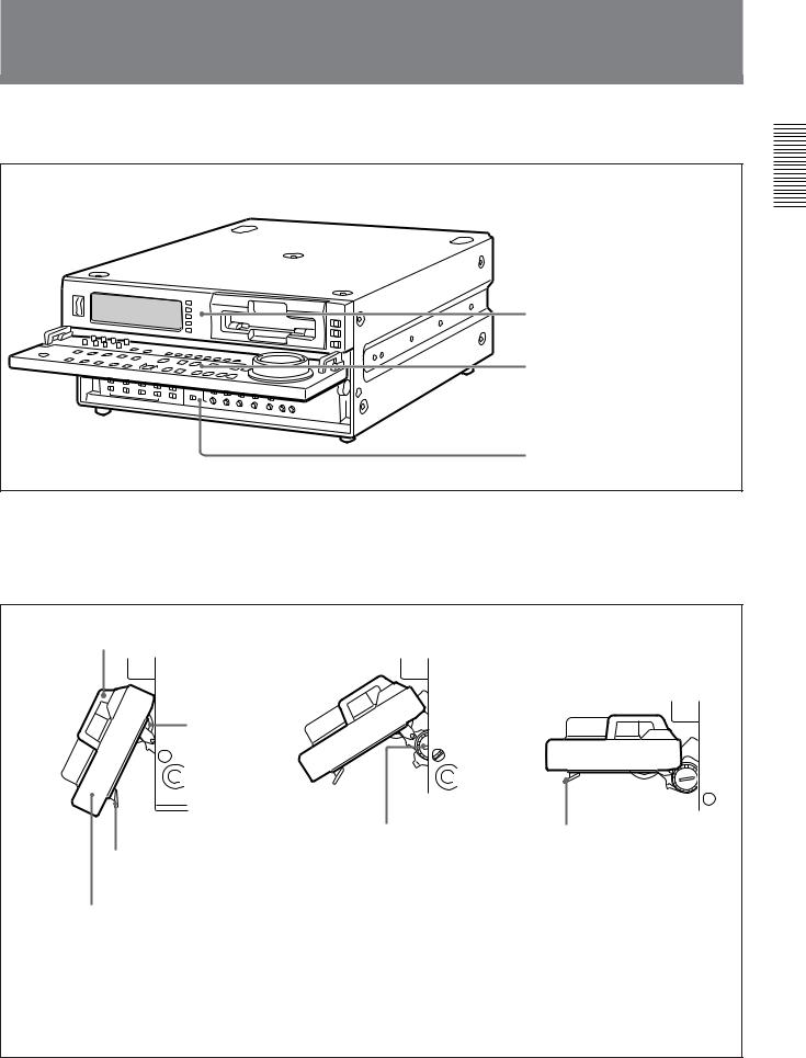
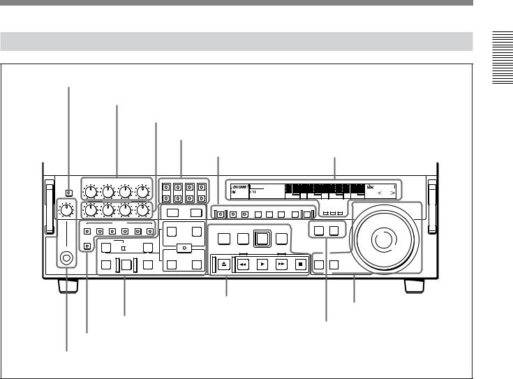
Location and Function of Parts
There are four control panels as shown in the figure below.
 Connector panel (See page 29.)
Upper control panel (See page 14.)
Lower control panel (See page 17.)
Subsidiary control panel (See page 26.)
To adjust the position of the lower control panel
You can fix the lower control panel in any position between vertical and horizontal for ease of operation.
Handle
Lock knob
When the panel is at the desired angle, turn both lock knobs to fix in position.
Release lever
If you raise the panel to the horizontal, it automatically locks in position.
To lower the panel, press both release levers.
Raise the panel by holding both ends or both handles.
To fix the panel at an angle where the lock knobs are inaccessible
1First position the panel at the desired angle, then without tightening the lock knobs, press the release levers and raise the panel to the horizontal.
2With the panel horizontal, tighten the lock knobs, then press the release levers and return the panel to the desired position, where it will lock into place.
Overview 1 Chapter
Chapter 1 Overview 13

Overview 1 Chapter
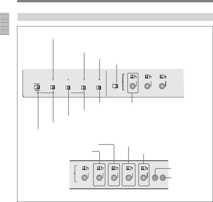
Location and Function of Parts
Upper Control Panel
1 POWER switch
2Audio level meters
1 Input selection/audio mode display section
(see below)
2 Input selection section
(see page 15)
|
|
|
|
|
|
|
|
|
|
|
|
|
|
|
|
|
|
|
|
|
|
|
INPUT SELECT |
|
POWER |
|
|
|
|
|
|
|
|
|
|
|
|
|
|
|
|
SDTI/i.LINK |
|||||||
dB OVER dB |
dB OVER dB |
dB OVER dB |
dB OVER dB |
INPUT |
V:SDTI |
|
SDTI |
i.LINK |
|
|
|
|
||||||||||||
|
|
|
0 |
|
2 |
0 |
|
2 |
0 |
|
2 |
0 |
|
2 |
|
|
|
|
|
VIDEO IN |
||||
|
|
|
|
|
|
|
|
|
|
|
VIDEO |
COMPOSITE |
Y-R,B S VIDEO SDI |
SG |
|
|
|
|||||||
|
|
|
|
|
|
|
|
|
|
|
|
|
|
|||||||||||
|
|
|
-12 |
|
|
-12 |
|
1 |
-12 |
|
1 |
-12 |
|
1 |
|
|
|
|||||||
|
|
|
|
|
|
|
|
|
|
|
||||||||||||||
|
|
|
|
1 |
|
|
|
|
|
|
||||||||||||||
|
|
|
|
|
|
|
|
|
|
|||||||||||||||
|
|
|
-20 |
|
|
-20 |
|
0 |
-20 |
|
0 |
-20 |
|
0 |
CH11/2 |
ANALOG |
AES/EBU |
SDI |
SG |
|
|
|
CH-1,1/2 |
|
|
|
|
|
|
|
|
|
|
|
|||||||||||||||
|
|
|
|
0 |
|
|
|
|
|
|
||||||||||||||
|
|
|
|
|
|
|
|
|
||||||||||||||||
|
|
|
|
|
|
|
|
-1 |
|
|
-1 |
|
|
-1 |
AUDIO |
|
|
|||||||
|
|
|
-30 |
|
-1 |
-30 |
|
-30 |
|
-30 |
|
ANALOG |
AES/EBU |
SDI |
SG |
|
|
|
|
|||||
|
|
|
|
|
|
|
|
|
|
|
||||||||||||||
|
|
|
|
|
|
|
|
|
|
|
||||||||||||||
|
|
|
|
|
|
|
|
|
|
|
CH23/4 |
|
|
|
|
|||||||||
|
|
|
-40 |
|
-2 |
-40 |
|
-2 |
-40 |
|
-2 |
-40 |
|
-2 |
|
|
|
|
|
|
|
|
CH-2,3/4 |
|
|
|
|
|
|
|
|
|
|
|
|
|
|
|
|
||||||||||
|
|
|
|
|
|
|
|
|
|
|
PB FS |
48k44.1k32k |
REC MODE |
2CH4CH |
|
|
|
|||||||
|
|
|
-60 |
|
1 |
-60 |
|
2 |
-60 |
|
3 |
-60 |
|
4 |
|
|
|
|
||||||
|
|
|
|
|
|
|
|
|
|
|||||||||||||||
|
|
|
|
|
|
|
|
|
|
|
|
|
|
|
|
|
|
|
|
|
|
|
|
|
MIXING
3 Cassette compartment
3 Remote control setting section
(see page 16)
REMOTE
9PIN
i.LINK
1 POWER switch
Press the “1” side to power the unit on. When the unit is powered on, the display windows in the upper and lower control panels light.
To power the unit off, press the “¬”side of the switch.
2 Audio level meters
These show the audio levels of channels 1 to 4 (recording levels in recording mode or E-E mode1) and playback level in playback mode).
There are two modes for audio level indications: FULL and FINE, selected by the METER FULL/FINE button on the lower control panel.
3 Cassette compartment
Accepts DVCAM, DV and DVCPRO(25) videocassettes.
For details of usable cassettes, see page 34.
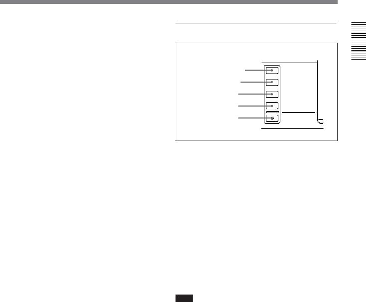
1 Input selection/audio mode display section
|
|
|
|
|
|
|
|
1 INPUT display |
INPUT |
V:SDTI |
|
SDTI |
i.LINK |
|
|
2 INPUT VIDEO display |
VIDEO |
COMPOSITE |
Y-R,B S VIDEO SDI |
SG |
|
||
3 AUDIO CH1, 1/2 display |
CH11/2 |
ANALOG |
AES/EBU |
SDI |
SG |
|
|
4 AUDIO CH2, 3/4 display |
AUDIO |
ANALOG |
AES/EBU |
SDI |
SG |
|
|
CH23/4 |
|
||||||
|
|
|
|
|
|
|
|
5 PB FS display |
PB FS |
48k44.1k32k |
REC MODE |
2CH4CH |
6 REC MODE display |
||
|
|
|
|
|
|
|
|
|
|
|
|
|
|
|
|
.........................................................................................................................................................................................
1)E-E mode: Abbreviation of “Electric-to-Electric mode”. In this mode, video and audio signals input to the VCR are output after passing through internal electric circuits,
but not through magnetic conversion circuits such as heads and tapes. This can be used to check input signals and for adjusting input signal levels.
14 Chapter 1 Overview
1 INPUT display
Indicates the input signal selected with the SDTI/ i.LINK button in the input selection section.
V:SDTI: Digital video signal in SDTI(QSDI) format In this mode, you can select any audio input, though the video signal is recorded with a delay of two frames with respect to the audio input.
SDTI: Digital video and audio signals in SDTI(QSDI) format
i.LINK: Digital video and audio signals in DV format, using i.LINK technology
2 INPUT VIDEO display
Indicates the input video signal selected with the VIDEO IN button in the input selection section.
COMPOSITE: Composite video signal
Y-R, B: Y, R−Y and B−Y component video signals S VIDEO: S-video signal
SDI: SDI video signal SG: Video test signal
3 AUDIO CH1, 1/2 display
Indicates the input audio signal selected with the CH1, 1/2 button in the input selection section.
ANALOG: Analog audio signal
AES/EBU: Digital audio signal in AES/EBU format SDI: SDI audio signal
SG: Audio test signal
4 AUDIO CH2, 3/4 display
Indicates the input audio signal selected with the CH2, 3/4 button in the input selection section. The indications available are the same as for the AUDIO CH1, 1/2 display described above.
5 PB FS (playback audio sampling frequency) display
Indicates the sampling frequency (48 kHz, 44.1 kHz or 32 kHz) at which audio is recorded on tape.
6 REC MODE (audio recording mode) display
Indicates the audio recording mode (2CH or 4CH) selected with extended menu item 818.
2 Input selection section
1 SDTI/i.LINK button |
INPUT SELECT |
SDTI/i.LINK |
|
2 VIDEO IN button |
VIDEO IN |
3 CH1, 1/2 button |
CH-1,1/2 |
4 CH2, 3/4 button |
CH-2,3/4 |
5 MIXING button |
MIXING |
1 SDTI/i.LINK (SDTI(QSDI) interface/i.LINK selection) button
Each press of this button cycles through the following input signal selection options.
•Digital video signal in SDTI(QSDI) format input to the SDTI(QSDI) INPUT connector
When this is selected, use the CH1, 1/2 button and CH2, 3/4 button to select the required input audio signals.
•Digital video and audio signals in SDTI(QSDI) format input to the SDTI(QSDI) INPUT connector
•Digital video and audio signals in DV format, using i.LINK technology, input to the i.LINK connector
In the input selection/audio mode display section, the INPUT display shows the selection made with this button.
Note
When you edit using the i.LINK connector, with video and audio signal input set to “i.LINK” and remote control set to “9PIN”, the locations where edit points are actually set may not be the same as the specified locations.
When you set video and audio signal input to “i.LINK”, set remote control to “i.LINK” as well.
Overview 1 Chapter
Chapter 1 Overview 15
Overview 1 Chapter
Location and Function of Parts
2 VIDEO IN button
Each press of this button cycles through the following input video signal selection options.
•Composite video signal input to the VIDEO IN connectors.
•Component video signals input to the COMPONENT VIDEO Y/R−Y/B−Y IN connectors
•S-video signal input to the S VIDEO IN connector
•SDI video signal input to the SDI INPUT connector
•Video test signal (selected with extended menu item 710) generated by the internal signal generator
In the input selection/audio mode display section, the INPUT VIDEO display shows the selection made with this button.
3 CH1, 1/2 (audio channel 1 or 1/2) button
Each press of this button cycles through the following input audio signal selection options for audio channel 1 (when in 2-channel mode) or for audio channels 1 and 2 (when in 4-channel mode).
•Analog audio signal(s) input to the AUDIO IN CH-1 connector (when in 2-channel mode) or AUDIO IN CH-1 and CH-2 connectors (when in 4-channel mode).
•Digital audio signal in AES/EBU format input to the DIGITAL AUDIO (AES/EBU) CH-1/2 connector
•SDI audio signal input to the SDI INPUT connector
•Audio test signal (selected with extended menu item 808) generated by the internal signal generator
In the input selection/audio mode display section, the AUDIO CH1, 1/2 display shows the selection made with this button.
4 CH2, 3/4 (audio channel 2 or 3/4) button
Each press of this button cycles through the input audio signal selection options for audio channel 2 (when in 2- channel mode) or for audio channels 3 and 4 (when in 4-channel mode) The input audio signal selection options corresponding to those for the CH1, 1/2 button described above are available.
In the input selection/audio mode display section, the AUDIO CH2, 3/4 display shows the selection made with this button.
5 MIXING (mixing setting on/off) button
This enables (ON) or disables (OFF) the setting for audio input mixing made with extended menu item 819.
If the selected signal (except for analog audio) is not supplied to the appropriate connector, the corresponding indicator in the input selection/audio mode display section flashes.
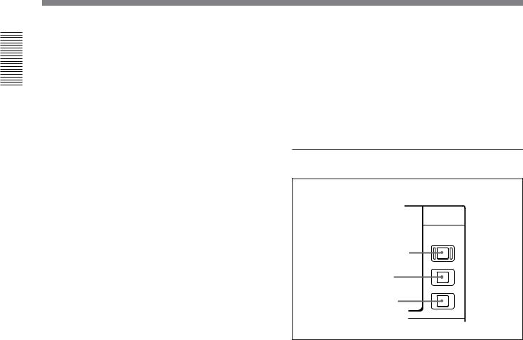
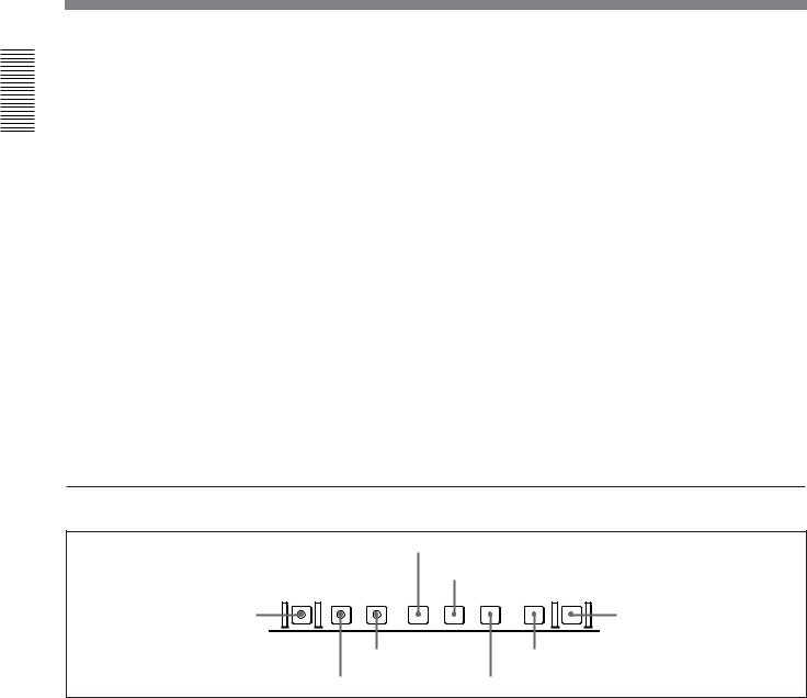
3 Remote control setting section
REMOTE
1 REMOTE button
9PIN
2 9PIN button
i.LINK
3 i.LINK button
1 REMOTE button
When remote-controlling this unit from the unit connected to the REMOTE-IN, REMOTE-OUT or i.LINK connector, press this button, turning it on.
2 9PIN button
When carrying out remote control between this unit and the unit connected to the REMOTE-IN or REMOTE-OUT connector, press this button, turning it on.
3 i.LINK button
When carrying out remote control between this unit and the unit connected to the i.LINK connector, press this button, turning it on.
16 Chapter 1 Overview
Lower Control Panel
1 METER FULL/FINE button
2 REC controls
3 PB controls
4MONITOR SELECT buttons
1Monitor/menu/display setting 2 Display section (see page 19) section (see page 18)
METER |
CH-1 |
CH-2 |
CH-3 |
CH-4 |
MONITOR SELECT |
|
|
|
|
|
|
|
|
|
||
|
|
|
|
|
|
|
|
|
ClipLink |
COUNTER |
|
|
|
|
SHUTTLE |
|
FULL/FINE |
|
|
|
|
L |
|
|
|
|
|
|
|
|
|||
|
|
|
|
|
|
|
LP |
U-BIT TC |
|
|
|
REPEAT |
JOG |
|||
|
|
|
|
|
CH-1 |
CH-2 CH-3 CH-4 |
|
VITC |
|
|
|
|
|
|||
|
|
|
|
|
|
|
|
|
|
NOT |
|
|||||
|
|
|
|
|
|
|
|
|
REC INHIBIT |
KEY INHIBIT |
SERVO |
|
|
|
EDITABLE |
|
PHONE LEVEL REC |
|
|
|
R |
|
|
|
HOURS |
MINUTES |
SECONDS |
FRAMES |
|
||||
PULL FOR VARIABLE |
|
|
|
|
|
|
|
|
|
|
|
|||||
|
|
|
|
|
LIST |
MARK |
PREREAD PB/EE PB |
MENU SET HOLD COUNTER SEL RESET |
CHANNEL CONDITION |
|
|
|||||
|
|
|
|
|
|
|
|
|
|
|||||||
|
PB |
|
|
|
- |
TRIM |
+ |
|
|
|
|
|
|
|
|
|
|
|
|
|
|
|
|
|
|
|
|
|
|
|
|
|
|
|
VIDEO |
INSERT |
CH-4 TC |
IN |
|
OUT |
|
|
|
|
|
PLAYER RECORDER |
|
|
||
|
CH-1 CH-2 |
CH-3 |
|
|
|
STANDBY |
PREROLL |
REC |
|
|
|
|
|
|
||
|
|
|
|
|
|
AUDIO |
|
EDIT |
|
|
|
|
|
|||
|
|
|
|
|
|
|
|
|
|
|
|
|
||||
|
ASSEMBLE |
DMC EDIT |
|
DELETE |
|
ENTRY SHIFT |
|
|
|
|
|
|
|
|
|
|
|
|
MEMORY |
|
|
|
|
|
|
|
|
|
|
|
|
||
HEADPHONES |
|
|
|
|
|
|
|
EJECT |
REW |
PLAY |
F FWD |
|
STOP |
|
|
|
|
|
|
|
|
|
|
|
|
|
|
|
|||||
|
|
PREVIEW AUTO |
EDIT REVIEW |
IN |
|
OUT |
|
|
|
|
|
SEARCH VARIABLE |
|
|
||
5Tape transport control |
6 Search control section |
|
section (see page 23) |
||
(see page 24) |
||
4 Editing control section (see page 22) |
||
6 PLAYER button and RECORDER button |
||
|
||
3 Edit mode setting section (see page 21) |
|
|
5 HEADPHONES jack and PHONE LEVEL control |
|
1 METER FULL/FINE button
This switches the display mode of the audio level meters in the upper control panel as follows:
FULL: In this mode the segment of the display corresponding to the current audio level and all lower segments light. A marker indicating the reference level (set with extended menu item 811) also appears.
FINE: The display is enlarged, with a step of 0.25 dB with respect to the reference level of 0 dB.
In this mode only the segment of the display corresponding to the current audio level lights. If the audio level exceeds the maximum display level, the top segment flashes, and if the audio level goes below the minimum display level, the bottom segment flashes.
2 REC (recording) controls
These individually adjust the recording levels on channels 1 to 4.
To set the recording level, put the unit in E-E mode, pull out the control knobs and adjust the level while watching the level meters.
When the control knobs are pushed in, the recording levels return to the preset levels and cannot be adjusted.
For details of selecting the E-E mode, see the description of the REC button in the tape transport control section (see page 23) and the PB/EE button in the monitor/menu/display setting section (see page 19).
3 PB (playback) controls
These adjust individually the playback levels on channels 1 to 4.
During playback, pull out the control knobs and adjust the level while watching the level meters.
When the control knobs are pushed in, the playback levels return to the preset levels, and cannot be adjusted.
Chapter 1 Overview 17
Overview 1 Chapter
Overview 1 Chapter
Location and Function of Parts
4 MONITOR SELECT buttons
There are four buttons CH-1 to CH-4 (channels 1 to 4) in each of the upper (L) and lower (R) rows. Use these buttons to select the channels for audio output via the HEADPHONES connector on the lower control panel and the MONITOR AUDIO connector on the connector panel.
The HEADPHONES connector outputs stereo sound (L and R) and the MONITOR AUDIO connector outputs monaural sound (L and R mixed).
You can select two or more channels in either row by pressing the buttons for the desired channels simultaneously. The sounds of the channels selected in the row are mixed.
In 2-channel audio recording mode (selected with extended menu item 818), it is possible to use the AUDIO OUT CH-3 and AUDIO OUT CH-4 connectors for monitor audio output for channels 1 and 2, respectively (use extended menu item 820).
5 HEADPHONES jack and PHONE LEVEL control
Connect stereo headphones with an impedance of 8 ohms to monitor the sound during recording, playback and editing.
The PHONE LEVEL control knob adjusts the volume.
6 PLAYER button and RECORDER button
When you carry out editing using a VCR connected to the REMOTE-IN or REMOTE-OUT connector as the player and this unit as the recorder, these buttons select which VCR the editing control buttons and tape transport buttons on this unit control.
PLAYER: The editing control buttons and tape transport buttons on this unit control the external player VCR.
RECORDER: The editing control buttons and tape transport buttons on this unit control the recorder (this unit).
When this unit is being used in standalone mode, neither button functions.
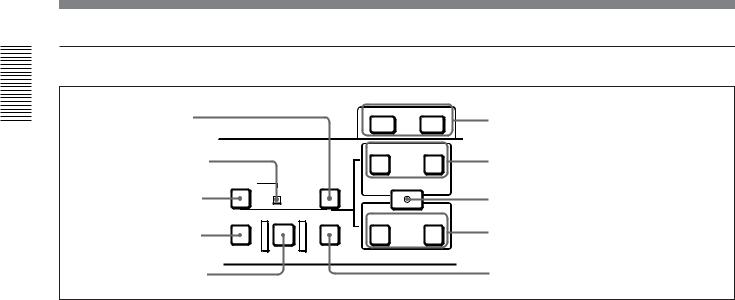
1 Monitor/menu/display setting section
2 MENU button
|
3 SET button |
PREREAD PB/EE PB MENU |
SET HOLD COUNTER SEL RESET |
1 PREREAD button |
4 RESET button |
6 PB button |
8 COUNTER SEL button |
5 PB/EE button |
7 HOLD button |
1 PREREAD button
When this is lit, a preread (read-before-write) is carried out in insert editing.
For details of preread editing, see the section “Preread Editing” (page 86).
2 MENU button
Use this button for setup menu operations.
Pressing this button, turning it on, shows setup menus in the time counter display (see page 20).
Press the button once more to exit from the menu display.
For details of setup menu operations, see Chapter 6 “Setup Menu” (page 105).
3 SET button
Use this button for setting time code and user bit values and in setup menu operations.
For details of setting time code and user bit values see Chapter 2 “Setting/Displaying Time Data and Text Information” (page 36).
18 Chapter 1 Overview
|
|
4 RESET button |
7 HOLD button |
To reset a time counter value (COUNTER) shown in the time counter display, press this button.
Resetting the COUNTER value erases all edit points. This button is also used for setting time code and user bit values and in setup menu operations.
5 PB/EE (playback/E-E) button
To select E-E mode input signals for the video/audio signals output during fast forward, rewind, still, and standby, press this button, turning it on.
Either one of this button and the PB button is always lit.
6 PB (playback) button
To select playback signals for the video/audio signals output during fast forward, rewind, still, and standby, press this button, turning it on.
Either one of this button and the PB/EE button is always lit.
To stop updating of the time code or user bit value in the time counter display (that is, to hold the display), press this button, turning it on. To set a time code or user bit value, first press this button to hold the value.
8 COUNTER SEL (select) button
This switches the value shown in the time counter display in the following sequence: COUNTER, TC, U- BIT.
|
Time counter display selection |
|
Selection |
|
Value displayed |
|
|
|
COUNTER |
|
Tape running time (hours, minutes, |
|
|
seconds, frames) |
|
|
|
TC |
|
Playback time code read by the internal |
|
|
time code reader or time code being |
|
|
recorded.a) |
U-BIT |
|
User bit value inserted in the playback time |
|
|
code or time code being recorded.a) |
a)The selection of TC or VITC is made by the TC SELECT switch on the subsidiary control panel.
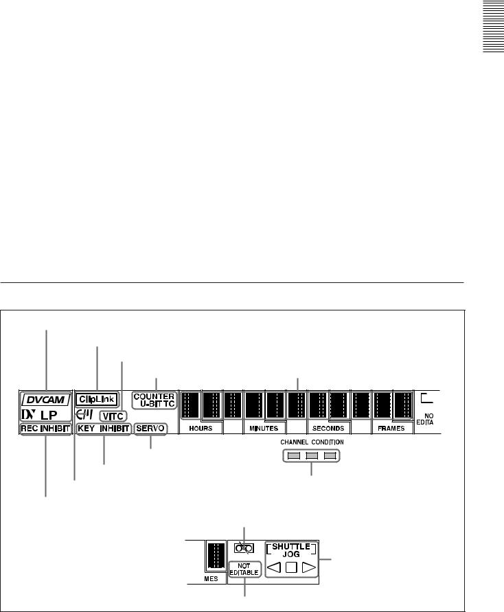
2 Display section
1 Recording/playback format indicators |
|
|
|
2 ClipLink indicator |
|
|
|
3 VITC indicator |
|
|
|
4 Time data type indicators |
5 Time counter display |
|
|
9 SERVO indicator |
|
|
|
8 KEY INHIBIT indicator |
|
|
|
7 Cassette memory indicator |
!º CHANNEL CONDITION indicator |
|
|
|
|
|
|
6 REC INHIBIT indicator |
|
|
|
!¡Tape end alarm indicator |
|
|
|
|
!™ SHUTTLE/JOG indicators |
|
|
!£ NOT EDITABLE indicator |
|
|
|
|
Chapter 1 |
Overview |
19 |
Overview 1 Chapter

Overview 1 Chapter
Location and Function of Parts
1 Recording/playback format indicators DVCAM: This lights when a tape recorded in
DVCAM format is played back.
DV: This lights when a tape recorded in consumer DV format is played back.
LP: This lights when a tape recorded in LP mode is played back.
When a tape recorded in DVCPRO (25) format or any other format than those mentioned above is played back, none of the above indicators lights.
2 ClipLink indicator
Lights when a cassette is loaded on which ClipLink log data is stored in the cassette memory.
For details of ClipLink log data, see Chapter 5 “ClipLink Operation” (page 95).
3 VITC indicator
Regardless of the data shown in the time counter display, this indicator lights when VITC in the signal played back or in the input video signal (in E-E mode) is being read.
4 Time data type indicators
One of the three indicators (COUNTER, U-BIT, and TC) lights to indicate the type of time data currently shown in the time counter display.
COUNTER: Count value of the time counter U-BIT: User bit data
TC: SMPTE time code (DSR-2000A) or EBU time code (DSR-2000AP)
5 Time counter display
Indicates the count value of the time counter, time code, or user bit data depending on the settings of the COUNTER SEL button in the monitor/menu/display setting section and the TC SELECT switch on the subsidiary control panel.
Also used to display edit point values, edit duration values, error messages and setup menu data.
6 REC (recording) INHIBIT indicator
This indicator is on or off according to the combination of the setting of the REC INHIBIT switch on the subsidiary control panel and the REC/SAVE switch on the loaded cassette, as shown in the following table. When this indicator is on, recording on tape is prohibited.
REC INHIBIT indicator indications
REC INHIBIT |
State of the REC/ |
REC INHIBIT |
switch position |
SAVE switch on |
indicator state |
|
the cassette |
|
|
|
|
ON |
SAVE/REC |
Lit |
|
|
|
OFF |
SAVE |
Lita) |
|
REC |
Off |
|
|
|
a)It is possible to make a setting (extended menu item 107) so that in this case the indicator flashes.
7 Cassette memory indicator
Lights when a cassette provided with a memory chip (“cassette memory”) is loaded.
8 KEY INHIBIT indicator
This indicator lights when the KEY INHIBIT switch on the subsidiary control panel is set to ON.
The buttons/switches to be operable even when this indicator is on can be determined using extended menu item 118.
9 SERVO indicator
When the drum servo and capstan servo are locked1), this indicator lights.
!º CHANNEL CONDITION indicator
This three-color indicator shows the state of the playback signal.
Green: The state of the playback signal is good. Yellow: The playback signal is somewhat
deteriorated, but playback is possible. Red: The playback signal is deteriorated.
When the red indicator remains on, head cleaning or an internal inspection is necessary.
.........................................................................................................................................................................................
1)Servo lock: This refers to the synchronization of the phase of the drum rotation and the reference signal for the tape transport position, so that the video heads can trace the same pattern on the tape for playback or recording.
20 Chapter 1 Overview
!¡ Tape end alarm indicator
Starts flashing when the remaining capacity of the tape is for about 2 minutes.
!™ SHUTTLE/JOG indicators
When searching in shuttle or variable mode using the search dial, the SHUTTLE indicator lights, and when searching in jog mode using the search dial, the JOG indicator lights. When the search dial is turned clockwise causing playback to take place in the forward direction, the · indicator lights. When the search dial is turned counterclockwise causing playback to take place in the reverse direction, the ª indicator lights. When the tape is stopped, the π indicator lights.
For more information about the search dial, see page 24.
!£ NOT EDITABLE indicator
Lights during playback of a tape that contains a recording in other than the DVCAM format. When this indicator is lit, the recordings contained in the tape can be used as source material for editing, but editing operations such as insert editing and assemble editing cannot be performed.
This indicator also lights when the audio recording mode selected on this unit does not coincides with that of the loaded tape.
3 Edit mode setting section
1 INSERT buttons
 INSERT
VIDEO CH-1 CH-2 CH-3 CH-4 TC
ASSEMBLE
2 ASSEMBLE button
1 INSERT buttons
Use these buttons to select the signals for insert editing1).
VIDEO: To select the video signal, press this button, turning it on.
CH-1 to CH-4 (channel 1 to channel 4): To select audio channels 1 to 4, press these buttons, turning them on. You can select any number of the channels.
TC: To select time code, press this button, turning it on.
2 ASSEMBLE button
Press this button, turning it on, to carry out assemble editing2).
All signals (video signals, audio signals, time code signals, and so forth) are recorded together.
Overview 1 Chapter
.........................................................................................................................................................................................
1)Insert editing: Editing in which new video/audio is added into the middle of existing recorded video/audio.
2)Assemble editing: Editing in which new video/audio is added in sequence to the end of existing recorded video/ audio.
Chapter 1 Overview 21
Overview 1 Chapter
Location and Function of Parts
4 Editing control section
1 DELETE button |
|
|
LIST |
MARK |
6 TRIM buttons |
|
|
|
- |
TRIM |
+ |
||
|
|
|
||||
2 MEMORY indicator |
|
|
IN |
|
OUT |
|
|
|
|
AUDIO |
|
7 AUDIO IN button and AUDIO OUT button |
|
|
DMC EDIT |
DELETE |
|
ENTRY SHIFT |
|
|
3 DMC EDIT button |
MEMORY |
|
|
|
|
8 ENTRY/SHIFT button |
|
|
|
|
|
||
|
PREVIEW AUTO EDIT |
REVIEW |
IN |
|
OUT |
|
4 PREVIEW button |
|
|
|
|
|
9 IN button and OUT button |
5 AUTO EDIT button |
|
|
|
|
|
!º REVIEW button |
1 DELETE button
This deletes an existing edit point.
Hold down this button and press the IN, OUT, AUDIO IN, or AUDIO OUT button which is lit, indicating an existing edit point. The button either goes off or flashes and the corresponding edit point is deleted. When the button flashes, it is necessary to set the deleted edit point again.
2 MEMORY indicator
When memorizing the playback speed using the DMC EDIT button, this indicator flashes as the playback speed is captured to memory, and lights continuously once the speed is captured.
3 DMC EDIT button
Use this button to memorize the playback speed varied between ±1 times normal speed and carry out automatic playback or automatic editing using the memorized playback speed.
For information about how to carry out DMC playback or DMC editing using this button, see the section “Dynamic Motion Control (DMC) Playback” (page 55) and “DMC Editing” (page 83), respectively.
4 PREVIEW button
After setting edit points, to preview the editing results before carrying out the edit, press this button, turning it on.
If the IN point is not set, the preview is carried out with the point where you pressed this button as the IN point.
During the preview the button is lit, and when the preview ends it flashes.
22 Chapter 1 Overview
5 AUTO (automatic) EDIT button
After setting edit points, to carry out automatic editing (recording), press this button, turning it on.
If the IN point is not set, the automatic editing is carried out with the point where you pressed this button as the IN point.
If you pressed the PREVIEW button to carry out a preview, when the preview ends this button flashes.
6 TRIM buttons
Use these buttons to trim an edit point to single-frame precision.
Hold down the IN, OUT, AUDIO IN, or AUDIO OUT button, and press one of these buttons. The MARK/+ button advances the corresponding edit point by one frame, and the LIST/− button sets it back by one frame.
During playback, pressing one of these buttons while holding down the PLAY button adjusts the tape speed by +8% or −8%, correspondingly. (Capstan override function)
These buttons are also used for ClipLink operations and setup menu operations.
For more information about ClipLink operations and setup menu operations, see Chapter 5 “ClipLink Operation” (page 95) and Chapter 6 “Setup Menu” (page 105), respectively.
7 AUDIO IN button and AUDIO OUT button
In insert editing, to set an audio IN point or audio OUT point separate from the corresponding video edit point, hold down the AUDIO IN button or AUDIO OUT button, and press the ENTRY/SHIFT button.
After you have made the setting, pressing the AUDIO IN button or AUDIO OUT button displays the audio IN point or audio OUT point set on the time counter display.
8 ENTRY/SHIFT button
Use this button for setting edit points, carrying out ClipLink operations, and so forth.
•To set a video IN point or OUT point: Hold down the IN button or OUT button, and press this button.
•To set an audio IN point or OUT point: Hold down the AUDIO IN button or AUDIO OUT button, and press this button.
For more information about ClipLink operation, see Chapter 5 “ClipLink Operation” (page 95).
9 IN button and OUT button
To set a video IN point or OUT point, hold down the IN button or OUT button, and press the ENTRY/ SHIFT button.
After you have made the setting, pressing the IN button or OUT button displays the IN point or OUT point on the time counter display.
!º REVIEW button
Use this button to carry out a review of the editing results after carrying out automatic editing.
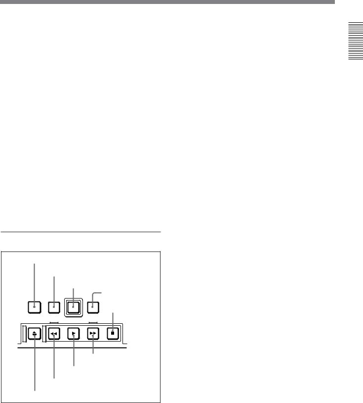
5 Tape transport control section
1 STANDBY button
2 PREROLL button
|
|
3 REC button |
|
|
4 EDIT button |
STANDBY |
PREROLL |
REC |
EDIT |
||
|
|
5 STOP button |
EJECT |
REW |
PLAY F FWD STOP |
9 F FWD button
8 PLAY button
7 REW button
6 EJECT button
1 STANDBY button
When a cassette is inserted and this button is off, to put the VCR in standby mode, press the button, turning it on.
In standby mode, the drum is rotating and the tape is in contact with the drum. As a result, recording or playback can start immediately.
To end standby mode, press the STANDBY button, turning it off.
If a certain period of time (value can be varied using extended menu item 501) elapse in standby mode, the unit automatically switches out of standby mode to protect the tape.
2 PREROLL button
Press this button to cue up to the preroll point (before the IN point by the time set as the preroll time) on the tape. You can change or select the preroll time and the state of the unit at the end of preroll (stop mode1) or still playback mode) using basic menu item 001 and extended menu item 401.
Cuing up to edit points
Hold down the IN, OUT, AUDIO IN, or AUDIO OUT button while pressing this button to cue up to the corresponding edit point.
3 REC (record) button
To start recording, press this button together with the PLAY button, turning it on.
Monitoring in E-E mode
When the unit is in stop mode, pressing this button lights it, and you can monitor the video and audio in E- E mode. To return to the original state, press the STOP button.
During playback, search, fast forward, or rewind, holding down this button allows you to monitor the video and audio in E-E mode. In this case the button does not light.
Overview 1 Chapter
.........................................................................................................................................................................................
1)Stop mode: the state in which the device currently the subject of operation is stopped, and the STOP button is lit.
Chapter 1 Overview 23

Overview 1 Chapter
Location and Function of Parts
4 EDIT button
To carry out manual editing, press this button simultaneously with the PLAY button.
Monitoring in E-E mode
When the unit is in stop mode, pressing this button lights it, and you can monitor the input signal selected with the ASSEMBLE button or INSERT buttons in E- E mode. To return to the original state, press the STOP button. During playback, search, fast forward, or rewind, holding down this button allows you to monitor the video in E-E mode.
5 STOP button
To stop recording or playback, press this button, turning it on.
When you stop playback, the unit switches either to still playback or to E-E mode according to setup menu settings, and the settings of the PB/EE button and PB button.
Fault display function
This button flashes when there is no external reference signal input or the input external reference signal is not synchronized to the input video signal. (See the description of extended menu item 105.)
6 EJECT button
To eject the cassette, press this button. While the cassette is being ejected, this button lights.
7 REW (rewind) button
To rewind the tape, press this button, turning it on.
8 PLAY button
To start playback, press this button, turning it on.
To operate in capstan override mode
Hold down this button, and turn the search dial.
For details of capstan override mode, see “3 Search dial” on this page.
9 F FWD (fast forward) button
To fast forward the tape, press this button, turning it on.
6 Search control section
SEARCH VARIABLE
3 Search dial
2 VARIABLE button
1 SEARCH button
1 SEARCH button
To use the search dial for playback in shuttle or jog mode, press this button, turning it on. Pressing the dial toggles between shuttle and jog modes. In shuttle mode, the SHUTTLE indicator in the display section lights, and in jog mode, the JOG indicator in the display section lights.
2 VARIABLE button
To use the search dial for playback in variable speed mode, press this button, turning it on. Pressing the dial toggles between variable speed mode and jog mode.
3 Search dial
Turn this to carry out playback in the modes shown in the following table. Turning the dial clockwise lights the · indicator in the display section and plays back in the forward direction. Turning the dial counterclockwise lights the ª indicator in the display section and plays back in the reverse direction. When the tape is stopped, the π indicator in the display section lights.
Pressing this dial toggles between shuttle mode and jog mode (or between variable mode and jog mode). When playing back in shuttle or variable mode, the SHUTTLE indicator in the display section lights, and when playing back in jog mode, the JOG indicator lights.
You can carry out noiseless playback in the range of ± 1 times normal speed.
24 Chapter 1 Overview

|
|
|
|
|
Playback modes using the search dial |
||
|
|
|
|
Playback |
|
Operations and functions |
|
mode |
|
|
|
|
|
|
|
Shuttle |
|
Press the SHUTTLE button or the search dial |
|
|
|
so that the SHUTTLE indicator in the display |
|
|
|
section lights, then turn the search dial. |
|
|
|
Playback is carried out at a speed determined |
|
|
|
by the position of the search dial. The |
|
|
|
maximum shuttle mode playback speed can be |
|
|
|
changed using extended menu item 102. |
|
|
|
|
|
Jog |
|
Press the SHUTTLE button or the search dial |
|
|
|
so that the JOG indicator in the display section |
|
|
|
lights, then turn the search dial. Playback is |
|
|
|
carried out at a speed determined by the speed |
|
|
|
of rotation of the search dial. The playback |
|
|
|
speed range is ±1 times normal speed. The |
|
|
|
search dial has no detents. |
|
|
|
|
|
Variable |
|
Press the VARIABLE button, turning it on, then |
|
speed |
|
turn the search dial. You can control the |
|
|
|
playback speed finely (61 steps) in the range of |
|
|
|
–1 to +2 times normal speed. |
|
|
|
The search dial has detents at the still position |
|
|
|
and at the normal speed position. |
|
|
|
The variable mode playback speed range can |
|
|
|
be changed using extended menu item 119. |
|
|
|
Noiseless playback is possible in the range of |
|
|
|
±1 times normal speed. |
|
Capstan |
|
Hold down the PLAY button and turn the |
|
override |
|
search dial to adjust the playback speed in the |
|
|
|
range of ±15%. Use this for phase adjustment |
|
|
|
between this unit and an external device |
|
|
|
connected to this unit. |
|
|
|
|
|
Changing the setting of extended menu item 101 enables you to select shuttle or jog mode just by turning the search dial without using the SEARCH or VARIABLE button.
Overview 1 Chapter
Chapter 1 Overview 25
Location and Function of Parts
Subsidiary Control Panel
Overview 1 Chapter
1 CHARACTER switch
|
|
|
|
|
|
|
2 CONTROL PANEL switch |
|
|
|
|||||||||
|
|
|
|
|
|
|
|
|
|
3 REC INHIBIT switch |
|
|
|
||||||
|
|
|
|
|
|
|
|
|
|
|
|
|
|
4 KEY INHIBIT switch |
|
|
|
||
|
|
|
|
|
|
|
|
|
|
|
|
|
|
|
|
5 PROCESS CONTROL switch |
|
||
|
|
|
|
|
|
|
|
|
|
|
|
|
|
|
|
|
|
|
|
|
|
|
|
|
|
|
|
|
|
|
|
|
|
|
|
PROCESS |
|
|
|
|
|
CHARACTER |
CONTROL |
PANEL |
REC INHIBIT |
KEY INHIBIT CONTROL PRESET |
PRESET |
PRESET |
|
||||||||||
|
|
OFF |
|
|
ON |
EXT |
|
INT |
ON |
|
|
OFF |
ON |
|
|
OFF |
MANUAL |
MANUAL |
MANUAL |
|
|
|
|
|
|
|
|
|
|
|
|
|
|
|
|
REMOTE LOCAL |
|
|
|
EXT |
INT |
|
|
|
|
|
|
|
|
|
|
|
|
REC |
FREE |
NDF |
DF |
OFF |
ON |
VITC |
TC |
|
|
|
|
|
RUN |
RUN |
|
|
|
|
||||||
REGEN |
PRESET |
TC GENERATOR |
|
|
VITC |
TC SELECT |
MENU |
VIDEO |
CHROMA |
SET UP |
||
|
|
|
|
|
|
|
|
|
|
|
||
!º TC SELECT switch !¡ VIDEO knob and PRESET/MANUAL switch
9 VITC switch
8 DF/NDF switch (DSR-2000A only)
7 FREE RUN/REC RUN switch
6 INT/EXT−PRESET/REGEN switch
!™ SET UP (DSR-2000A)/BLACK LEVEL (DSR-2000AP) |
|
|
|
!¢ Y/C DELAY knob and PRESET/MANUAL switch |
||||
knob and PRESET/MANUAL switch |
|
|
|
|
||||
!£ CHROMA knob and PRESET/MANUAL switch |
|
|
|
|
|
|
!∞ CHROMA PHASE (HUE) (DSR-2000A)/ |
|
|
|
|
|
|
|
|
|
CHROMA PHASE (DSR-2000AP) knob and |
|
|
|
|
|
|
|
|
PRESET/MANUAL switch |
PRESET |
PRESET |
|
PRESET |
PRESET |
PRESET |
|
!§ SYNC knob |
|
|
|
|
|
|
|
|
|
|
MANUAL |
MANUAL |
MANUAL |
MANUAL |
|
MANUAL |
|||
|
|
|
|
|
|
|
|
!¶ SC knob |
VIDEO |
CHROMA |
SET UP Y/C DELAY CHROMA PHASE SYNC SC |
||||||
|
|
|
|
|
|
(HUE) |
SYSTEM PHASE |
|
|
|
|
|
|
|
|
|
|
1 CHARACTER switch
Select whether or not to superimpose text information such as time code, menu settings, and alarm messages on the video signal output from the SDI OUTPUT 3 (SUPER) connector and VIDEO OUT 3 (SUPER) connector.
ON: Superimposed text OFF: No superimposed text
The factory default setting is ON.
2 CONTROL PANEL switch
Select the state of the control panel when this unit is operated.
INT: When operating this unit by its own control panel.
EXT: When operating this unit remotely by an optional control panel connected to the CONTROL PANEL connector.
The factory default setting is INT.
26 Chapter 1 Overview

3 REC (record) INHIBIT switch
When this switch is set to ON, the REC INHIBIT indicator in the display section lights, and recording on tape is no longer possible. (See the description of extended menu item 107.)
4 KEY INHIBIT switch
When this switch is set to ON, the KEY INHIBIT indicator in the display section lights, and the buttons in the upper control panel and lower control panel specified by the setting of extended menu item 118 are disabled.
5 PROCESS CONTROL switch
This selects the method of control of the internal digital video processor.
REMOTE: Select this position to use an optional remote control unit for remote control of the internal digital video processor.
MENU: Select this position to use the setup menu to change the settings for the internal digital video processor.
LOCAL: Select this position to use the subsidiary control panel to change the settings for the internal digital video processor.
6 INT/EXT–PRESET/REGEN (internal/external− preset/regenerated) switch
This switch is used to make selections relating to the time code and the internal time code generator.
(In this Operating Instructions, this switch may also be called simply as the INT/EXT switch or PRESET/ REGEN switch depending on the contents of the description in which the switch is referred to.)
|
Selection of internal/external time code |
|
Setting |
Time code used |
|
|
|
|
INT |
The time code produced by the internal time |
|
|
code generator |
|
|
By setting the switch to INT–REGEN or INT– |
|
|
PRESET, you can select “PRESET” or “REGEN” |
|
|
for the internal time code generator (see the |
|
|
next table). |
|
|
|
|
EXT |
The external time code selected as follows. |
|
|
• |
When the TC SELECT switch is set to TC |
|
|
The external time code input to the TIME |
|
|
CODE IN connector |
|
• |
When the TC SELECT switch is set to VITC |
|
|
The VITC time code included in the input |
|
|
video signal |
|
In this case, for the internal time code generator, |
|
|
“REGEN” is always selected (see the next |
|
|
table). |
|
|
|
|
Selection relating to the internal time code generator
Setting |
Operation of the internal time code generator |
|
|
PRESET |
The initial value of the time code produced by |
|
the internal time code generator can be preset |
|
by a control panel operation or by remote control |
|
from a device connected to the REMOTE-IN or |
|
REMOTE-OUT connector. |
|
|
REGEN |
The internal time code reader is synchronized to |
|
the playback time code read by the internal time |
|
code reader. |
|
|
7 FREE RUN/REC RUN switch
This switch selects the time code run mode of the internal time code generator.
FREE RUN: Regardless of the operating mode of this unit, the time code value advances continuously while the power is on.
REC RUN: The time code value advances only during recording. When this mode is selected, set the INT/EXT−PRESET/REGEN switch to INT− PRESET.
8 DF/NDF (drop-frame/non-drop-frame) switch
(for the DSR-2000A only)
This switch selects the mode of advancing the time code generator and time counter.
DF: Drop-frame mode NDF: Non-drop-frame mode
Note
When the PRESET/REGEN switch is set to REGEN, since the time code generator is synchronized to the playback time code, this switch has no effect.
9 VITC switch
To record the time code produced by the internal time code generator as a VITC, set this switch to ON. When this switch is set to OFF, internally generated time code is not recorded as VITC, but VITC present in the input video signal is recorded unchanged.
!º TC (time code) SELECT switch
This switch selects the time code, TC or VITC, shown in the time counter display.
Overview 1 Chapter
Chapter 1 Overview 27

Overview 1 Chapter
Location and Function of Parts
!¡ VIDEO knob and PRESET/MANUAL switch
The switch makes the selection described below. When it is set to MANUAL, you can use the knob to adjust the video signal output level.
PRESET: Regardless of the position of the knob, the video signal output level is set to the reference value.
MANUAL: You can adjust the video signal output level in the range ±3 dB.
You can change the adjustment range using extended menu item 714.
!™ SET UP (DSR-2000A)/BLACK LEVEL (DSR-
2000AP) knob and PRESET/MANUAL switch
The switch makes the selection described below. When it is set to MANUAL, you can use the knob to adjust the (black) setup level (DSR-2000A) or black level (DSR-2000AP).
PRESET: Regardless of the position of the knob, the setup level (DSR-2000A) or black level (DSR2000AP) is set to the reference value.
MANUAL: You can adjust the setup level (DSR2000A) in the range ±30 IRE1), or the black level (DSR-2000AP) in the range ±210 mV.
!£ CHROMA (chrominance) knob and PRESET/
MANUAL switch
The switch makes the selection described below. When it is set to MANUAL, you can use the knob to adjust the chrominance signal output level.
PRESET: Regardless of the position of the knob, the chrominance signal output level is set to the reference value.
MANUAL: You can adjust the chrominance signal output level in the range ±3 dB.
You can change the adjustment range using extended menu item 714.
!¢ Y/C DELAY knob and PRESET/MANUAL switch
The switch makes the selection described below. When it is set to MANUAL, you can use the knob to adjust the Y/C delay.
PRESET: Regardless of the position of the knob, the Y/C delay is set to the reference value.
MANUAL: You can adjust the Y/C delay in the range ±100 ns.
!∞ CHROMA PHASE (HUE) (DSR-2000A)/
CHROMA PHASE (DSR-2000AP) knob and PRESET/MANUAL switch
The switch makes the selection described below. When it is set to MANUAL, you can use the knob to adjust the hue/chrominance phase (the phase difference from a burst signal).
PRESET: Regardless of the position of the knob, the hue/chrominance phase is set to the reference value.
MANUAL: You can adjust the hue/chrominance phase in the range ±30°.
!§ SYNC knob
This adjusts the output signal sync phase with respect
to the input reference signal to this unit in the range ±3s.
Use this adjustment when the output phase of this unit is not accurately aligned with the reference signal phase, or when carrying out special effects editing with this unit and other VCRs connected to a switcher or other equipment.
!¶ SC (subcarrier) knob
This adjusts the output signal subcarrier phase with respect to the input reference signal to this unit in the range ±180°.
For editing with composite signals, use this adjustment when the output phase of this unit with respect to the phase of the reference signal is not accurately aligned with the subcarrier phase.
Note
The color of video on monitors connected to the composite and S-video outputs may temporarily change or be reversed when you rotate the SYNC and SC knobs.
.........................................................................................................................................................................................
1) IRE: A unit for representing a video level laid down by |
the IEEE (Institute of Electrical and Electronic |
the IRE (Institute of Radio Engineers). The IRE is now |
Engineers). |
28 Chapter 1 Overview
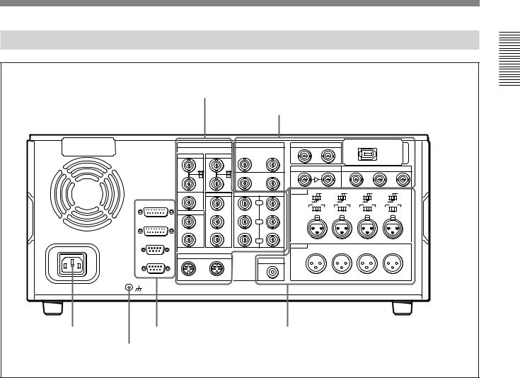
Connector Panel
1 Analog video input/output section (see page 30)
2 Digital input/output section (see page 31)
|
|
ANALOG VIDEO I/O |
DIGITAL AUDIO I/O(AES/EBU) |
SDTI(QSDI) |
|
i.LINK |
|
|
|
||||||
|
|
|
|
|
|
|
INPUT |
OUTPUT |
|
|
|
|
|
|
|
|
|
REF.VIDEO |
VIDEO IN |
CH-1/2 |
IN |
CH-3/4 |
|
|
|
|
|
|
|
|
|
|
|
IN |
|
|
|
|
|
|
|
|
|
|
|
|
|
|
|
75Ω |
|
75Ω |
|
|
SDI INPUT |
|
SDI OUTPUT |
|
|
||||
|
|
ON |
|
ON |
|
|
|
|
|
||||||
|
|
|
|
CH-1/2 |
OUT |
CH-3/4 |
|
|
|
|
1 |
2 |
|
3 |
|
|
|
OFF |
|
OFF |
|
|
|
|
|
|
|
|
|
|
|
|
|
|
|
|
|
|
|
|
|
|
|
|
(SUPER) |
|
|
|
|
|
VIDEO OUT |
COMPONENT VIDEO |
AUDIO IN |
LEVEL |
LEVEL |
LEVEL |
|
LEVEL |
|
||||
|
|
|
LOW |
HIGH LOW |
HIGH LOW |
HIGH LOW |
HIGH |
||||||||
|
|
OUT |
1 |
IN |
OUT |
|
OFF |
|
ON-600Ω OFF |
|
ON-600Ω OFF |
ON-600Ω OFF |
ON-600Ω |
||
|
VIDEO CONTROL |
|
|
|
Y |
|
|
|
|||||||
|
|
|
|
|
|
|
0dBm |
0dBm |
0dBm |
|
0dBm |
|
|||
|
|
|
|
|
|
|
-6dBm |
|
+4dBm -6dBm |
|
+4dBm -6dBm |
+4dBm -6dBm |
+4dBm |
||
|
|
TIME CODE |
|
|
|
|
|
|
|
|
|
|
|
|
|
|
|
IN |
2 |
|
|
|
CH-1 |
|
CH-2 |
|
CH-3 |
|
CH-4 |
|
|
|
CONTROL PANEL |
|
|
|
R-Y |
|
|
|
|
|
|
|
|
|
|
|
|
|
(SUPER) |
|
|
|
|
|
|
|
|
|
|
|
|
|
|
OUT |
3 |
|
|
|
|
|
|
|
|
|
|
|
|
~AC IN |
REMOTE-IN |
|
|
|
B-Y |
|
|
|
|
|
|
|
|
|
|
|
|
|
|
|
|
|
AUDIO OUT |
|
|
|
|
|
|
|
|
|
|
|
|
|
|
|
CH-1 |
|
CH-2 |
|
CH-3 |
|
CH-4 |
|
|
|
|
S VIDEO |
|
|
|
|
|
|
|
|
|
|
|
|
|
|
REMOTE-OUT |
IN |
OUT |
|
MONITOR AUDIO |
|
|
|
|
|
|
|
|
|
|
|
|
|
|
|
|
|
|
|
|
|
|
|
|
||
1 AC IN |
3 External device connectors |
4 Analog audio input/output section (see page 33) |
connector |
(see page 32) |
|
|
2 Ground terminal |
|
1 AC IN connector
Use the optional power cord to connect this to an AC outlet.
2 Ground terminal
Connect this to ground.
Overview 1 Chapter
Chapter 1 Overview 29
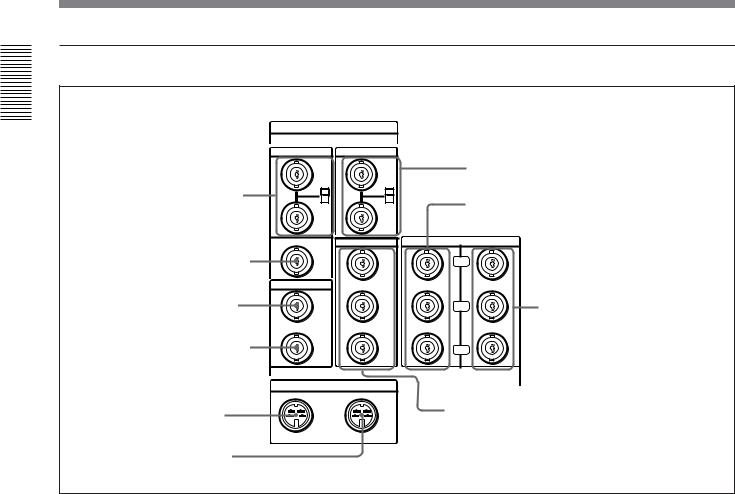
Location and Function of Parts
1 Analog video input/output section
Overview 1 Chapter
ANALOG VIDEO I/O
1REF. VIDEO IN connectors and 75Ω termination switch
2 REF. VIDEO OUT connector
3 TIME CODE IN connector
4 TIME CODE OUT connector
5 S VIDEO IN connector
6 S VIDEO OUT connector
REF.VIDEO |
VIDEO IN |
|
|
|
IN |
|
|
7 VIDEO IN connectors and 75Ω termination |
|
75Ω |
75Ω |
|
||
ON |
ON |
|
switch |
|
OFF |
OFF |
|
8 COMPONENT VIDEO Y/R−Y/B−Y IN |
|
|
|
|
connectors |
|
|
VIDEO OUT |
|
COMPONENT VIDEO |
|
OUT |
1 |
IN |
OUT |
|
|
|
|
Y |
|
TIME CODE |
|
|
|
|
IN |
2 |
|
|
|
|
|
|
R-Y |
9 COMPONENT VIDEO Y/R−Y/ |
|
(SUPER) |
|
|
B−Y OUT connectors |
|
|
|
|
|
OUT |
3 |
|
|
|
|
|
|
B-Y |
|
S VIDEO |
|
|
|
|
IN |
OUT |
|
!º VIDEO OUT 1, 2, and 3 (SUPER) connectors |
|
|
|
|
||
1 REF. (reference) VIDEO IN connectors (BNC type) and 75Ω termination switch
Input a reference video signal to one of these connectors. The two connectors can be used for a loopthrough connection. When making a loop-through connection, set the termination switch to OFF, and when not, set the switch to ON.
2 REF. (reference) VIDEO OUT connector (BNC type)
This connector outputs a reference video signal, except when i.LINK is selected in the input selection section
(see page 15).
3 TIME CODE IN connector (BNC type)
Input SMPTE time code (DSR-2000A) or EBU time code (DSR-2000AP) externally generated to this connector.
4 TIME CODE OUT connector (BNC type)
This connector outputs a time code according to the operating state of the unit, as follows:
30 Chapter 1 Overview
During playback: the playback time code During recording: the time code generated by the
internal time code generator or the time code input to the TIME CODE IN connector.
For more information about the time code output during recording, see extended setup menu item 611.
5 S VIDEO IN connector (4-pin)
Input an S-video signal with separated Y (luminance) and C (chroma: 3.58 MHz for DSR-2000A or 4.43 MHz for DSR-2000AP) components to this connector.
6 S VIDEO OUT connector (4-pin)
This connector outputs an S-video signal with separated Y (luminance) and C (chroma: 3.58 MHz for DSR-2000A or 4.43 MHz for DSR-2000AP) components.
7 VIDEO IN connectors (BNC type) and 75Ω termination switch
Input an analog composite video signal to one of these connectors. The two connectors can be used for a loopthrough connection. When making a loop-through connection, set the 75Ω termination switch to OFF and when not, set the switch to ON.
 Loading...