


3-858-739-15 (1)
Digital Video
Cassette Recorder
Operating Instructions page 2 EN |
EN |
|
Mode d’emploi page 2 F |
|
|
F |
||
|
DSR-30
DSR-30P
1996 by Sony Corporation

For DSR-30
WARNING
To prevent fire or shock hazard, do not expose the unit to rain or moisture.
CAUTION
RISK OF ELECTRIC SHOCK
DO NOT OPEN
CAUTION : TO REDUCE THE RISK OF ELECTRIC SHOCK,
DO NOT REMOVE COVER (OR BACK).
NO USER-SERVICEABLE PARTS INSIDE.
REFER SERVICING TO QUALIFIED SERVICE PERSONNEL.
This symbol is intended to alert the user to the presence of uninsulated “dangerous voltage” within the product’s enclosure that may be of sufficient magnitude to constitute a risk of electric shock to persons.
This symbol is intended to alert the user to the presence of important operating and maintenance (servicing) instructions in the literature accompanying the appliance.
CAUTION
You are cautioned that any changes or modifications not expressly approved in this manual could void your authority to operate this equipment.
Note
This equipment has been tested and found to comply with the limits for a Class B digital device, pursuant to Part 15 of the FCC Rules. These limits are designed to provide reasonable protection against harmful interference in a residential installation. This equipment generates, uses, and can radiate radio frequency energy and, if not installed and used in accordance with the instructions, may cause harmful interference to radio communications. However, there is no guarantee that interference will not occur in a particular installation. If this equipment does cause harmful interference to radio or television reception, which can be determined by turning the equipment off and on, the user is encouraged to try to correct the interference by one or more of the following measures:
•Reorient or relocate the receiving antenna.
•Increase the separation between the equipment and receiver.
•Connect the equipment into an outlet on a circuit different from that to which the receiver is connected.
•Consult the dealer or an experienced radio/TV technician for help.
Precautions
Safety
•Operate the unit only on 120 V AC, 60 Hz .
•If anything falls into the cabinet, unplug the unit and have it checked by qualified personnel before operating it any further.
•Unplug the unit from the wall outlet if you do not intend to use it for an extended period of time. To disconnect the cord, pull it out by the plug, never by the cord.
Installing
•Allow adequate air circulation to prevent internal heat buildup.
•Do not place the unit on surfaces (rugs, blankets, etc.) or near materials (curtains, draperies) that may block the ventilation slots.
•Do not install the unit near heat sources such as radiators or air ducts, or in a place subject to direct sunlight, excessive dust, mechanical vibration or shock.
•Do not install the unit in an inclined position. It is designed to be operated in a horizontal position only.
•Keep the unit and cassettes away from equipment with strong magnets, such as microwave ovens or large loudspeakers.
•Do not place heavy objects on the unit.
•If the unit is brought directly from a cold to a warm location, moisture may condense inside the VCR and cause damage to the video head and tape. When you first install the unit, or when you move it from a cold to a warm location, wait for about one hour before operating the unit.
Information
Compatible color systems
The DSR-30 is designed to record and play back using the NTSC color system. Recording of video sources based on other color systems cannot be guaranteed.
Caution
Television programs, films, video tapes and other materials may be copyrighted. Unauthorized recording of such material may be contrary to the provisions of the copyright laws. Also, use of this recorder with cable television transmission may require authorization from the cable television transmission and/or program owner.
Owner’s record
The model number is located at the rear and front of the unit and the serial number on the top. Record the serial number in the space provided below. Refer to these numbers whenever you call upon your Sony dealer regarding this product.
Model No. DSR-30 Serial No. ______________________
2 EN |
Introduction |
|
|

For DSR-30P
WARNING
To prevent fire or shock hazard, do not expose the unit to rain or moisture.
To avoid electrical shock, do not open the cabinet. Refer servicing to qualified personnel only.
Precautions
Safety
•This unit operates on 220 – 240 V AC, 50 Hz. Check that the unit’s operating voltage is identical with your local power supply.
•If anything falls into the cabinet, unplug the unit and have it checked by qualified personnel before operating it any further.
•The unit is not disconnected from the mains as long as it is connected to the mains outlet, even if the unit itself has been turned off.
•Unplug the unit from the wall outlet if you do not intend to use it for an extended period of time. To disconnect the cord, pull it out by the plug, never by the cord.
Installing
•This unit is equipped with a fan at the rear. Do not insert objects nor touch the fan during operation.
•To prevent internal heat buildup, install the unit at least 5 cm away from the wall, and dust the unit periodically.
•Do not place the unit on surfaces (rugs, blankets, etc.) or near materials (curtains, draperies) that may block the ventilation slots.
•Do not install the unit near heat sources such as radiators or air ducts, or in a place subject to direct sunlight, excessive dust, mechanical vibration or shock.
•Do not install the unit in an inclined position. It is designed to be operated in a horizontal position only.
•Keep the unit and cassettes away from equipment with strong magnets, such as microwave ovens or large loudspeakers.
•Do not place heavy objects on the unit.
•If the unit is brought directly from a cold to a warm location, moisture may condense inside the VCR and cause damage to the video head and tape. When you first install the unit, or when you move it from a cold to a warm location, wait for one to two hours before operating the unit.
Compatible colour systems
The DSR-30P is designed to record and play back using the PAL colour system. Recording of video sources based on other colour systems cannot be guaranteed.
Caution
Television programmes, films, video tapes and other materials may be copyrighted. Unauthorised recording of such material may be contrary to the provisions of the copyright laws. Also, use of this recorder with cable television transmission may require authorisation from the cable television transmitter and/ or programme owner.
For the customers in the Netherlands
Voor de klanten in Nederland
Bij dit produkt zijn batterijen geleverd. Wanneer deze leeg zijn, moet u ze niet weggooien maar inleveren als KCA.
EN
Introduction |
3 EN |
|
|
4 EN |
Introduction |
|
|

Table of contents
Introduction
6Notes on video cassettes
7Notes on recording/playback
Index to Parts and Controls
8 Main unit
15 Remote commander
Getting Started
18MENU chart
19Setting the clock
20Changing menu options
23Adjusting the picture color (Y/C delay)
24Erasing the cassette memory
Playback
25 Playing at various speeds
27 Searching using the index function
29Displaying tape information
30Watching wide pictures
31Auto Repeat
32One Program Play
Recording
33AC timer recording
34Setting the timer (DSR-30P only)
35Checking/changing/cancelling timer settings (DSR-30P only)
Editing
36 Editing methods
39 Connections and preparation
41Synchronized editing
42Duplicate
43Assemble editing
45 Video/audio insert
50 Connecting other equipment
|
Additional Information |
51 |
Precautions |
54 |
Troubleshooting |
57Specifications
58Compatibility of DVCAM and DV format
60Warning and notice messages
61Index
Introduction |
5 EN |
|
|

Notes on video cassetes
Usable cassettes
Use Standard-DVCAM cassettes or Mini-DVCAM cassettes with this VCR.
PDV-184ME can record programs for 184 minutes and PDVM-40ME can record for 40 minutes. You can get the highest quality pictures with this digital video cassette recorder using DVCAM cassettes. You may not be able to get as good quality with other cassettes. We recommend using DVCAM cassettes so that you can record your one-time events in highest quality.
|
|
|
|
|
|
|
|
|
|
|
|
|
|
|
|
|
|
|
|
|
|
|
|
|
|
|
|
|
|
|
|
Standard DVCAM cassette |
|
|
|
Mini DVCAM cassette |
|||||||||||
Cassette memory
Cassette memory is an optional feature that is mounted on some Standard DVCAM cassettes and Mini DVCAM cassettes. When you record a program, the recording date and time, and the programs’ position on the tape are stored in the cassette memory so that you can quickly locate the program later on. indicates that you can use the cassettes 16 kbits of data can be stored on. On this VCR, you can use the cassettes up to 16 kbits of data can be mounted on.
To save a recording
To prevent accidental erasure of a recording, slide in the safety switch on the cassette so that the red portion becomes visible. To record on a tape, slide out the switch so that the red portion is hidden.
Write Protected Write Enabled
Notes
•You cannot play back a DVCAM tape recorded in other color systems on this VCR.
• , , and
6 EN |
Introduction |
|
|

Notes on recording/ playback
Copyright precautions
On recording
You cannot record any software having copyright protection signals on this VCR. If you start recording protected video and audio signals, a warning message appears on the monitor screen and the VCR stops recording.
For DSR-30P only: If you record a programme using timer, that is encoded with copyright protection signals, the VCR will continue recording but the video and audio signals will not be recorded on tape.
On playback
When you play back software having copyright protection signals on this VCR, you may not be able to copy it onto other equipment.
Limitations caused by the difference in format
This VCR can record, play back and edit the tapes recorded in DVCAM format. It can also play back the tapes recorded in DV format (SP mode). However, due to the difference in format, you may not be able to record or edit some tapes affected by recording conditions of the tape (e.g., A tape originally recorded in DV format is dubbed in DVCAM format.)
For details, refer to “Compatibility of DVCAM and DV format” on page 58.
No compensation for contents of the recording
Contents of the recording cannot be compensated for if recording or playback is not made due to a malfunction of the VCR, video tape, etc.
Introduction |
7 EN |
|
|
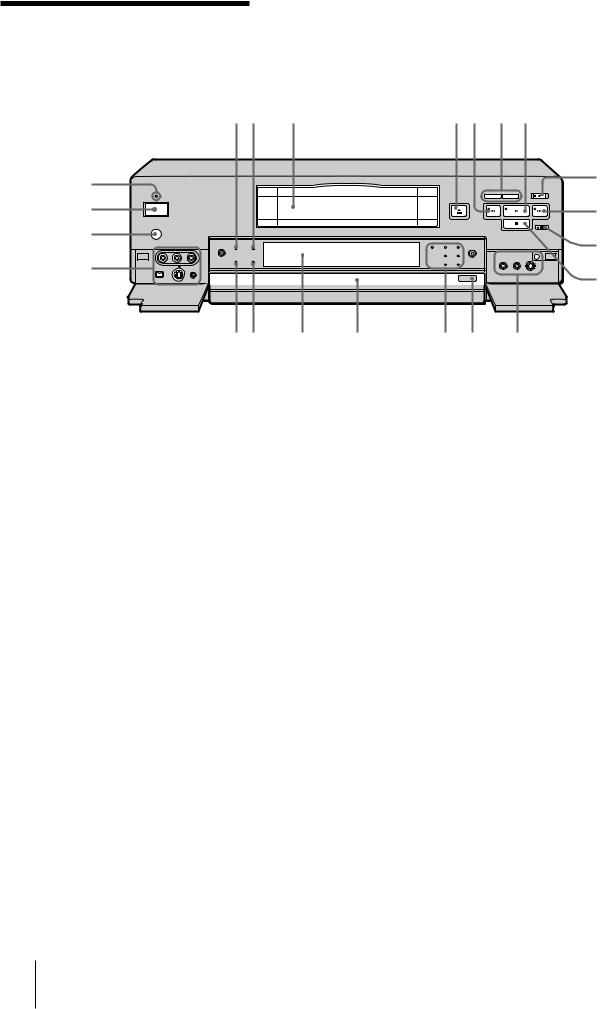
Main unit
Front panel
@™ @¡ @º
!ª
Refer to the pages indicated in ( ) for details.
12 3 |
|
|
4 5 6 7 |
|
|
|
|
|
8 |
|
|
|
|
9 |
|
|
|
|
!º |
|
|
|
|
!¡ |
!• !¶ |
!§ |
!° |
!¢ !£ |
!™ |
1NS AUDIO indicator
Lights when the VCR plays back a tape whose audio recording was made in the unlock mode, or when unlock mode signals are input through the DV terminals.
For details, see “Compatibility of DVCAM and DV format” on page 58.
2DVCAM indicator
Lights when the VCR records in DVCAM format or plays back a tape recorded in DVCAM format.
3 Cassette compartment
4 6 EJECT button
5 0 REW button
6COUNTER SELECT/RESET buttons (14)
Press to switch the counter in the order of time code, remaining time and tape counter. Press RESET to reset the counter to “0:00:00 (0H00M00S).”
7 ( PLAY button
8r REC button
To set the VCR to recording pause mode, press r while keeping Ppressed. You cannot set it to recording pause mode by pressing ron the operation panel or the Remote Commander.
9 ) FF button
!º P PAUSE button
!¡ p STOP button
!™ See section A on page 9.
!£ OPERATION PANEL OPEN/CLOSE button (10)
!¢ See section B on page 9.
!° Operation panel
!§ Display window
!¶ DF indicator (DSR-30 only)
Lights when the VCR plays back a tape whose time code is recorded in drop frame mode or when the VCR records a program in drop frame mode, setting the TIME CODE in the SET UP MENU to “DF”.
!• WIDE indicator (30)
Lights when the VCR plays back a tape which the wide screen signals are recorded on or when it detects input of WSS signals from the LINE-1 IN, LINE-2 IN jacks or DV IN/OUT jack.
!ª See section C on page 9.
@º Remote sensor
@¡ POWER switch
@™ ON/STANDBY indicator
Lights green when the power is on. When the power is off, the indicator lights red (DSR-30P) or goes off (DSR-30).
8 EN Index to Parts and Controls

A |
1 2 3 |
C |
1 |
||
|
|
|
|
|
|
|
|
|
|
|
|
4
1MIC (PLUG IN POWER) jack
Connect a microphone with a miniplug.
2 PHONES jack
3 CL button (54)
4 PHONES LEVEL (headphones volume level) control
B1 2 3
7 6 5 4
1H(function lock) indicator
Lights when the FUNCTION LOCK switch at the rear is set to “ON.”
2EXT. TIMER REC indicator (33)
Lights when the EXTERNAL TIMER switch at the rear is set to “REC.”
3STEREO indicator
Lights when the VCR is in the stereo mode.
4MAIN/L (main/left) indicator
Lights when the VCR is set to listen to the main sound of a bilingual mode or L-channel sound of the stereo mode.
5SUB/R (sub/right) indicator
Lights when the VCR is set to listen to the sub sound of a bilingual mode or R-channel sound of the stereo mode.
6ONE PGM (program) PLAY indicator (32)
Lights when the VCR plays back a tape in One Program Play mode.
7AUTO REPEAT indicator (31)
Lights when the EXTERNAL TIMER switch at the rear panel is set to “PB [AUTO REPEAT].”
43 2
1 LINE-2 IN audio/video input jack (39)
2 lLANC jack (38, 39)
3 LINE-2 IN S VIDEO input jack (39)
4DV IN/OUT jack (39)
Use when the equipment connected to the VCR has a DV jack.
If you connect the VCR and the other equipment using DV jacks and the LANC jacks, you can minimize deterioration of picture quality during dubbing, editing or capturing still pictures into a personal computer (IBM PC/AT compatible) by digital processing. For details, refer to the instruction manual of the equipment you use.
(continued)
Index to Parts and Controls |
9 EN |
|
|

Main unit (continued)
Operation panel
12 34 567
|
8 |
!° |
9 |
|
|
|
!º |
!¢ |
!¡ |
|
|
|
!™ |
!£ |
|
1 See section D on page 11.
2 See section E on page 11.
3 PCM MODE indicators (49)
4 See section F on page 11.
5 ( (play) button
6 p (stop) button
7 P (pause) button
8PLAYER button (43)
When you connect another VCR to the LANC jack, press this button so that you can control the other VCR.
9RECORDER button (41)
When you connect another VCR to the LANC jack, press this button so that you can control this VCR.
0Shuttle ring (25)
During playback or pause, use this ring to play back
the picture at various speeds. Select the speed you want from among 1/5 (slow), 1, ×2, 10 and 15 (18 for
DSR-30P.)
!¡ Jog dial (25)
During pause, use this dial to play back or search the picture at various speeds. The playback speed changes according to the speed you turn the dial at.
!™ MARK button (43)
!£ r REC button
!¢ See section G on page 11.
!° COMMAND MODE selector (17)
Detaching the control panel
1Press OPERATION PANEL OPEN/CLOSE on the front panel.
2While pressing the buttons on both sides of the panel, slightly lift up and slide forward the panel.
Attaching the operation panel
1Push in the cord into the inner part of the panel tray.
2Set the panel into the attachment grooves, and push down until the panel clicks.
Groove
3 Press OPERATION PANEL OPEN/CLOSE.
10 EN Index to Parts and Controls
D 1 2
1MENU button (20)
2EXECUTE button (20)
3CURSOR (M/Â/µ/m) buttons (20)
3
E 1 |
3 |
2 
 4
4
1AUDIO MONITOR selector (40)
Use to select the audio track you want to hear (stereo 1, stereo 2 or mix) when playing pack a tape recorded in 12bit mode (Fs32k.)
2AUDIO MIX BALANCE control (40)
When playing back a tape recorded in 12bit mode (Fs32k.), use to adjust the audio balance between the stereo 1 and stereo 2 when you select “MIX.”
3REC BALANCE control (40)
Use to adjust the recording balance (normally, set it to center.)
4REC LEVEL control (40)
Use to adjust the recording level so that the red indicators of the level meter do not light up.
F 1 |
2 |
8


 3
3
7 |
4 |
|
5 |
||
|
||
6 |
|
1 VIDEO INSERT button (45)
2 STEREO 1 INSERT button (45)
3 STEREO 2 INSERT/AUDIO DUB button (45)
4ASSEMBLE button (43)
Press to enter assemble editting mode.
5EVENT BACK/FWD buttons (43)
Press to select each event in turn in order to change or check events.
6 START/PAUSE button (41)
7EDIT STANDBY button (41)
During synchronized editing, press to make this VCR enter the recording pause mode and make the other VCR enter the playback pause mode. To release the standby mode, press the button again.
8DUPLICATE W/TC button (42)
Use to duplicate a tape with its time code.
G 1 |
5 |
2 |
6 |
3 |
7 |
4 |
8 |
|
1ONE PGM PLAY button (32)
Use to play One Program Play on this VCR without connecting an external switch.
2INPUT SELECT button (33)
Select input from the LINE-1 IN, LINE-2 IN jacks or DV IN/OUT jack.
3DISPLAY button (14)
Press to display counter information on the monitor screen.
4SEARCH SELECT button, indicators and =/+ buttons (27)
5AU (audio) MONITOR MAIN/L, SUB/R button
When playing back a tape with bilingual sound or stereo sound, or listening to the sound input from the DV IN/OUT jack, press to select the sound you want.
Indicator |
To listen to |
|
|
Bilingual sound |
Stereo sound |
|
|
|
MAIN/L and |
Both main sound |
Stereo |
SUB/R or |
and sub sound |
|
STEREO |
|
|
|
|
|
MAIN/L |
Main sound |
Left channel only |
|
|
|
SUB/R |
Sub sound |
Right channel only |
|
|
|
6DATA CODE button
See “Displaying tape information” on page 29.
7 COUNTER RESET button (14)
8 COUNTER SELECT button (14)
Index to Parts and Controls |
11 EN |
|
|
Main unit (continued)
Rear panel
|
1 |
2 |
3 |
|
|
|
|||||||||
|
|
|
|
|
|
|
|
|
|
|
|
|
|
|
|
|
|
|
|
|
|
|
|
|
|
|
|
|
|
|
|
|
|
|
|
|
|
|
|
|
|
|
|
|
|
|
|
|
|
|
|
|
|
|
|
|
|
|
|
|
|
|
|
|
|
|
|
|
|
|
|
|
|
|
|
|
|
|
|
|
|
|
|
|
|
|
|
|
|
|
|
|
|
|
|
|
|
|
|
|
|
|
|
|
|
|
|
|
|
|
|
|
|
|
|
|
|
|
|
|
|
|
|
|
|
|
|
9 |
8 |
7 |
6 |
5 |
4 |
1ONE PGM PLAY TRIGGER jack (32)
For One Program Play, connect an external switch, etc.
2CONTROL S IN/OUT jacks
Connect a wired remote control unit so that you can operate a number of VCRs simultaneously.
3LINE-1 IN jack (39)
To connect a VCR equipped with the S VIDEO OUT jack, use the S VIDEO jack on this VCR.
4 ~ AC IN socket (31)
5LINE-2 OUT jack
To connect a VCR equipped with the S VIDEO IN jack, use the S VIDEO jack on this VCR.
6LINE-1 OUT jack
To connect a VCR equipped with the S VIDEO IN jack, use the S VIDEO jack on this VCR.
7 l LANC jack (38, 39)
8FUNCTION LOCK switch
To prevent an accidental operation, set the switch to “ON.” The buttons on the front panel and operation panel of the main unit will not work.
To lock the buttons on the remote commander and the CONTROL S IN/OUT jacks,
slide the COMMAND MODE selector on the operation panel of the main unit to “OFF’. You cannot lock the LANC jack.
9EXTERNAL TIMER selector
Use to select External Timer Recording or Auto Repeat.
To record using an external AC timer (33)
Set to “REC.” When AC power is supplied to this VCR, recording starts.
To play the VCR in Auto Repeat (AC-ON Repeat) mode (31)
Set to “PB [AUTO REPEAT]”. When AC power is supplied to this VCR, a tape rewinds to its beginning automatically and playback starts. When playback finishes, the tape rewinds to its beginning and playback starts again.
The points on the tape where playback stops, are the same as those in One Program Play.
12 EN Index to Parts and Controls
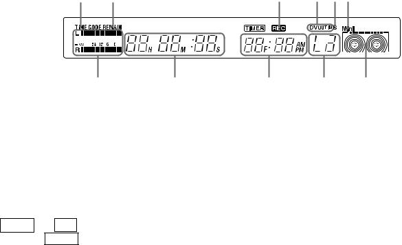
Display window
12
!¡ 0
1TIME CODE indicator
Lights when displaying the time code.
2REMAIN (remaining time) indicator
Lights when displaying the remaining time.
3REC (recording) indicator
Lights during recording, recording pause or external timer recording.
–DSR-30P only–
TIMER and REC light up during internal timer recording. TIMER lights up in the internal timer recording standby mode.
4DV OUT/IN indicator
When you select “DV” using INPUT SELECT , “DV IN” appears in the display window.
While digital signals are being output from the DV IN/OUT jack, “DV OUT” appears.
When you select “DV IN” and digital signals are output from the DV IN/OUT jack, “DV OUT IN” appears.
34 56
9 8 7
5S (S video) input indicator
Lights when you select “LINE 1” or “LINE 2” and the S VIDEO jack.
6Cassette type indicator
When you insert a Mini-DVCAM cassette or MiniDV cassette into the VCR, “Mini” appears.
7 Tape transport indicator
8 INPUT SELECT indicator
9 Current time/Frame indicator
0Tape counter indicator
See “How to check the display window” on page 14.
!¡ Peak level meter (40)
(continued)
Index to Parts and Controls |
13 EN |
|
|

Main unit (continued)
How to check the display window
Check the TIME CODE and Tape Counter
Each time you press COUNTER SELECT, the indications change as follows: “Time code” n“Remaining time” n “Tape counter”
(Illustration: DSP-30P)
Time code |
Remaining time + Current time |
Tape counter + Current time |
To reset the tape counter to “0H00M00S”
Press COUNTER RESET when tape counter is displayed. The counter resets to “0H00M00S” whenever a tape is reinserted.
Notes
•The counter stops counting when it comes to a portion with no recording.
•The counter indication may be inaccurate when a tape that has blank portions is rewound or fast-forwarded repeatedly.
•During fast-forward, rewind or search, the tape speed automatically adjusts to the remaining amount of tape. In these cases, the counter or time code indication may stop momentarily.
•Use the remaining time display as an approximate indication. The indication may be inaccurate depending on the tape type.
To see the indications on the monitor screen
Press DISPLAY.
Counter indications appear on the monitor screen. If you press the button again, the indications disappear from the screen.
About the tape transport indicator
During a tape loading |
Indicating the remaining |
Indicating tape tranport |
|
time |
direction and speed |
|
The beginning of the tape |
During playback m |
|
|
During fast forwarding mm |
|
|
During rewinding MM |
|
The end of the tape |
Turns according to the |
|
tape transport |
14 EN Index to Parts and Controls

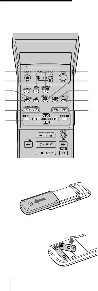
Remote commander
1
!§
!°
!¢
!£ !™ !¡
!º
9
The buttons on the remote commander work as the buttons on the main unit with the same name.
21 6EJECT button
2 COMMAND MODE selector (17)
3 POWER (ON/STANDBY) button
34 The buttons for monitor or TV operation
INPUT SELECT button Power button
VOL (volume) +/– buttons
CHANNEL +/– buttons
You can use these buttons for aSony monitor/TV
4with gmark.
5 r REC button
6 ) FF button
7 P PAUSE button
58 p STOP button
9 Shuttle ring (25)
6!º Jog dial (25)
7!¡ · PLAY button
8!™ 0 REW button
!£ SEARCH 3/# buttons (25)
!¢ CHANNEL +/– buttons
Use to select input jack.
!° AUDIO MONITOR buttons (11)
!§ TV/VCR buttons
Use to operate a VCR which has a built-in TV tuner.
(continued)
Index to Parts and Controls |
15 EN |
|
|
Remote commander
(continued)
Front with cover opened
!¡
!º
9
8
7
6
Inserting the batteries
1 Open the lid at the rear.
2 Insert two size AA (R6) batteries.
Match the + and – on the batteries to the diagram inside the battery compartment.
1 COUNTER SELECT button (14)
2 COUNTER RESET button (14)
3PRINT button
When you connect the LANC connectors of this VCR and a video printer, you can start printing by pressing this button. For details, see the instruction
1 manual of the video printer.
When you use this PRINT button, set the “LANC
2MODE” in the SET UP MENU to “S.”
4 SEARCH SELECT button (27)
35 SEARCH =/+ button (27)
46 Buttons for MENU operation (20)
MENU button
5CURSOR (?/>/.//) buttons EXECUTE button
7 FRAME '/7 buttons (26)
8 . SLOW button (26)
9 ×2 button (26)
!º DISPLAY button (14)
!¡ DATA CODE button (29)
Notes
•With normal use, the batteries should last for approximately three to six months.
•If you will not use the remote commander for an extended period, remove the batteries to avoid possible damage from battery leakage.
•Do not use a new battery with an old one.
•Do not use different types of batteries together.
16 EN Index to Parts and Controls
Setting the COMMAND MODE selector
Set COMMAND MODE on the remote commander to the same position as that on the VCR (both switches are set to “VTR4” at the factory.) Change the settings, however, in the following cases:
•If you use two or more Sony VCRs: Change the setting of each VCR in order to prevent accidental operation caused by overlapping of commander signals.
•To control another Sony VCR with the remote commander supplied with this VCR: Set COMMAND MODE on the other VCR to the same position as that on the remote commander supplied with this VCR.
•To control this VCR with the remote commander supplied with the other Sony VCR: Set COMMAND MODE on the remote commander supplied with the other VCR to the same position as that on this VCR.
Tips
•If you set the COMMAND MODE on the operation panel to “OFF,” you can no longer control this VCR from any other Sony remote commander.
•If the other Sony VCR does not have a COMMAND MODE switch, use the following settings:
VTR 1: For Sony Betamax format VCRs VTR 2: For Sony 8 mm format VCRs VTR 3: For Sony VHS format VCRs
To change the settings of COMMAND MODE on the remote commander
To change to VTR1 – VTR3
1 2 3
VTR
4 5 6
Set to the left.
To change to VTR4 – VTR6
1 2 3
VTR
4 5 6
Set to the right.
To change the settings of COMMAND MODE on the VCR
To change to VTR1 – VTR3
Set to the left.
Note
Setting of the COMMAND MODE selector works on the CONTROL S jack as well as the buttons on the remote commander.
OFF
14
2 5
5
36
To change to VTR4 – VTR6
Set to the right.
|
|
|
|
|
|
|
|
|
OFF |
|
|||
|
|
|
||||
|
|
|
|
|||
1 |
4 |
|||||
2 |
|
|
|
5 |
||
3 |
|
|
|
6 |
||
Index to Parts and Controls |
17 EN |
|
|
MENU chart
This VCR has various functions available, and you can set and check them on the monitor screen. To activate these functions, use the MENU buttons on the remote commander or control panel of the main unit.
Refer to the pages indicated in ( ) for details.
DSR-30
MENU
CLOCK SET
CASSETTE MEMORY ERASE
Y/C DELAY
SET UP MENU
SELECT |
: |
µ |
|
SET |
: |
EXECUTE |
|
DSR-30P
MENU
CLOCK SET
CASSETTE MEMORY ERASE
Y/C DELAY
SET UP MENU
TIMER SET CHECK
SELECT |
: |
µ |
|
SET |
: |
EXECUTE |
|
|
|
|
|
|
|
|
|
|
CLOCK SET |
|
|
|
|
||
|
|
|
|
|
|
|
|
|
|
1. 1. 1996 |
MON |
0:00 |
|
||
|
|
|
|
|
|
|
|
|
SELECT |
: |
Mm |
|
|
|
|
|
SET |
: |
µ |
|
|
|
|
|
END |
: |
EXECUTE |
|
|
||
|
|
|
|
|
|
|
|
(DSP-30P)
CASSETTE MEMORY ERASE
ALL DATA |
YES |
NO |
INDEX DATA |
YES |
NO |
DATE DATA |
YES |
NO |
PHOTO DATA |
YES |
NO |
SELECT |
: |
µ |
|
Mm |
|
|
SET |
: |
EXECUTE |
||||
CANCEL : |
MENU |
|
||||
Y/C DELAY
SET . PLAY OR DV INPUT
AND Mm
|
|
|
|
|
|
|
|
|
|
|
|
|
|
|
|
|
|
SET UP MENU |
|
|
|
|
|
|
PAGE 1 |
|
|||||||
|
|
|
|
|
|
|
|
|
|
|
|
|
|
|||
|
L1 IN VIDEO |
|
|
S |
|
NORM |
|
|||||||||
|
AUDIO MODE |
|
|
16 |
|
12 |
|
|||||||||
|
TIME CODE |
|
|
DF |
|
NDF |
|
|||||||||
|
CM SEARCH |
|
|
ON |
|
OFF |
|
|||||||||
|
LANC MODE |
|
|
M |
|
S |
|
|||||||||
|
SHUTTLE MODE |
A |
|
B |
|
|||||||||||
|
SELECT : |
|
|
|
|
|
|
|
|
|
|
|
||||
|
µ |
Mm |
|
|
|
|
||||||||||
|
|
|
|
|
|
|
|
|
|
|
|
|
|
|
|
|
|
|
|
|
|
|
|
|
|
|
|
|
|
|
|||
|
|
|
|
|
|
|
|
|
|
|
|
|||||
|
SET UP MENU |
|
|
|
|
|
|
PAGE 2 |
|
|||||||
|
|
|
|
|
|
|
|
|
|
|
|
|
|
|
|
|
|
WIDE PB |
|
|
|
|
|
|
|
|
ON |
|
|
OFF |
|
||
|
AUTO DISPLAY |
|
|
|
ON |
|
|
OFF |
|
|||||||
|
JOG WITH SOUND |
ON |
|
|
OFF |
|
||||||||||
|
BEEP |
|
|
|
|
|
|
|
|
|
ON |
|
|
OFF |
|
|
|
DIMMER |
|
|
|
|
|
|
|
|
ON |
|
|
OFF |
|
||
|
SELECT : |
|
|
|
|
|
|
|
|
|||||||
|
µ |
|
Mm |
|
|
|
|
|||||||||
|
|
|
|
|
|
|
|
|
|
|
|
|
|
|
|
|
|
|
|
|
|
|
|||||||||||
|
|
|
|
|
|
|||||||||||
|
TIMER |
SET/CHECK |
|
26. 12 THU |
|
|||||||||||
|
DATE |
|
|
|
START |
|
|
|
STOP |
|
LINE |
|||||
|
1. |
1 |
WED |
0:00 |
|
|
|
|
1:00 |
1 |
|
|||||
|
31. |
12 |
TUE |
23:00 |
23:30 |
2 |
|
|||||||||
|
EVERY |
SUN |
1:15 |
|
|
|
|
2:15 |
1 |
|
||||||
|
SUN |
|
SAT |
21:30 |
22:00 |
2 |
|
|||||||||
. |
|
|
|
|
|
: |
|
|
|
|
|
: |
|
|
|
|
. |
|
|
|
|
|
: |
|
|
|
|
|
: |
|
|
|
|
. |
|
|
|
|
|
: |
|
|
|
|
|
: |
|
|
|
|
. |
|
|
|
|
|
: |
|
|
|
|
|
: |
|
|
|
|
|
|
|
|
|
|
|
|
|
|
|
|
|
|
|
|
|
(DSR-30P)
CLOCK SET (19)
Setting the date and time.
CASSETTE MEMORY ERASE (24)
Erasing the contents of the cassette memory of the DV or Mini DV tape.
Y/C DELAY (23)
Adjusting the picture delay between luiminance and chrominance.
SET UP MENU PAGE 1 (21)
SET UP MENU PAGE 2 (22)
TIMER SET/CHECK (34) (DSR-30P only)
Setting timer recordings.
You can also check, change and cancel the recordings.
18 EN Getting Started

Setting the clock
Tip
Even if you disconnect the AC power cord or suspension of power occurs, the clock works for about 30 minutes.
Before starting operation, set the clock on the “CLOCK SET” screen. The Date and time are recorded on the tape, and you can check them by displaying them during playback.
1 Press MENU.
The main MENU appears on the monitor screen.
MENU
CLOCK SET
CASSETTE MEMORY ERASE Y/C DELAY
SET UP MENU
SELECT |
: |
µ |
|
SET |
: |
EXECUTE |
|
2 Press the CURSOR (>/.) buttons |
|
|
|
|
|
|
|
|
|
|
|
|
|
|
|
|
|
to move the cursor ( ) to |
|
CLOCK SET |
|
|||||
|
|
|
|
|
|
|
|
|
CLOCK SET, then press |
|
|
|
|
|
|
|
|
|
|
1. 1. 1996 MON 0:00 |
|
|||||
EXECUTE. |
|
|
|
|
|
|
|
|
|
|
|
|
|
|
|||
|
|
SELECT : |
Mm |
|
|
|
||
|
|
SET |
: |
µ |
|
|
|
|
|
|
END |
: |
EXECUTE |
|
|
||
|
|
|
|
|
|
|
|
|
|
|
|
|
|
|
|
(DSR-30P) |
|
|
|
|
|
|
|
|
|
|
3 Set the date using the CURSOR |
|
|
|
|
|
|
|
|
|
|
|
|
|
|
|
|
|
(>./ ) buttons. |
|
CLOCK SET |
|
|
|
|
||
|
|
|
|
|
|
|
|
|
For DSR-30: Set the month first. |
|
|
|
|
|
|
|
|
|
|
1. 1. 1997 WED 0:00 |
|
|||||
The date is shown on the |
|
|
|
|
|
|
|
|
screen in the order of month/ |
|
|
|
|
|
|
|
|
SELECT : |
Mm |
|
|
|
||||
day/year. |
|
|
|
|
||||
|
SET |
: |
µ |
|
|
|
||
|
END |
: |
EXECUTE |
|
|
|||
|
|
|
|
|||||
|
|
|
|
|
|
|
|
|
(DSR-30P)
4 Press CURSOR /to highlight the month and set the month using the CURSOR (>/.) buttons.
For DSR-30: Set the day.
CLOCK SET
|
1. |
7. 1997 TUE |
0:00 |
|||
|
|
|
|
|
|
|
SELECT |
: |
Mm |
|
|
||
SET |
: |
µ |
|
|
||
END |
: |
EXECUTE |
|
|||
(DSR-30P)
5 Repeat step 4 to set the year, and then the hour and the minutes.
6 Press EXECUTE to start the clock.
The CLOCK SET menu disappears from the screen.
(continued)
Getting Started 19 EN

Changing menu options
You can change the menu settings on the SET UP MENU screen. If necessary, change the settings manually during editing, etc.
1 Press MENU.
The main MENU appears on the monitor screen.
MENU
CLOCK SET
CASSETTE MEMORY ERASE Y/C DELAY
SET UP MENU
SELECT |
: |
µ |
|
SET |
: |
EXECUTE |
|
2 Press the CURSOR (>/.) buttons to move the cursor ( ) to SET UP
MENU*, then press EXECUTE.
*To select SET UP MENU PAGE 2, press .at the lowest line of the SET UP MENU PAGE 1.
**DSR-30P does not have a TIME CODE setting on the SET UP MENU PAGE 1.
SET UP MENU PAGE 1 (DSR-30**)
|
|
|
|
|
|
|
|
|
|
|
|
|
|
|
|
|
SET UP MENU |
|
|
|
|
|
|
|
PAGE 1 |
|
|||||
|
|
|
|
|
|
|
|
|
|
|
|
||||
|
L1 IN VIDEO |
|
|
|
S |
|
NORM |
|
|||||||
|
AUDIO MODE |
|
|
|
16 |
|
12 |
|
|||||||
|
TIME CODE |
|
|
|
DF |
|
NDF |
|
|||||||
|
CM SEARCH |
|
|
|
ON |
|
OFF |
|
|||||||
|
LANC MODE |
|
|
|
M |
|
S |
|
|||||||
|
SHUTTLE MODE |
A |
|
B |
|
||||||||||
|
SELECT : |
|
|
|
|
|
|
|
|
|
|
||||
|
µ |
|
Mm |
|
|
|
|
||||||||
|
|
|
|
|
|||||||||||
SET UP MENU PAGE 2 |
|
|
|
|
|||||||||||
|
|
|
|
|
|
|
|
|
|
|
|
|
|
|
|
|
|
|
|
|
|
|
|
|
|
|
|
|
|
|
|
|
SET UP MENU |
|
|
|
|
|
|
|
PAGE 2 |
|
|||||
|
|
|
|
|
|
|
|
|
|
|
|
|
|
|
|
|
WIDE PB |
|
|
|
|
|
|
ON |
|
|
OFF |
|
|||
|
AUDIO DISPLAY |
|
ON |
|
|
OFF |
|
||||||||
|
JOG WITH SOUND |
ON |
|
|
OFF |
|
|||||||||
|
BEEP |
|
|
|
|
|
|
ON |
|
|
OFF |
|
|||
|
DIMMER |
|
|
|
|
|
|
ON |
|
|
OFF |
|
|||
|
SELECT : |
|
|
|
|
|
|
|
|
|
|
|
|
||
|
µ |
|
|
Mm |
|
|
|
|
|||||||
|
|
|
|
|
|
|
|
|
|
|
|
|
|
|
|
3 Press the CURSOR (>/.) buttons to move the cursor ( ) to the option you want to change and press CURSOR (?//) buttons to change the setting.
The contents of each menu are shown on pages 21 and 22.
4 Press EXECUTE.
The menu disappears from the monitor screen.
20 EN Getting Started
Note
Menu settings are held even after the VCR is disconnected from the AC power source.
Menu choices
Initial settings are indicated in bold letters.
PAGE 1
Menu option |
Set this option to |
|
|
L1 IN VIDEO |
• S to select the S video signal when both |
|
the S video and video jacks are |
|
connected. The video signal is selected |
|
automatically when only the video jack is |
|
connected. |
|
• NORM to select the video signal when |
|
both the S video and video jacks are |
|
connected. |
|
(When you use the S video picture, make |
|
sure to set to “S.”) |
|
|
AUDIO MODE |
• 16 to record the audio from the LINE-1 |
|
IN/LINE-2 IN jacks in 16bit (Fs48k) |
|
recording mode. You can record higher- |
|
quality sound. |
|
• 12 to record the audio from the LINE-1 |
|
IN/LINE-2 IN jacks in 12bit (Fs32k) |
|
recording mode. You can record the |
|
audio on 2 tracks, STEREO 1 and |
|
STEREO 2. |
|
(The audio from the DV IN connector is |
|
recorded in the same audio recording mode |
|
as the source tape.) |
|
|
TIME CODE |
• DF to set the time code to Drop Frame. |
(DSR-30 only) |
• NDF to set the time code to Non Drop |
|
Frame. |
|
|
CM (Cassette Memory) SEARCH |
• ON to search recordings with the cassette |
|
memory. If the tape does not have a |
|
cassette memory, the VCR will search |
|
recordings using index signals recorded |
|
on the tape itself. |
|
• OFF to search recordings using the index |
|
signals recorded on the tape. |
|
|
LANC MODE |
• M to control another VCR from this VCR |
|
using the lLANC connection. |
|
• S to control this VCR from another |
|
equipment using the lLANC |
|
connection. |
|
(When you connect a video printer and use |
|
the PRINT button on the remote |
|
commander supplied with this VCR, set |
|
LANC MODE to “S.”) |
|
|
SHUTTLE MODE |
• A to control, via the lLANC connection, |
|
a VCR that doesn’t have a reverse slow |
|
motion function. |
|
• B to control, via the lLANC connection, |
|
a VCR that has a reverse slow motion |
|
function. |
|
|
(continued)
Getting Started 21 EN

Changing menu options
(continued)
PAGE 2
Menu option |
Set this option to |
|
|
WIDE PB |
• ON to display a picture recorded in wide |
(DSR-30P: See SET UP MENU |
mode (16:9) on a standard monitor (4:3). |
PAGE 1.) |
DSR-30: Black bands appear at the top |
|
and the bottom of the screen and the |
|
screen looks wide. |
|
DSR-30P: Black band appears at the |
|
bottom of the screen and the screen looks |
|
wide. |
|
• OFF to display a picture recorded in wide |
|
mode (16:9) on a wide-screen TV (16:9). |
|
|
AUTO DISPLAY |
• ON to display the tape transport |
|
indicators ((, ), etc.) on the monitor |
|
screen. The indicators disappear from the |
|
screen automatically after about 3 |
|
seconds. |
|
• OFF not to display the tape transport |
|
indicators of the VCR on the screen. |
|
When you use this VCR as a player |
|
during editing, set to “OFF” so that you |
|
can prevent the tape transport indicators |
|
from being recorded on the recorder |
|
VCR. |
|
|
JOG WITH SOUND |
• ON to listen to the sound when playing |
|
the tape frame-by-frame or at a slower |
|
speed than normal. |
|
• OFF to turn off the sound. |
|
|
BEEP |
• ON to output a beep sound when an |
|
illogical operation is made. |
|
• OFF to deactivate it. |
|
|
DIMMER |
• ON to make the display window dim. |
|
• OFF to make it brighter. |
|
|
22 EN Getting Started

Adjusting the picture
color (Y/C delay)
When playing back a source recorded from an analog VCR, the color of the picture may shift right or left.
You can adjust this color shift by using the Y/C delay function. Y/C delay function is for adjusting the picture delay between luminance and chrominance.
1 During playback or pause or when the DV input picture is displayed, press MENU.
Tips
•Video signals are composed of Y (luminance) and
C (chrominance) signals. The Y/C delay function adjusts the time lag between the Y and C signals.
•You cannot record the adjusted picture.
2 |
Press the CURSOR (>/.) buttons |
|
|
|
|
|
|
|
|
|
||
|
MENU |
|
|
|
|
|
|
|
||||
|
to move the cursor ( ) to Y/C |
|
|
|
|
|||||||
|
CLOCK SET |
|
||||||||||
|
DELAY, then press EXECUTE. |
|
CASSETTE MEMORY ERASE |
|
||||||||
|
|
|
|
|
||||||||
|
|
|
|
Y/C DELAY |
|
|||||||
|
|
|
|
SET UP MENU |
|
|||||||
|
|
|
|
|
: |
|
|
|
|
|
|
|
|
|
|
|
SELECT |
µ |
|
|
|
|
|
||
|
|
|
|
SET |
: |
EXECUTE |
|
|
||||
|
|
|
|
|
|
|
|
|
|
|
|
|
|
|
|
|
|
|
|
|
|
|
|
|
|
3 |
Press the CURSOR (?//) |
|
|
|
|
|
|
|
|
|
|
|
|
|
|
|
|
|
|
|
|
|
|
||
|
buttons to correct the color |
|
|
|
|
|
|
|
|
|
|
|
|
Y/C DELAY |
|
||||||||||
|
|
|
|
|
|
|
|
|
||||
|
shift of the picture. |
|
|
|
|
|
|
|
|
|
|
|
|
|
|
|
|
|
|
|
|
|
|
|
|
|
|
|
|
|
|
|
|
|
|
|
|
|
|
|
|
|
SET . PLAY OR DV INPUT |
|
|||||||
|
|
|
|
AND |
Mm |
|
|
|
|
|
||
|
|
|
|
|
|
|
|
|
|
|
|
|
|
|
|
|
|
|
|
|
|
|
|
||
4 |
Press EXECUTE. |
|
|
|
|
|
|
|
|
|
||
The menu disappears from the monitor screen.
Getting Started 23 EN

Erasing the cassette memory
Notes
•You cannot erase the cassette memory while the safety switch on the cassette is slid to show red.
•This VCR can retrieve up to 16 kbits of data.
If the cassette memory is larger than 16 kbits, you can select ALL DATA only.
Some Standard-DVCAM cassettes and Mini -DVCAM cassettes have cassette memories ( mark) where data such as recorded date and time is stored. If you don’t need the stored data, erase the memory using the following procedure.
1 |
Press MENU. |
|
|
|
|
|
|
|
|
|
|
|
|
|
|
|
|
The main MENU appears on the |
|
|
|
|
|
|
|
|
|
|
|
|
|||
|
monitor screen. |
|
|
|
|
|
|
|
|
|
|
|
|
|
|
|
|
|
|
|
|
|
|
|
|
|
|
|
|
|
|
|
|
2 |
Press the CURSOR (>/.) buttons |
|
|
|
|
|
|
|
|
|
|
|
|
|
|
|
|
|
|
|
|
|
|
|
|
|
|
|
|
|
|||
|
to move the CURSOR ( ) to |
|
|
CASSETTE MEMORY ERASE |
|
|
||||||||||
|
CASSETTE MEMORY ERASE, then |
|
|
|
|
|
|
|
|
|
|
|
|
|
|
|
|
ALL DATA |
|
|
|
|
YES |
NO |
|
||||||||
|
press EXECUTE. |
|
|
|
INDEX DATA |
|
|
|
|
YES |
NO |
|
||||
|
|
|
|
DATE DATA |
|
|
|
|
YES |
NO |
|
|||||
|
|
|
|
|
PHOTO DATA |
|
|
YES |
NO |
|
||||||
|
|
|
|
|
SELECT : |
|
|
|
|
|
|
|
|
|
|
|
|
|
|
|
|
|
µ |
|
Mm |
|
|
|
|
|
|||
|
|
|
|
|
SET |
: |
|
EXECUTE |
|
|
|
|
||||
|
|
|
|
|
CANCEL : |
|
MENU |
|
|
|
|
|
||||
|
|
|
|
|
|
|
|
|
|
|
|
|
|
|
|
|
|
|
|
|
|
|
|
|
|
|
|
|
|
|
|
||
3 |
Press the CURSOR (>/.) buttons |
|
|
|
|
|
|
|
|
|
|
|
|
|||
|
to select the data to erase, then |
|
|
|
|
|
|
|
|
|
|
|
|
|||
|
press CURSOR (?//) to set it to |
|
|
|
|
|
|
|
|
|
|
|
|
|||
|
YES. |
|
|
|
|
|
|
|
|
|
|
|
|
|
|
|
|
|
|
|
|
|
|
|
|
|
|
|
|
|
|
|
|
|
Select |
To erase |
|
|
|
|
|
|
|
|
|
|
|
|
||
|
|
|
|
|
|
|
|
|
|
|
|
|
|
|
|
|
|
ALL DATA |
The entire memory |
|
|
|
|
|
|
|
|
|
|
|
|||
|
|
|
|
|
|
|
|
|
|
|
|
|
||||
|
INDEX DATA |
Signals for INDEX SEARCH |
|
|
|
|
|
|
|
|||||||
|
|
|
|
|
|
|
|
|
|
|
|
|
||||
|
DATE DATA |
Signals for DATE SEARCH |
|
|
|
|
|
|
|
|||||||
|
|
|
|
|
|
|
|
|
|
|
|
|
||||
|
PHOTO DATA |
Signals for PHOTO SEARCH |
|
|
|
|
|
|
|
|||||||
|
|
|
|
|
|
|
|
|
|
|
|
|
|
|
|
|
|
|
|
|
|
|
|
|
|
|
|
|
|
|
|
|
|
4 |
Press EXECUTE. |
|
|
|
|
|
|
|
|
|
|
|
|
|
|
|
|
|
|
|
|
|
|
|
|
|
|
|
|
|
|
||
|
A message appears to confirm the |
|
CASSETTE MEMORY ERASE |
|
|
|||||||||||
|
|
|
|
|
|
|
|
|
|
|
|
|
|
|||
|
operation. |
|
|
|
SELECTED DATA : |
|
|
|||||||||
|
|
|
|
|
ALL DATA |
|
|
|
|
|
|
|
|
|
||
|
|
|
|
|
ERASE |
|
|
|
|
|
|
|||||
|
|
|
|
|
: |
|
EXECUTE |
|
|
|
||||||
|
|
|
|
|
CANCEL : |
MENU |
|
|
|
|||||||
|
|
|
|
|
|
|
|
|
|
|
|
|
|
|
|
|
|
|
|
|
|
|
|
|
|
|
|
|
|
|
|
|
|
5 |
Press EXECUTE. |
|
|
|
|
|
|
|
|
|
|
|
|
|
|
|
|
The data you selected is erased, then |
|
|
|
|
|
|
|
|
|
|
|
|
|||
|
the VCR returns to the original screen. |
|
|
|
|
|
|
|
|
|
|
|
|
|||
|
|
|
|
|
|
|
|
|
|
|
|
|
|
|
|
|
24 EN Getting Started

Playing at various speeds
Using shuttle ring
Playback options |
Operation |
|
|
|
|
Play at various speeds |
During playback or pause: |
|
|
Turn the shuttle ring and hold it at the speed |
|
|
you want. If you release the ring, the VCR |
|
|
returns to playback pause mode. |
|
|
• 1/5: 1/5 of normal speed |
|
|
• |
1: normal speed |
|
• |
×2: double speed |
|
• 3/#: approximately 10 or 15 (18 for DSR- |
|
|
|
30P) times normal speed |
|
The VCR switches between the two speeds as |
|
|
you turn the shuttle ring. |
|
|
|
|
Fast-forward/rewind* |
During stop: |
|
|
Turn the shuttle ring on the VCR to 0 or ) |
|
and release.
Turn the shuttle ring to 0or )again to view the picture during fast-forward or rewind.*
*This feature is not available when using a remote commander or when controlling another VCR from this VCR.
Using jog dial
During pause, turn the jog dial to play the picture at a speed slower than normal speed. This feature is useful for locating a specific point on the tape.
Rewinding the tape and starting playback automatically (Auto Play)
Press ( while pressing 0on the main unit.
The tape rewinds to the beginning, then starts playing automatically.
(Continued)
Playback 25 EN

Playing at various speeds
(continued)
Using buttons on the remote commander
Playback options |
Operation |
|
|
Play at twice the normal |
During playback, press ×2. |
speed |
To change direction, press FRAME 'or 7. |
|
|
Viewing a high-speed |
During playback, press 0 or ). |
picture |
|
|
|
Play in slow motion |
During playback or pause, press &SLOW . |
|
To change direction, press FRAME 'or 7. |
|
|
Play frame by frame |
During pause, press FRAME 'or 7. |
|
|
To resume normal playback
Press ·PLAY.
To hear the sound during slow motion and frame- by-frame
If you want to hear the sound during slow motion and frame-by-frame, set “JOG WITH SOUND” in the SET UP MENU to “ON.”
26 EN Playback

Searching using the index function
Tips
• If you use a tape with mark, the cassette
memory stores up to 135 index signals. (The number changes depending on the memory size combination of index, date, and photo data stored on a tape.) This VCR is capable of storing and retrieving up to 16 kbits of cassette memory.
•To locate recordings whose signals are disabled to be stored in the cassette memory, or to locate recordings in order of their position on the tape, set “CM SEARCH” to “OFF” in the SET UP MENU. You can use the same procedure to search for a recording on a tape without cassette memory.
Three kinds of search are available on this VCR:
–Searching for the beginnings of recordings: Index search
–Searching for a point on the tape where the recorded date changes: Date search
–Searching for scenes recorded in the photo mode with a digital camcorder: Photo search
Searching in the list
If the tape has a cassette memory, the recordings are listed in the chronologically in the order they were made. You can search using this chronological list.
If the tape does not have a cassette memory, you cannot search for scenes in the chronological order.
1 Press SEARCH SELECT to select the search type: INDEX, DATE or PHOTO SEARCH.
The indicator of the search type you selected lights.
The chronological list appears on the monitor screen.
INDEX SEARCH |
|
|
|
|
|
|
|
|
CH |
1 |
28/1/96 |
SUN |
3:00PM |
LINE |
2 |
2/2/96 |
FRI |
4:00PM |
LINE |
3 |
20/2/96 |
TUE |
6:30AM |
LINE |
4 |
15/6/96 |
SAT |
9:00PM |
LINE |
5 |
24/7/96 |
WED |
1:30PM |
LINE |
µ
(Illustration: DSP-30P)
2 |
Press = or + to select a |
|
|
|
|
|
|
|
|
|
|
|
|
|
|
||
|
recording. |
|
INDEX SEARCH |
|
|
|
|
|
|
The VCR starts searching and when it |
|
|
|
|
3:00PM |
CH |
|
|
|
1 |
28/1/96 |
SUN |
LINE |
|
||
|
|
|
|
|||||
|
locates the recording, begins |
|
2 |
2/2/96 |
FRI |
4:00PM |
LINE |
|
|
|
3 |
20/2/96 |
TUE |
6:30AM |
LINE |
|
|
|
playback. During Photo search, the |
|
4 |
15/6/96 |
SAT |
9:00PM |
LINE |
|
|
|
5 |
24/7/96 |
WED |
1:30PM |
LINE |
|
|
|
VCR pauses. |
|
|
µ |
|
|
|
|
|
|
|
|
|
|
|
|
|
(Illustration: DSP-30P)
Searching in the order of the actual positions of the recordings on the tape
When you use a tape without a cassette memory, the VCR searches in the order of the actual positions of the recordings, regardless of the setting of “CM SEARCH” in the menu.
When you use a tape with a cassette memory, set “CM SEARCH” in the SET UP MENU to “OFF.”
1 Press SEARCH SELECT to select the search type.
The indicator of the search type you selected lights.
2 Press = or + repeatedly to locate the recording you want.
The VCR starts searching backwards or forwards until the index number comes to zero, then plays back the recording. During Photo search, the VCR pauses.
INDEX 3 SEARCH
(Continued)
Playback 27 EN

Searching using the index function (continued)
Note
This VCR is not compatible with “CLIP LINK.”
How signals are recorded
The VCR marks the tape when:
–rREC is pressed.
–Recording is resumed after changing the program position during recording pause (DSR-30P only.)
–Timer recording starts (DSR-30P only.)
There are three different signals for each search method. The type of signal recorded and where it is recorded (on the sub code sector of the tape or in the cassette memory) depends on the video equipment used for recording. Please note that if the signals for certain search type are not recorded, you cannot do that type of search.
When you record with a Sony digital camcorder (DSR-200/200P)
Signals for |
In cassette memory |
On tape |
|
|
|
Index search |
No |
No |
|
|
|
Date search |
Yes |
Yes |
|
|
|
Photo search |
Yes |
Yes |
|
|
|
When you record on this VCR |
|
|
|
|
|
Signals for |
In cassette memory |
On tape |
|
|
|
Index search* |
Yes |
Yes |
|
|
|
Date search |
No |
Yes |
|
|
|
Photo search |
No |
No |
|
|
|
*The signals for Index search are recorded when you start recording for the first time in stop mode.
About the index signal |
|
|
|
Index signal |
If D is recorded |
||||||||
|
|
|
|||||||||||
• Each program is indexed at its |
|
|
|
|
|
|
|
|
|
|
|
|
|
|
A |
|
|
|
B |
C |
|
|
over the |
||||
beginning. If you record another |
|
|
|
|
|
|
|||||||
|
|
|
|
|
|
beginning of B... |
|||||||
program over the beginning of the first |
|
|
|
|
|
|
|
|
|
|
|
|
|
|
|
|
|
|
|
|
|
|
|
|
be searched |
||
program, you will not be able to |
|
|
|
|
|
|
|
|
|
B cannot |
|||
locatethe original program. |
|
|
|
|
|
|
|
|
|
|
|
|
|
|
A |
D |
B |
C |
|
|
|
||||||
|
|
|
|
|
|||||||||
|
|
|
|
|
|
|
|
|
|
|
|
|
|
•You cannot add indexes only after recording.
To add indexes only for Auto Repeat or One Program Play, start recording from the point you want to start indexing.
•You cannot erase indexes after recording.
To delete indexes for Auto Repeat or One Program Play, start video insert from the point you want to erase indexes.
•Searching may not be done correctly if the signals were not recorded on a Sonybrand digital video equipment.
28 EN Playback
Displaying tape information
Tip
When the information was not recorded, “---” appears instead.
Notes
•The camcorder data displayed on the monitor screen by this VCR are partially different from those shown by the digital camcorder.
•You cannot see the “CLIP LINK” information on this VCR.
If you record a tape using a Sony digital camcorder DSR-200/200P, camcorder data (the shutter speed, program AE mode, white balance, iris and gain) can be recorded on the tape. You can check these data during playback on this VCR.
Press DATA CODE during playback.
Each time you press DATA CODE, the display changes as follows.
(Illustration: DSP-30P)
Data display off
Recording date and time
31/ 12 / 1996 21:45 CAM
|
|
|
Sony camcorder settings |
|
|
||
|
|
|
|
|
|
|
Shutter speed |
|
|
|
Iris |
|
|
|
White balance |
|
AUTO |
|
|
50 |
MANUAL |
|
Program AE mode |
F 1.6 |
0 dB |
|
|
|
|
|
Gain |
Playback 29 EN
Watching wide pictures
Notes
•This VCR can detect Wide- ID-1/ID-2 signals input from the LINE-1 IN/LINE- 2 IN signals. It cannot detect S1/S2 signals or EDTVII discrimination control signals.
•For operation of the widescreen TV, refer to the instruction manual of the TV.
You can play wide pictures recorded on this VCR or on the DSR-200/ 200P digital camcorder in wide mode automatically.
Recording wide pictures
If this VCR receives the WIDE-ID signals from the LINE-1 IN/LINE-2 IN jacks or DV IN connector, this VCR can record pictures in wide mode. The WIDE indicator on the front panel lights when the VCR detects input of WIDE-ID signals.
About WIDE-ID signals
There are two systems:
ID-1: Makes wide signals overlap on the V-blanking part of the video signals.
ID-2: Adds copyright protection signals to the ID-1 system.
Playing back wide pictures
To watch on a 4:3 monitor screen
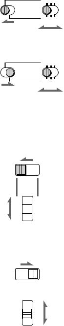
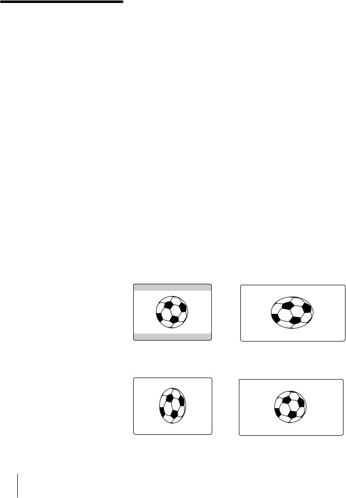
Set “WIDE PB” to “ON” on the SET UP MENU of this VCR. Black bands appear at the top and the bottom (for DSR-30P, bottom only) of the screen and the screen looks wide (CINEMA mode.)
To watch on a wide-screen TV
Set “WIDE PB” to “OFF” on the SET UP MENU of this VCR, and set the wide-screen TV to “16:9 FULL mode.”
In the case of a wide-screen TV compatible with the Video-ID on the wide screen system, it enters into the FULL mode automatically.
When “WIDE PB” is set to “ON” |
|
4:3 monitor |
Wide-screen TV |
(Illustration: DSR-30) |
|
When “WIDE PB” is set to “OFF” |
|
4:3 monitor |
Wide-screen TV |
30 EN Playback
 Loading...