


MD-MT877/MD-MT877C
SERVICE MANUAL
No. S3118MDMT877/
PORTABLE MINIDISC RECORDER
MD-MT877(S)
MODEL MD-MT877C(S)
• In the interests of user-safety the set should be restored to its original condition and only parts identical to those specified be used.
CONTENTS |
|
|
Page |
SPECIFICATIONS ................................................................................................................................................................. |
2 |
NAMES OF PARTS ............................................................................................................................................................... |
3 |
OPERATION MANUAL .......................................................................................................................................................... |
5 |
DISASSEMBLY .................................................................................................................................................................... |
10 |
REMOVING AND REINSTALLING THE MAIN PARTS ....................................................................................................... |
11 |
ADJUSTMENT ...................................................................................................................................................................... |
12 |
NOTES ON SCHEMATIC DIAGRAM .................................................................................................................................. |
28 |
TYPES OF TRANSISTOR AND DIODE .............................................................................................................................. |
28 |
BLOCK DIAGRAM ............................................................................................................................................................... |
29 |
SCHEMATIC DIAGRAM ...................................................................................................................................................... |
30 |
WIRING SIDE OF P.W.BOARD ........................................................................................................................................... |
32 |
VOLTAGE ............................................................................................................................................................................ |
36 |
WAVEFORMS OF MD CIRCUIT ......................................................................................................................................... |
37 |
TROUBLESHOOTING ......................................................................................................................................................... |
38 |
FUNCTION TABLE OF IC .................................................................................................................................................... |
41 |
PARTS GUIDE/EXPLODED VIEW |
|
PACKING OF THE SET (MD-MT877(S) FOR U.S.A. ONLY) |
|
This document has been published to be used
SHARP CORPORATION for after sales service only.
The contents are subject to change without notice.
MD-MT877/MD-MT877C
FOR A COMPLETE DESCRIPTION OF THE OPERATION OF THIS UNIT, PLEASE REFER TO
THE OPERATION MANUAL.
|
|
|
SPECIFICATIONS |
|
|
||
|
|
|
|
||||
Power source |
DC 1.2V: Rechargeable Nickel-Metal Hydride battery (AD-N55BT) x 1 |
|
|
||||
|
DC 5V: |
AC adaptor (AC 120V, 60 Hz) |
|
|
|
|
|
|
DC 1.5V: Commercially available, “AA” size (LR6), alkaline battery x 1 |
|
|
||||
|
DC 1.5V: Separately available car adaptor, AD-CA55X (for cars with a 12-24V DC negative ground electrical sys- |
||||||
|
|
tem) (Used with separately available plug adaptor (AD-M66PA)) |
|
||||
Power consumption |
7 W (AC adaptor) |
|
|
|
|
|
|
Output power |
RMS; 10 mW (5 mW + 5 mW) (0.2% T.H.D.) |
|
|
|
|
||
Charging time |
Approx. 3.5 hours |
|
|
|
|
|
|
Input sensitivity |
MIC H: reference input level |
0.25 mV |
input impedance |
10 k ohms |
|||
|
MIC L: |
reference input level |
2.5 mV |
input impedance |
10 k ohms |
||
|
LINE: |
reference input level |
100 mV |
input impedance |
20 k ohms |
||
Output level |
Earphones: maximum output level 5 mW + 5 mW |
|
load impedance |
32 ohms |
|||
|
LINE: |
specified output |
250 mV (-12 dB) |
load impedance |
10 k ohms |
||
Dimensions |
Width: |
2-27/32” (71.9 mm) |
Height: 11/16” (16.8 mm) |
Depth: 3-1/8” (78.7 mm) |
|||
Weight |
0.29 lbs. (131 g) with rechargeable battery |
|
|
|
|
||
|
|
|
|
||||
Input jack |
Line/optical digital, microphone (powered by the main unit) |
|
|
||||
Output jack |
Earphones (impedance: 32 ohms)/remote control unit |
|
|
|
|||
Type |
Portable MiniDisc recorder |
|
|
|
|
|
|
Signal readout |
Non-contact, 3-beam semiconductor laser pickup |
|
|
|
|
||
Audio channels Stereo 2 channels/monaural (long-play mode) 1 channel
Frequency response 20 – 20,000 Hz (± 3 dB)
Rotation speed Approx. 400 – 1,350 rpm
Error correction ACIRC (Advanced Cross Interleave Reed-Solomon Code)
Coding |
ATRAC/ATRAC3 (Adaptive TRansform Acoustic Coding), 24-bit computed type |
Recording method |
Magnetic modulation overwrite method |
Sampling frequency |
44.1 kHz (32 kHz and 48 kHz signals are converted to 44.1 kHz, and then recorded.) |
Wow and flutter |
Unmeasurable (less than ±0.001% W. peak) |
Battery life
|
Stereo |
2 times long |
4 times long |
|||
|
|
|
|
|
|
|
When using the rechargeable battery |
Continuous |
Continuous |
Continuous |
Continuous |
Continuous |
Continuous |
(fully charged) included with the unit |
recording: |
play: |
recording: |
play: |
recording: |
play: |
|
Approx. |
Approx. |
Approx. |
Approx. |
Approx. |
Approx. |
|
6.5 hours |
12 hours |
9 hours |
13.5 hours |
11.5 hours |
15 hours |
When using one, commercially avail- |
Continuous |
Continuous |
Continuous |
Continuous |
Continuous |
Continuous |
able, high capacity, “AA” size (LR6), al- |
recording: |
play: |
recording: |
play: |
recording: |
play: |
kaline battery (The rechargeable bat- |
Approx. |
Approx. |
Approx. |
Approx. |
Approx. |
Approx. |
tery is in the unit, discharged.) |
6 hours |
16 hours |
10 hours |
19.5 hours |
13 hours |
22 hours |
When using one, commercially avail- |
Continuous |
Continuous |
Continuous |
Continuous |
Continuous |
Continuous |
able, high capacity, “AA” size (LR6), al- |
recording: |
play: |
recording: |
play: |
recording: |
play: |
kaline battery with the rechargeable bat- |
Approx. |
Approx. |
Approx. |
Approx. |
Approx. |
Approx. |
tery (fully charged) |
15 hours |
29 hours |
22 hours |
33 hours |
30 hours |
40 hours |
|
|
|
|
|
|
|
●The above values are the standard values when the unit is operated horizontally and charged at an ambient temperature of 77°F (25°C). (The
operable duration with the rechargeable battery will be shorter when the unit is carried around.)
●The volume level is set at “VOL 15”.
●The LED is set at “LIGHT OFF”.
●Operable duration with a commercially available battery varies depending on its maker, type, and conditions of use.
●“Fully charged” means that the charging is complete after approximately 3.5 hours since the remaining amount of the battery is reduced to “ ” (1 bar).
Specifications for this model are subject to change without prior notice
– 2 –
MD-MT877/MD-MT877C
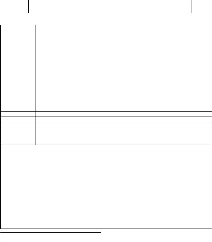
NAMES OF PARTS
Main unit
1.Record/Track Mark Button
2.Mode Button
3.Volume/Cursor/Fast Forward/Fast Reverse/ Recording Level/Name Select Button
4.Stop/Power Off/Hold Button
5.Open Lever
6.Display/Character Select Button
7.Edit/Auto Mark/Time Mark Button
8.Play/Pause Button
9.Enter/Fast Play/Synchro Button
10.Bass/Delete Button
11.Rechargeable Battery Cover
12.Handstrap Holder
13.Optical/Line Input Jack
14.Microphone Input Jack
15.Remote Control/Earphones/Line Output Jack
3 |
4 |
8 |
9 |
||
2 |
|
|
1 |
|
10 |
5
6
7
11
15
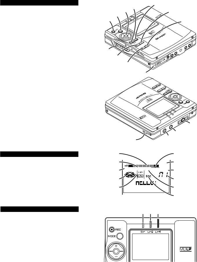
Main unit display panel
1.Level Meter
2.Record Indicator
3.Synchro Recording Indicator
4.Operation Indicator
5.Long-play/Recording Mode Indicator
6.Character/Time Information Indicator
7.Repeat Indicator
8.Battery Indicator
9.Random Indicator
10.Track Number Indicator
11.TOC Indicator
12.Disc Name Indicator
3-color LED
Various modes are indicated with three colors of lights.
Charging |
Lighting starting with yellow-green light. |
Refresh |
Extinguishing starting with orange light |
|
after all the lights are lit. |
Playback |
Flashing the color of the activated play- |
|
back mode. |
Recording |
Flashing the color of the activated re- |
|
cording mode. |
Fast Forward |
Flashing starting with yellow-green light. |
Fast Reverse |
Flashing starting with orange light. |
Volume (+) |
Lighting starting with yellow-green light. |
Volume (–) |
Extinguishing instantly starting with or- |
|
ange light after all the lights are lit. |
TOC |
Reading: flashing at random. |
|
|
|
|
14 |
|
12 |
13 |
|
|
|
1 |
|
7 |
2  8
8
3


 9
9
4 10
10
5


 11
11
6 12
12
Yellow-
green Blue Orange
– 3 –
MD-MT877/MD-MT877C
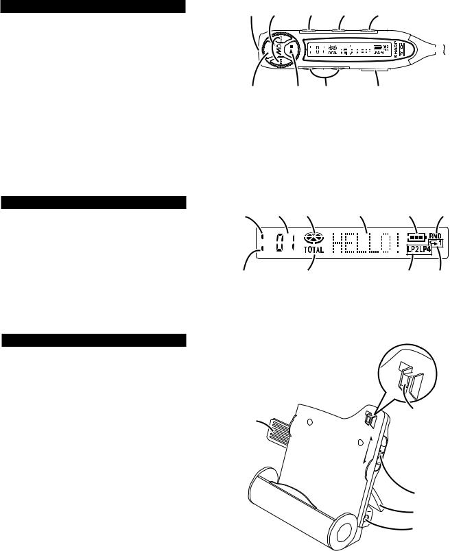
Remote control unit
1.Earphones Jack
2.Fast Forward/Fast Reverse Button
3.Display Button
4.Play Mode Button
5.Sound/Track Mark Button
6.Stop/Power Off Button
7.Play/Pause Button
8.Volume Button
9.Hold Switch
Remote control display panel
1.Record Indicator
2.Track Number Indicator
3.Operation Indicator
4.Character/Time Information Indicator
5.Battery Indicator
6.Random Indicator
7.Synchro Recording Indicator
8.Total Track Number Indicator
9.Long-play/Recording Mode Indicator
10.Repeat Indicator
Battery charger
1.Remote Control Holder
(You can hang the remote control on it.)
2.Lock Detector
3.Hook For Fixing The Main Unit
4.Charge/Operation Switch
5.Stand
6.AC Adaptor Connecting Jack
1 |
2 |
|
3 |
4 |
5 |
|
|
|||
|
|
|
|
|
|
|
|
|
|
|
|
|
|
|
|
|
|
|
|
|
|
|
|
|
|
|
|
|
|
|
|
|
|
|
|
|
|
|
|
|
|
|
|
|
|
|
|
|
|
|
|
|
|
|
|
|
|
|
|
|
|
|
|
|
|
|
|
|
|
|
|
|
|
|
|
|
|
|
|
|
|
|
|
|
|
|
|
|
|
|
|
|
|
|
|
|
|
|
6 |
7 |
8 |
9 |
1 |
2 |
3 |
4 |
5 |
6 |
7 |
8 |
9 |
10 |
2
1 |
3 |
|
CHARGE |
||
|
||
|
OPERATION |
4
5
6
– 4 –
MD-MT877/MD-MT877C
OPERATION MANUAL
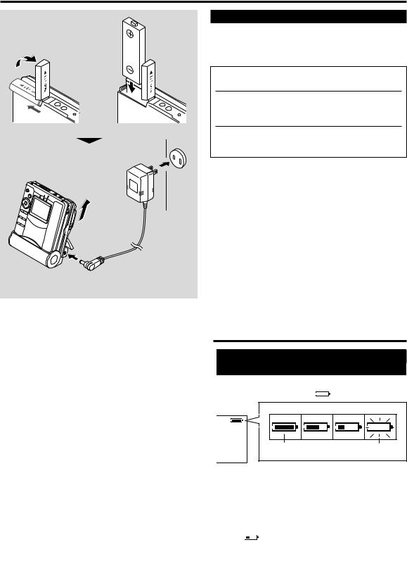
Using with the Rechargeable Battery
Do not force the battery cover open too far.
AC 120V 60Hz
Charge mode
Charging
When the rechargeable battery is used for the first time or when you want to use it after a long period of disuse, be sure to charge it fully.
1 Insert the rechargeable battery.
2 Move the Charge/Operation switch to charge mode.
3 Place the portable MD into the battery charger and connect the AC adaptor.
●After the rechargeable battery is charged or used, it will get slightly warm. This is normal.
●When the portable MD is turned on or operating, the battery will not be charged.
To the DC IN 5V jack
Checking Displays
Checking the remaining amount of battery level
The remaining amount of battery level is shown by the battery indicator ( 

 ) during operation.
How to read the battery indicator |
|
When the battery |
When the battery |
level is high |
low is very low |
●When the battery is completely discharged, the battery indicator will flash. Recharge the battery or replace the alkaline battery with a new one.
●When the battery has run completely out, “BATT EMPTY (LoBATT)” will appear. Then, the power will be disconnected automatically.
Notes:
●If you use the battery which you stopped charging halfway, “
 ” may appear. It does not mean that the battery is completely charged.
●The battery indicator will not correctly display the remaining capacity for approximately 20 seconds after the power has been turned on.
●When the AC adaptor or a separately available car adaptor is used, the battery indicator will not be shown.
●The number of bars shown in the battery indicator may increase or decrease, depending on the operation being performed. This is normal.
– 5 –

MD-MT877/MD-MT877C
Error Messages
ERROR MESSAGES |
|
MEANING |
|
REMEDY |
|
BATT EMPTY |
● The battery is run down. |
● Charge the rechargeable battery or replace the alka- |
|||
(LoBATT) |
|
|
line battery (or use the AC adaptor for power). |
|
|
BLANK MD |
● Nothing is recorded. |
● Replace the disc with a recorded disc. |
|||
(BLANK) |
|
|
|
|
|
Can’t COPY |
● You tried to record from a copy prohibited |
● Record using the analog cable. (MD-MT877(S)) |
|||
(Can’tC) |
MiniDisc. |
● Record using the analogue cable. (MD-MT877C(S)) |
|
||
Can’t EDIT |
● A track cannot be edited. |
● Change the stop position of the track and then edit it. |
|||
(Can’tE) |
|
|
|
|
|
Can’t READ * |
● The disc data cannot be read because the disc |
● Reload the disc. |
|||
(Can’tS) |
is damaged. |
● Replace it with another recorded disc. |
|||
(Can’tT) |
|
|
|
|
|
(Can’tU) |
|
|
|
|
|
Can’t REC |
● Recording cannot be performed correctly due to |
● Re-record or replace it with another recordable disc. |
|||
(Can’tR) |
vibration or shock. |
|
|
||
Can’t STAMP |
● Stamp function does not work. |
● Check the number of tracks. |
|
||
Can’t WRITE |
● Cannot save the TOC information correctly to a |
● Replace the disc with another recordable disc. |
|||
(Can’tW) |
MiniDisc. (A large portion of the disc has been |
|
|
||
|
|
damaged.) |
|
|
|
CHARGEmode |
● The Charge/Operation switch is not set to the |
● Set the Charge/Operation switch to the operation mode. |
|||
|
|
operation mode when using this unit with the AC |
|
|
|
|
|
adaptor. |
|
|
|
DEFECT |
● The disc is scratched. |
● If the sound you hear is not right, record again. |
|||
(DEFECT) |
|
|
● Replace the disc with another recordable disc. |
|
|
DISC FULL |
● The disc is out of recording space. |
● Replace it with another recordable disc. |
|||
Er-MD ** |
● The microprocessor has reported a system fault |
● To have it repaired, go to the distributor where you pur- |
|
||
(ErMD*) |
and the unit is out of order. |
chased the unit. |
|
||
HOLD |
● The unit is in the hold mode. |
● Return the HOLD switch to its original position. |
|||
(HOLD) |
|
|
|
|
|
LOCKED |
● You removed a MiniDisc while recording or |
● Turn off the power and remove the MiniDisc. |
|||
(Can’tLOCK) |
editing. |
|
|
||
|
|
|
|
|
|
ERROR MESSAGES |
|
MEANING |
|
REMEDY |
NO DISC |
● A disc has not been loaded. |
● Load a disc. |
||
NO SIGNAL |
● Poor connection of the digital cable. |
● Connect the digital cable securely. |
||
(noSIG.) |
● No output signal comes out from the connected |
● If the portable CD player has a function to prevent sound |
||
|
|
unit to playback. |
skips, deactivate it. |
|
|
|
● The input signal has improper sampling fre- |
● Playback with the connected unit. |
|
|
|
quency. |
|
|
PLAY MD |
● You recorded on a playback-only disc. |
● Replace it with a recordable disc. |
||
(PLAYmd) |
|
|
|
|
POWER ? ● The battery charger is defective.
●To have it repaired, go to the distributor where you purchased the unit.
PROTECTED ● The write protection tab of a MiniDisc is set to the protected position.
● You tried to record on a playback-only disc.
●Move the write protection tab back to its original position.
●Replace it with a recordable MiniDisc.
SORRY |
● Since a track number is currently being located |
● Wait for a while and try the operation again. |
(Sorry) |
or updated, the unit cannot accept your com- |
|
|
mand. |
|
TEMP OVER |
● The temperature is too high. |
● Turn off the power, and wait for a while. |
(TEMP!) |
|
|
TOC FORM ** |
● There is an error in the recording signal. |
● Erase all of the tracks, and then record again. |
(Tform**) |
|
|
TOC FULL |
● There is no space left for recording character |
● Replace it with another recordable disc. |
|
information (track names, disc names, etc.). |
|
Tr. Protect |
● The track has been protected from being erased. |
● Edit the track with the device on which it was recorded. |
? DISC |
● A disc which contains data other than music was |
|
(? DISC) |
played. |
● A disc which contains non-music data cannot be played. |
|
● There is an error in the signal recorded on the |
● Replace it with another recorded disc. |
|
disc. |
|
|
● Stamping is not possible. |
● Retry. |
( ) : Error messages seen on the remote control. Number or symbol appears in * position.
– 6 –

MD-MT877/MD-MT877C
MiniDisc System Limitations
The unit may have the following symptoms while recording or editing. The unit is not out of order.
SYMPTOM |
|
LIMITATIONS |
|
|
|
“DISC FULL” or “TOC FULL” appears even though the MiniDisc still has recording time left.
More than 255 tracks (maximum) cannot be recorded regardless of the recording time.
If the MiniDisc is recorded or edited repeatedly or if it has scratches (recording skips scratched parts), you may not be able to record the maximum tracks above.
The remaining recording time does not increase even though you erased tracks.
The unit does not count non-recorded portions that last 12 or fewer seconds to display the remaining recording time. The time may not increase even if you erase short tracks.
The total of the recorded time and the remaining time does not match the maximum recordable time.
One cluster (approximately 2 seconds) is the minimum unit for recording. For example, a 3-second track uses 2 clusters (approximately 4 seconds). Therefore, the actual recordable time may be shorter than the displayed time.
Combine function does not work.
A MiniDisc on which recording and editing are repeated may not allow the combine function.
Sound skips in fast reverse/forward.
One track is divided and recorded in separate places on a repeatedly recorded or edited MiniDisc.
Sound may skip.
A track number is created in the middle A track number may be created if there are scratches or dust on the MiniDisc. of a track.
Troubleshooting
Many potential “problems” can be resolved by the owner without calling a service technician.
If something seems to be wrong with this product, check the following before calling your authorized SHARP dealer or service center.
PROBLEM |
|
|
CAUSE |
|
|
|
|
The unit does not ● |
Is the AC adaptor disconnected? |
||
turn on. |
|
● |
Is the battery exhausted? |
|
|
● |
Is the unit in the hold mode? |
|
|
● Has condensation formed inside the |
|
|
|
|
unit? |
|
|
● Is the unit being influenced by me- |
|
|
|
|
chanical shock or by static electric- |
|
|
|
ity? |
|
|
||
No sound |
is ● Is the volume set too low? |
||
heard from the ● |
Is the remote control unit or the ear- |
earphones. |
phones plugged in? |
● Are you trying to play a MiniDisc with |
|
|
data on it instead of a MiniDisc contain- |
|
ing music? |
When the opera- ● |
Is the unit in the hold mode? |
|
tion buttons are ● |
Is the battery exhausted? |
|
pressed, the unit ● |
Is the remote control unit plug or the |
|
does not respond. |
|
earphones plug inserted firmly? |
|
|
|
Some sounds ● |
Is the battery exhausted? |
|
are skipped. |
● Is the unit being subjected to exces- |
|
|
|
sive vibration? |
PROBLEM |
|
CAUSE |
|
|
|
The MiniDisc can- ● Has the track number or character not be ejected. information been updated on the
disc yet?
●Is the unit in the recording or editing mode?
Recording and ● Is the MiniDisc protected against editing are im- accidental erasure?
possible. ● Is the unit connected properly to the other equipment?
●Is the AC adaptor unplugged or did a power failure occur while recording or editing?
●Is the unit in the hold mode?
●Is an optical signal being output from the stereo system?
Read the operation manual for the stereo system.
The battery cannot ● Is the select switch for charging/ be charged. operation set on the charging side?
● Is the jack clean?
Nothing appears ● Is the remote control display set to on the remote “LIGHT OFF”?
control display.
– 7 –
MD-MT877/MD-MT877C
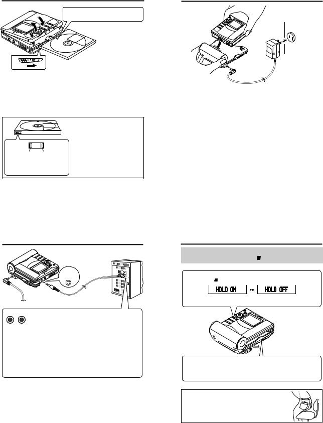
1 Insert a MiniDisc
Inserte un minidisco
|
4 |
Insert according to the direction of the arrow. |
|||
2 |
Insértelo de acuerdo con la dirección de la flecha. |
||||
|
|||||
|
|
|
|
||
|
3 |
|
|
|
|
1 |
|
|
|
|
|
1 Slide the OPEN lever to re- |
3 Insert a MiniDisc as shown. |
||||
lease the compartment door. |
Inserte un minidisco como se |
||||
Deslice la palanca OPEN para |
|||||
muestra. |
|
||||
abrir la puerta del comparti- |
4 Close the compartment. |
||||
miento. |
|
|
|||
2 Lift it up. |
|
|
Cierre el compartimiento. |
||
|
|
|
|
||
Levantelo. |
|
|
|
|
|
|
|
|
When you record on a MiniDisc, |
||
|
|
|
check that the erase prevention tab |
||
|
|
|
is set to the “recordable” position. |
||
|
|
|
Cuando desee grabar en un |
||
|
|
|
minidisco, compruebe |
que la |
|
|
|
|
lengüeta de protección |
contra |
|
Recordable |
Recording |
|
borrado esté colocada en la posición |
||
|
para "poder grabar". |
|
|||
Para poder |
prevented |
|
|
||
|
|
|
|||
Para no poder |
|
|
|
||
grabar |
|
|
|
||
|
grabar |
|
|
|
|
2 Connect the AC adaptor
Conecte el adaptador de CA
 RELEASE
LOCK
To the DC IN 5V jack
A la toma DC IN 5V
Insert securely, all the way in.
Insértelo con seguridad a fondo.
AC 120V, 60 Hz
120V CA, 60Hz
To an AC outlet
A un tomacorriente de CA
1 Move the Charge/Operation |
3 Move the Charge/Operation |
switch to Charge mode (RE- |
switch to Operation mode |
LEASE). |
(LOCK). |
Mueva el selector de carga/ |
Mueva el selector de carga/ |
operación al modo de carga |
operación al modo de operación |
(RELEASE). |
(LOCK). |
2 Insert the portable MD into |
4 Plug the AC adaptor. |
the battery charger. |
Enchufe el adaptador de CA. |
Inserte el MD portátil en el |
|
cargador de baterías. |
|
Before using the unit with a rechargeable battery, the battery has to be charged. Refer to “Using with the rechargeable battery”.
Antes de emplear el aparato con una batería recargable, se deberá cargar la batería. Consulte el apartado de "Empleo con la batería recargable".
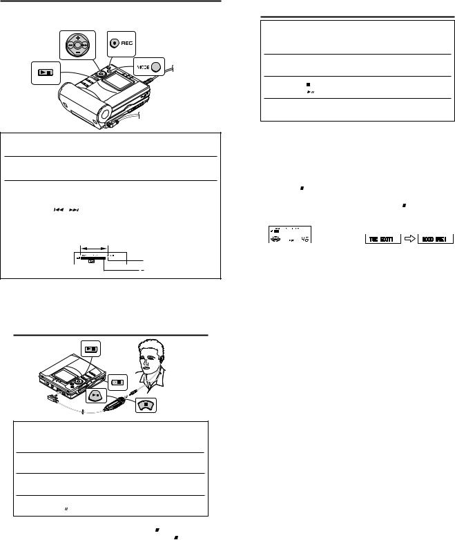
3 Connection
Conexión
Red: To Right
Rojo: A la
derecha
OPTICAL/
LINE IN
White: To Left
Blanco: A la izquierda
LINE OUT To a stereo system with “LINE OUT” or “AUDIO OUT”
jacks (See left. Analog connection)
RIGHT LEFT Note:
If the audio system has only one pair of jack then they are usually input only and recording via this connection is not possible.
A un sistema estéreo provisto de tomas de salida de línea "LINE OUT" o de salida de audio "AUDIO OUT" (Vea a la izquierda, Conexión analógica)
Nota:
Si el sistema de audio sólo tiene un par de tomas, normalmente son sólo de entrada y no puede realizarse la grabación mediante esta conexión.
Preparation for use
Preparación para su utilización
The unit does not work if the •  / –HOLD button is set to HOLD.
Este aparato no funciona si el botón • / –HOLD está puesto en HOLD.
Press the • 
 / –HOLD button for 2 seconds or more.
Pulse el botón • /– HOLD durante 2 o más segundos.
Hold |
Released |
Retención |
Liberación |
 Operation mode
Modo de operación
For operations
Para operaciones
Move it to operation mode when playing back or recording.
Muévalo a la posición del modo de operación para la reproducción o grabación.
CAUTION:
It is not recommendable to put the MiniDisc into a rear pocket, as this may damage the product when sitting.
PRECAUCIÓN:
No se recomienda ponerse un minidisco en el bolsillo trasero del pantalón, porque podría dañarlo al sentarse.
– 8 –
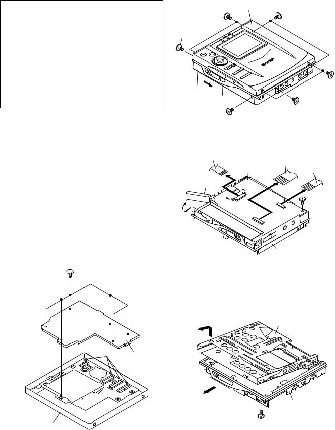
Recording
Grabación
Check that the unit is connected to the stereo system.
Compruebe que el aparato esté conectado al sistema estéreo.
1 Press the REC button.
Pulse el botón REC.
2 Begin playback on the stereo system connected to this unit.
Inicie la reproducción en el sistema estéreo conectado a este aparato.
3 Press the or
or button to adjust the recording level.
Adjust the recording level so that the maximum sound volume from the source makes the reading swing somewhere between –4 dB and 0 dB.
Pulse el botón |
o |
para ajustar el nivel de grabación. |
Ajuste el nivel de grabación para que el volumen de sonido máximo de la fuente produzca una indicación de entre –4 dB y 0 dB.
Level meter indicator
Indicador del medidor de nivel
0dB
4dB
Playing
Reproducción
MD-MT877/MD-MT877C
4 Press the PAUSE button on the stereo system to enter the playback pause mode at the point you wish to start recording.
Pulse el botón PAUSE del sistema estéreo para entrar en el modo de pausa de reproducción en el punto en el que desee iniciar la grabación.
5 Press the MODE button repeatedly to select the recording mode.
Pulse repetidamente el botón MODE para seleccionar el modo de grabación.
6 Press the button to start recording.
Pulse el botón |
para iniciar la grabación. |
7 Begin playback on the stereo system, the output will be recorded.
Inicie la reproducción del sistema estéreo, y se grabará la salida.
To stop recording
Press the •  / :OFF button.
When recording stops, “TOC” appears (Table Of Contents). While “TOC” appears, the MiniDisc recorded contents have not yet been updated.
Para detener la grabación
Pulse el botón • /:OFF.
Cuando se detenga la grabación, aparecerá “TOC” (índice). Mientras aparece “TOC”, aún no se habrá actualizado el contenido grabado en el MD.


 TOC display
Visualización TOC
To update the recorded contents of the MiniDisc
Press the •  / :OFF button while in the stop mode.
The power turns off after recorded contents have been updated on the MiniDisc.
Para actualizar el contenido grabado del MD
Pulse el botón • /:OFF en el modo de parada.
La alimentación se desconectará después de haber actualizado el contenido grabado en el MD.
1 Insert the earphones plug firmly into the earphones jack on the remote control unit.
Inserte firmemente la clavija de los auriculares en la toma de auriculares del controlador remoto.
2 Plug the remote control into the  jack on the unit.
Enchufe el controlador remoto a la toma 
 del aparato.
3 Insert a MiniDisc.
Inserte un MD
4 Press the  button.
Pulse el botón  .
.
To stop playback
Press the •  / :OFF button (Remote control: press the
  button).
If the unit is not operated for at least 2 minutes while in the stop mode, the power will shut off automatically.
Para detener la reproducción
Pulse el botón • /:OFF. (Controlador remoto: pulse el botón .)
Si el aparato no se utiliza durante un mínimo de 2 minutos en el modo de parada, la alimentación se desconectará automáticamente.
– 9 –
MD-MT877/MD-MT877C
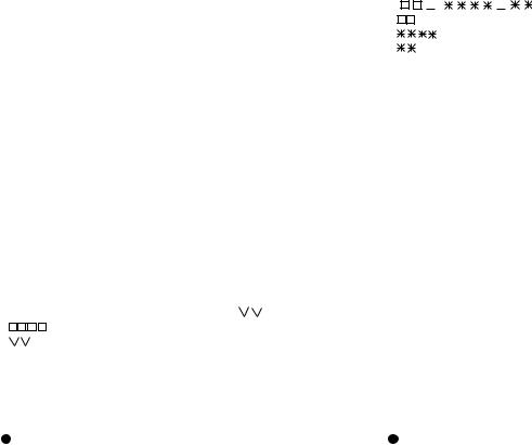
DISASSEMBLY
Cares before disassembling
When assembling the machine after disassembling or repair, observe the following requirements so as to ensure safety and performance.
1.Remove the batteries from the machine, and take out the mini-disc.
2.When assembling after repair, be sure to position the wires in the same location.
Use the specified screws to fix the cabinet and the mechanism unit. The use of the screws with length other than specified may cause contact with the mechanism unit resulting in malfunction.
3.When repairing, pay close attention so not to damage the IC from static electricity.
STEP |
REMOVAL |
|
PROCEDURE |
|
FIGURE |
|
|
|
|
|
|
1 |
Bottom Cabinet |
1. Screw ..................... |
(A1) x5 |
10-1 |
|
|
|
|
|
|
|
2 |
Top Cabinet |
1. |
Open the Top cabinet. |
10-1 |
|
|
|
2. Screw ..................... |
(B1) x4 |
|
|
|
|
3. |
Flexible PWB .......... |
(B2) x1 |
10-2 |
|
|
|
|
|
|
3 |
Main PWB |
1. |
Open the rechargeable |
10-2 |
|
|
|
|
battery compartment of the |
|
|
|
|
|
direction indicated by arrows. |
|
|
|
|
2. |
Screw .................... |
(C1) x1 |
|
|
|
3. |
Flexible PWB ......... |
(C2) x2 |
|
|
|
|
|
|
|
4 |
MD Mechanism |
1. |
Pull the main frame to the A |
10-3 |
|
|
|
|
direction and remove the MD |
|
|
|
|
|
mechanism upward. |
|
|
|
|
2. |
Screw .................... |
(D1) x1 |
|
|
|
|
|
|
|
5 |
LCD PWB |
1. |
Screw ...................... |
(E1) x6 |
10-4 |
|
|
2. Hook ....................... |
(E2) x4 |
|
|
|
|
|
|
|
|
 (E1) x 6
ø 1.4 x 2 mm
(E2) x 4 |
LCD PWB |
|
Top Cabinet
Figure 10-4
(B1) x 2
ø 1.4 x 2 mm Top Cabinet
(A1) x 2
ø 1.4 x 2 mm
(A1) x 1
ø 1.4 x 2 mm
OPEN |
Bottom Cabinet
EJECT
Knob
(A1) x 1
ø 1.4 x 2 mm
(B1) x 2
ø 1.4 x 2 mm
 OPEN
OPEN
(A1) x 1
ø 1.4 x 2 mm
Figure 10-1
(C2) x 1(1*)
|
|
|
(B2) x 1 |
|
|
Main PWB |
(C2) x 1 |
|
Battery |
|
|
|
Cover |
pull |
|
|
|
|
|
|
|
pull |
(C1) x 1 |
2 |
|
ø 1.4 x 2.5 mm |
|
|
1 |
|
|
|
|
OPEN |
|
Main Frame
Caution:
Carefully handle the main PWB and flexible PWB. After removing the flexible PWB (1*) for the optical pickup from the connector, do not touch directly the front end of flexible PWB with your hand so as to prevent damage of optical pickup by static electricity.
Figure 10-2
MD Mechanism
OPEN
A
Main Frame
(D1) x 1
ø 1.4 x 1.5 mm
Figure 10-3
– 10 –
MD-MT877/MD-MT877C
REMOVING AND REINSTALLING THE MAIN PARTS
Remove the mechanism according to the disassembling methods 1 to 4. (See Page 10.)
How to remove the spindle motor (See Fig. 11-1.)
1.Remove the solder joints (A1) x 4 of flexible PWB.
2.Remove the screws (A2) x 3 pcs., and remove the spindle motor.
How to remove the lift motor (See Fig. 11-2.)
1.Remove the solder joints (B1) x 2 of lift motor lead wire.
2.Remove the screw (B2) x 1 pc., and remove the lift motor.
Note:
Take care so that the motor gear is not damaged. (If the gear is damaged, noise is caused.)
How to remove the sled motor (See Fig. 11-3.)
1.Remove the stop washer (C1) x 1 pc., and remove the drive gear (C2) x 1 pc.
2.Remove the screws (C3) x 2 pcs.
3.Remove the solder joints (C4) x 3 of flexible PWB., and
remove the sled motor.
Note:
Take care so that the motor gear is not damaged. (If the gear is damaged, noise is caused.)
How to remove the magnetic head (See Fig. 11-4.)
1. Remove the screws (D1) x 2 pcs. of the magnetic head and the optical pickup, and remove the solder joints (D2) x 2 pcs. of the head flexible plate.
Note:
Mount carefully so as not to damage the magnetic head.
How to reinstall the optical pickup (See Fig. 11-4.)
1.Remove the screw (E1) x 1 pc., and remove the grip spring.
2.Remove the screw (E2) x 1 pc. to remove the thrust spring, and remove the drive screw and the optical pickup from MD mechanism.
Then, remove the drive screw from the optical pickup.
(E1) x 1 |
|
|
ø 1.4 x 1.8 mm |
|
|
Grip Spring |
(D1) x 2 |
|
Drive |
|
|
ø1.4 x 1.8 mm |
|
|
Screw |
|
|
|
|
|
|
(D2)x2 |
(E2) x 1 |
|
Solder Joints |
|
|
ø 1.7 x 3.5 mm |
|
Optical Pickup |
|
|
Magnetic |
|
Thrust |
head |
|
|
|
|
Spring |
 MD Mechanism
Figure 11-4
(A2) x 3
ø 1.4 x 3 mm
Spindle Motor
Solder joints (A1) x 4
MD Mechanism
Figure 11-1
(B2) x 1
ø 1.4 x 3.8 mm
Lift Motor
Solder Joints (B1) x 2
MD Mechanism
Figure 11-2
(C3) x 2  ø 1.4 x 1.2 mm
Sled
Motor
(C1) x 1 (C2) x 1
(C4) x 3
Solder Joints
MD Mechanism
Figure 11-3
– 11 –

MD-MT877/MD-MT877C
Test disc |
ADJUSTMENT |
|
MD adjustment needs two types of disc, namely recording disc (low reflection disc) and playback-only disc (high reflection disc).
|
Type |
Test disc |
Parts No. |
|
|
|
|
|
|
1 |
High reflection disc |
MMD-110 |
88GMMD-110 |
|
|
|
(TEAC Test MD) |
|
|
2 |
Low reflection disc |
MMD-213A |
88GMMD-213A |
|
(TEAC Test MD) |
||||
3 |
Low reflection disc |
Recording |
UDSKM0001AFZZ |
|
minidisc disc |
||||
|
|
|
Note: Use the low reflection disc on which music has been recorded.
 Entering the TEST mode
1.Setting at port (in standby state, disc-free state or power nonconnected state)
(1)Set the port as follows. TEST1 : "Low"
TEST0 : "High"
(2)Press the PLAY button in the standby state (it is allowed to close the disc lid or to connect the power supply).
(3)Test Mode STOP [ T E S T _ ]
2.Setting by special button operation (in standby state)
Test mode: Perform it with the remote control.
(1)Press and hold the "PLAY MODE" button on the remote control and press the "PLAY" button.
(2)Release only the "PLAY MODE" button.
(3)Press and hold only the "PLAY" button and press the "VOL- UME–" button.
(4)Normal mode setting initialization (BASS setting, VOLUME setting, etc.)
(5)Test Mode STOP [ T E S T _ ]
(6)Press "VOLUME+" to check the microcomputer version.
(7)Press "VOLUME–" to light up all the LCDs.
 Leaving the TEST mode
(1)Press the STOP button in the TEST mode stop state or version indicating state or whole LCD lighting state.
(2)EEPROM rewrite-enable area updating.
(3)Change to standby state
 Shipping setting method
(1)Insert the rechargeable battery. Do not close the compartment.
(2)Close the battery lid twice in succession while pressing the VOLUME– button and the PLAY button on the main unit at the same time. (Turn on and off the power twice)
(3)Make sure the display changes from [INIT] to [BYE OK].
 Test Mode
1. AUTO 1 Mode |
• Perform preliminary automatic adjustment. |
|
• If the combination of mechanism and pickup |
|
PWB has been changed, be sure to start from |
|
AUTO1. |
|
|
2. AUTO 2 Mode |
• Perform ATT (attenuator) automatic adjustment. |
|
• Perform continuous playback (error rate display, |
|
jump test) |
3. TEST-PLAY Mode |
• Continuous playback from the specified address |
|
is performed. |
|
• 1 line, 10 lines or 100 steps manual jump is |
|
performed. |
|
• C1 error rate display (pit section), ADIP error |
|
rate display (groove section) |
|
• The temperature correction is performed only when |
|
servo start is performed, but the posture correction |
|
is not performed during continuous playback. |
4. TEST-REC Mode |
• Continuous record from the specified address |
|
is performed. |
|
• Change of record laser output (servo gain is |
|
also changed according to laser output). |
|
• The temperature correction is performed only |
|
when servo start is performed, but the posture |
|
correction is not performed during continuous |
|
recording. |
5. MANUAL 1 Mode |
• Temperature is displayed. |
|
• Seeing the displayed adjustment value, perform |
|
preliminary manual adjustment. |
|
(Error rate indication, jump test) |
|
|
6. MANUAL 2 Mode |
• Temperature is displayed. |
|
• Seeing the displayed adjustment value, perform |
|
ATT (attenuator) manual adjustment. |
|
• Continuous playback is performed |
|
(error rate display, jump test). |
7. ERROR INFORMATION |
• Error information is displayed. |
Mode |
• Error information is initialized |
8. NORMAL Mode |
• The mode is changed from the TEST mode to |
|
the normal mode without adjustment. |
|
• In the normal mode the internal operation mode, |
|
memory capacity, etc. areindicated. |
|
• In the normal mode both temperature correction |
|
and posture correction are performed. |
9. EEPROM Mode |
• Factors of digital servo are changed manually. |
|
• Cut-off frequency of BASS1, BASS2 and BASS3 |
|
is selected manually. |
|
• Temperature detection terminal voltage is |
|
measured, and the reference value is set. |
|
• Defaults are selected and set. |
|
• Setting of EEPROM protect area is updated. |
|
|
– 12 –

 Operation in each TEST mode
1. AUTO1 Mode
•When the STOP button is pressed while the AUTO1 menu appears or during automatic adjustment, the mode changes to the TEST mode stop state. At this time the adjustment value is not output.
•Be sure to adjust, using the specified disc MMD-213A.
•Adjustment NG; Adjustment item out of range, focus ON failure, and adjustment error
•When the PLAY button is pressed while ADJ. OK is displayed, AUTO2 is executed.
2. AUTO2 Mode
•When the STOP button is pressed while the AUTO2 menu appears or during automatic adjustment, the mode changes to the TEST mode stop state. At this time the adjustment value is not output.
•Adjustment NG; Adjustment item out of range, and adjustment error.
•When the PLAY button is pressed while ADJ. OK is displayed, TEST _PLAY is executed.
3. MANUAL1 Mode
•Adjustment item to be made in AUTO1 mode is performed manually.
•When the VOLUME+ button is pressed during adjustment, the setting increases, and the new setting is output.
•When the VOLUME– button is pressed during adjustment, the setting decreases and the new setting is output.
•If the VOLUME+/– button is held down, the setting changes continuously with 100 ms cycle.
*In this operation, the setting change is performed for each digit. The digit is changed by pressing the MODE button.
•If the setting is within the allowable range, the RANDOM display lights.
•When the STOP button is pressed during MANUAL1 menu or measurement or adjustment, the state is changed to the TEST mode stop state.
4. MANUAL2 Mode
•Adjustment item to be made in AUTO2 mode is performed manually.
•When the VOLUME+ button is pressed during adjustment, the setting increases, and the new setting is output.
•When the VOLUME– button is pressed during adjustment, the setting decreases and the new setting is output.
•If the VOLUME+/– button is held down, the setting changes continu-
ously with 100 ms cycle.
*In this operation, the setting change is performed for each digit. The digit is changed by pressing the MODE button.
•If the setting is within the allowable range, the RANDOM display lights.
•When the STOP button is pressed during MANUAL2 menu or measurement or adjustment, the state is changed to the TEST mode stop state.
•When the PLAY button is pressed in B-ATT set state, the mode is changed to the continuous playback mode.
•As for operation during continuous playback refer to "TEST-PLAY mode explanation".
MD-MT877/MD-MT877C
5. TEST-PLAY Mode
•When the STOP button is pressed while the TEST-PLAY menu appears, or in TEST-PLAY or continuous playback mode, the mode changes to the TEST mode stop state.
•When the PLAY button is pressed while the TEST-PLAY menu appears, continuous playback is initiated from the current pickup position.
•Whenever the DISP button is pressed in the TEST-PLAY menu, the target address changes as follows.
0032 — 03C0 — 0700 — 08A0 — 0950— 0032 — When the PLAY button is pressed while a target address is displayed, continuous playback is performed after searching that address.
•Each time the MODE button is pressed while the TEST-PLAY mode target address is displayed, the digit which is changed by pressing the FAST FORWARD/REVERSE button is changed as follows.
0032 — 0032 — 0032 — 0032 —
•When the FAST FORWARD button is pressed in the TEST-PLAY mode target address is displayed, the digit of address specified by the MODE button is set to +1h. (0 to F)
•When the FAST REVERSE button is pressed in the TEST-PLAY mode target address is displayed, the digit of address specified by the MODE button is set to -1h. (0 to F)
*When the FAST FORWARD/REVERSE button is held down, the setting changes continuously, one cycle being 100 ms.
•When the BASS button is pressed in the continuous playback mode, the number of jump lines changes as follows.
1— 10 — 100 step — 1
*After the number of jump lines is indicated for one second, the address indication is restored. [ 

 T R ] or [ 100 stp ]
•When the FAST FORWARD button is pressed in the continuous playback mode, the specified number of lines is jumped in the FWD direction.
•When the FAST REVERSE button is pressed in the continuous playback mode, the specified number of lines is jumped in the REV direction.
*When the FAST FORWARD/REVERSE button is held down, jump is repeated every approx. 100 ms.
•Whenever the DISP button is pressed in the continuous playback mode, the indication changes as follows.
* Pre-mastered disc |
|
|
|
|
|
Continuous playback |
[ |
S |
Q |
] |
|
(SUBQ address indication) |
|
|
|
|
|
| |
|
|
|
|
|
Continuous playback |
[ |
C |
E |
] |
|
(C1 error indication) |
|
|
|
|
|
| |
|
|
|
|
|
Continuous playback |
[ |
S |
Q |
] |
|
(SUBQ address indication) |
|
|
|
|
|
* Recordabl disk |
|
|
|
|
|
Continuous playback |
[ |
A |
P |
|
] |
|
|||||
(ADIP address indication) |
|
|
|
|
|
| |
|
|
|
|
|
Continuous playback |
[ |
C |
E |
] |
|
(C1 error indication) |
|
|
|
|
|
| |
|
|
|
|
|
Continuous playback |
[ |
A |
E |
] |
|
(ADIP error indication) |
|
|
|
|
|
| |
|
|
|
|
|
Continuous playback |
[ |
A |
P |
] |
|
(ADIP address indication) |
|
|
|
|
|
– 13 –
MD-MT877/MD-MT877C
6.TEST-REC Mode
•When the STOP button is pressed while the TEST-REC menu appears, or in the TEST-REC mode or continuous record mode, the mode changes to the TEST mode stop state.
•Whenever the DISP button is pressed in the TEST-REC menu, the target address changes as follows.
0032 — 03C0 — 0700 — 08A0 —0950 — 0032 —
When the PLAY button is pressed while a target address is displayed, continuous playback is performed after searching that address.
•Whenever the MODE button is pressed in the TEST-REC mode target address is displayed, the digit which is changed by the FAST FORWARD/REVERSE button changes as follows.
0032 — 0032 — 0032 — 0032 —
•When the FAST FORWARD button is pressed in the TEST-REC mode target address is displayed, the digit of address specified by the MODE button is set to +1h.(0 to F)
•When the FAST REVERSE button is pressed in the TEST-REC mode target address is displayed, the digit of address specified by the MODE button is set to -1h. (0 to F)
*When the FAST FORWARD/REVERSE button is held down, the setting changes continuously, one cycle being 100 ms.
•When the VOLUME+/– button is pressed in the TEST-REC mode or continuous record mode, the laser record power changes.
(Servo gain changes also according to record power.)
*After the laser record power is indicated for one second, the ad-
|
dress indication is restored. [ R P W _ |
|
|
|
] |
||||
• |
|
|
|
|
: Address |
|
|
|
|
• |
|
|
|
|
: Laser power cord |
|
|
|
|
|
|
|
|
|
|
|
|
||
•Operation is disabled if the premastered disc or disc is in miseraseprotected state.
7. NORMAL Mode
•When the STOP button is pressed while the NORMAL menu appears, the mode changes to the TEST mode stop state.
•Indication during operation
Indication of memory capacity on main unit LCD
[ |
] + Level meter |
: Internal mode
: Address (Cluster section)
: Address (Sector section)
•Selection of sound volume, BASS, etc. is possible (without indication)
•Recording is also possible.
•If the STOP button is pressed during operation in the NORMAL mode, the NORMAL mode is cancelled, and the power is turned off.
8. Error data display Mode
•Reversing when FAST REVERSE button is pressed
•When the STOP button is pressed while the error data indication menu appears or during error data indication, the mode changes to the TEST mode stop state.
•Error data 0 is the latest error.
•Error which occurred in the TEST mode is also stored in the memory.
•When the DISP button is pressed while the error data indication menu appears, the error data is initialized. [ C L E A R _ ]
•
 : Error Code
Explanation of error history code
13h : Adjustment servo retraction excessive retrial
16h : C. IN detection time-over
17h : A, B, E, F, and TCRSO offset measurement value out of tolerable range
21h : Focus retraction completion allowable time-over
23h : Track search completion allowable time-over
32h : P-TOC read failure
42h : U-TOC read failure
44h : U-TOC write data write disabled/read check error
45h : U-TOC write test failure
52h : SD write data write disabled
72h : EEPROM data read check sum error
73h : Record head drive disabled (by EJECT lever)
91h : Ambient temperature is higher that the allowable temperature
Error messages
Can't READ 
The details ' '
'
'f': |
Focus |
'a': |
Servo adjustment |
's': |
Track such |
'r': |
TOC information reading |
'u': |
UTOC information reading |
'w': |
At the time of data writing |
'p': |
Spindle start |
Er-MD 

The details '
 '
'
'41': UTOC light test error
'80': EEPROM information reading error
– 14 –

EEPROM (IC402) writing procedure
1.Procedure to replace EEPROM and write initial value of microcomputer in EEPROM
(1)Replace EEPROM.
(2)Refer to the latest EEPROM data list.
(3)Start the test mode. (Refer to page 12 "Entering the TEST mode".)
(4)Version display (At the time of settlement of the test
mode by the button operation.) [ V e r . 


 ]
]
EEPROM version (c ~ z)
Microcomputer ROM version
(5)The whole LCD lights.
(6)Test mode stop state.
[ T E S T ]
2. Temperature reference setting method
[1]Measurement, calculation and setting procedure
(1)Set the TEST mode.
(2)Start the EEPROM mode 'Temp' menu.
•Button operation in order of BASS, FAST REVERSE x 1 time, PLAY, PLAY in the test mode STOP state.
•'TM$$%%' is displayed. ($$= Temperature code, %% = Temperature reference)
(3)Once press FAST FORWARD, and determine the displayed microcomputer TEMP input AD value.
•'TPin##' is displayed. (## = TEMP input AD value)
[2]Temperature measurement value correction table
Ambient |
Temperature |
Center |
temperature |
correction |
temperature |
|
|
|
+ 8oC ~ +10oC |
- 05h |
+ 9.1oC |
+11oC ~ +13oC |
- 04h |
+ 12.0oC |
+14oC ~ +16oC |
- 03h |
+ 14.9oC |
+17oC ~ +19oC |
- 02h |
+ 17.8oC |
+20oC ~ +22oC |
- 01h |
+ 20.7oC |
+23oC ~ +25oC |
± 00h |
+ 23.6oC |
+26oC ~ +28oC |
+ 01h |
+ 26.9oC |
+29oC ~ +30oC |
+ 02h |
+ 29.4oC |
+31oC ~ +33oC |
+ 03h |
+ 32.3oC |
MD-MT877/MD-MT877C
(7)Press the "BASS" button, and press 1 time the "FAST REVERSE" button.
[ E E P R O M ]
(8)Perform the operation to display "EEPROM SETTING MODE CHART", compare the EEPROM DATA LIST with the display, and set according to the EEPROM DATA LIST with the VOLUME+ or VOLUME– button.
(9)Set the temperature reference. (Refer to the Tempera-
ture reference setting method.)
(10)Set according to the EEPROM DATA LIST.
(11)Press the STOP button.
[ T E S T ]
(12)Press the STOP button.
(13)After data is written in EEPROM, turn off power .
(4)At the ambient temperature, determine the temperature corrected value from the temperature measurement value correction table.
(5)Determine the temperature reference, using the following formula.
•Temperature reference = Microcomputer TEMP input AD value + Temperature corrected value.
(6)Set the temperature reference value by button operation, and check whether the temperature code indication corresponds to "Temperature Code Identification Table".
[3]Temperature code identification
Check that the temperature code indicated after the servo control corresponds to the temperature limits below
Ambient |
Temperature |
Center |
temperature |
correction |
temperature |
|
|
|
- 9oC ~ +10oC |
08h |
+ 0.5oC |
+ 3oC ~ +21oC |
07h |
+ 12.0oC |
+15oC ~ +33oC |
06h |
+ 23.6oC |
+26oC ~ +43oC |
05h |
+ 35.0oC |
– 15 –

MD-MT877/MD-MT877C
 EEPROM DATA LIST (EEPROM version C)
Fucus setting
Item display |
Set values |
|
FG1 _ |
44H |
|
FG2 _ |
70H |
|
FF0 |
_ |
10H |
FF1 |
_ |
70H |
FF2 |
_ |
E8H |
Ff0 |
_ |
10H |
Ff1 |
_ |
48H |
Ff2 |
_ |
EAH |
FZH _ |
EDH |
|
FLn |
_ |
09H |
FLp |
_ |
06H |
DJG _ |
0FH |
|
FSS _ |
28H |
|
FTS _ |
18H |
|
FSB _ |
40H |
|
FTB _ |
38H |
|
FGM _ |
66H |
|
TVG _ |
84H |
|
TO1 _ |
50H |
|
TO5 _ |
58H |
|
TOR _ |
58H |
|
Tracking setting
Item display |
Set values |
|
TG1 _ |
14H |
|
TG2 _ |
2AH |
|
TF0 |
_ |
10H |
TF1 |
_ |
70H |
TF2 |
_ |
E0H |
Tf0 |
_ |
10H |
Tf1 |
_ |
40H |
Tf2 |
_ |
E4H |
TFS _ |
00H |
|
TBo |
_ |
20H |
TBt |
_ |
12H |
TKo |
_ |
20H |
TKt |
_ |
0DH |
TDo _ |
67H |
|
TDt |
_ |
34H |
SCo _ |
00H |
|
SCt |
_ |
3AH |
SCm _ |
48H |
|
CLp |
_ |
24H |
CLr |
_ |
30H |
JPI |
_ |
0EH |
K10 |
_ |
65H |
THP _ |
02H |
|
THG _ |
02H |
|
TOP _ |
00H |
|
TOG _ |
F4H |
|
T1P |
_ |
20H |
Spindle setting
Item display |
Set values |
|
SPG _ |
30H |
|
SPi |
_ |
9AH |
SPm _ |
62H |
|
SPo _ |
4FH |
|
PGM _ |
E0H |
|
SP1 _ |
10H |
|
SP2 _ |
60H |
|
SP3 _ |
F2H |
|
SP4 _ |
F2H |
|
SP5 |
_ |
10H |
Sp2 |
_ |
60H |
Sp5 |
_ |
10H |
SD1 _ |
7FH |
|
SD2 _ |
7FH |
|
SPK _ |
EBH |
|
MPG _ |
28H |
|
SPL _ |
60H |
|
SPW _ |
0FH |
|
SPB _ |
66H |
|
SRi |
_ |
C0H |
SRm _ |
9AH |
|
SRo _ |
7BH |
|
Sled setting
Item display |
Set values |
SKS _ |
7FH |
SKL _ |
7FH |
SLC _ |
24H |
STL _ |
07H |
STM _ |
42H |
STE _ |
A6H |
SDV _ |
60H |
SJP _ |
03H |
WTm _ |
18H |
SRV _ |
54H |
SLT _ |
5CH |
MVS _ |
0AH |
SLS _ |
28H |
SKE _ |
0EH |
SDE _ |
1CH |
– 16 –
BASS setting
Item display |
Set values |
B1A _ |
3FH |
B1B _ |
00H |
B1C _ |
00H |
B2A _ |
1FH |
B2B _ |
00H |
B2C _ |
00H |
B3A _ |
E2H |
B3B _ |
00H |
B3C _ |
00H |
ADJ.SET setting
Item display |
Set values |
COK _ |
28H |
FAT _ |
C0H |
TAT _ |
3EH |
CAT _ |
40H |
FAB _ |
H |
Digital EQ setting
Item display |
Set values |
|
HQ1 _ |
90H |
|
HQ2 _ |
90H |
|
HSG _ |
11H |
|
HSO _ |
FDH |
|
LQ1 _ |
90H |
|
LQ2 |
_ |
90H |
LSG _ |
11H |
|
LSO _ |
00H |
|
GQ1 _ |
98H |
|
GQ2 _ |
84H |
|
GSG _ |
11H |
|
EQP _ |
00H |
|
MD-MT877/MD-MT877C
Control setting
Item display |
Set values |
|
CT0 _ |
02H |
|
CT1 _ |
01H |
|
CT2 _ |
30H |
|
CT3 _ |
20H |
|
CT4 _ |
D0H |
|
CT5 _ |
4BH |
|
CT6 |
_ |
18H |
RC0 _ |
C0H |
|
RC1 _ |
FEH |
|
SYC _ |
A6H |
|
PWL _ |
54H |
|
DR1 _ |
24H |
|
DR2 _ |
22H |
|
IN1 |
_ |
17H |
IN2 |
_ |
11H |
INH |
_ |
00H |
DRH _ |
64H |
|
PLE _ |
A6H |
|
RCE _ |
94H |
|
ELT |
_ |
A0H |
X2T _ |
C0H |
|
SDF _ |
1FH |
|
CHV _ |
50H |
|
DRS _ |
5AH |
|
DUP _ |
00H |
|
RFL _ |
D0H |
|
CG1 _ |
66H |
|
FB0 _ |
FCH |
|
RST _ |
00H |
|
R20 |
_ |
80H |
R21 |
_ |
20H |
R40 _ |
BFH |
|
R41 |
_ |
02H |
FBL |
_ |
16H |
MC2 _ |
00H |
|
MC4 _ |
00H |
|
L2H |
_ |
81H |
L4H |
_ |
80H |
SPM _ |
00H |
|
MSL _ |
80H |
|
US0 _ |
00H |
|
US1 _ |
00H |
|
US2 _ |
00H |
|
– 17 –
 Loading...