


MD-MS722/C/W/MS721W
SERVICE MANUAL
No. SX891MDMS722U
 MD-MS722
MD-MS722C MD-MS722W
(Illustration: MD-MS722/MS722C/MS722W) MD-MS721W(BL)
MD-MS721W(S)
• In the interests of user-safety the set should be restored to its original condition and only parts identical to those specified be used.
(Illustration: MD-MS721W)
CONTENTS |
|
|
Page |
SAFETY PRECAUTION FOR SERVICE MANUAL (MD-MS722W/MS721W ONLY) |
............................................................ 2 |
SPECIFICATIONS ................................................................................................................................................................. |
3 |
NAMES OF PARTS ............................................................................................................................................................... |
4 |
OPERATION MANUAL .......................................................................................................................................................... |
6 |
QUICK GUIDE (MD-MS722 ONLY) ....................................................................................................................................... |
9 |
DISASSEMBLY .................................................................................................................................................................... |
11 |
INSTALLING THE TOP CABINET ....................................................................................................................................... |
11 |
REMOVING AND REINSTALLING THE MAIN PARTS ....................................................................................................... |
12 |
ADJUSTMENT ...................................................................................................................................................................... |
13 |
BLOCK DIAGRAM ............................................................................................................................................................... |
29 |
SCHEMATIC DIAGRAM/WIRING SIDE OF P.W.BOARD ................................................................................................... |
30 |
NOTES ON SCHEMATIC DIAGRAM .................................................................................................................................. |
39 |
WAVEFORMS OF MD CIRCUIT ......................................................................................................................................... |
40 |
TROUBLE SHOOTING ........................................................................................................................................................ |
41 |
FUNCTION TABLE OF IC .................................................................................................................................................... |
44 |
PARTS GUIDE/EXPLODED VIEW |
|
PACKING OF THE SET (MD-MS722 ONLY) |
|
SHARP CORPORATION |
This document has been published to be used |
for after sales service only. |
|
– 1 – |
The contents are subject to change without notice. |
|
MD-MS722/C/W/MS721W
SAFETY PRECAUTION FORSERVICE MANUAL
(MD-MS722W/MS721W ONLY)
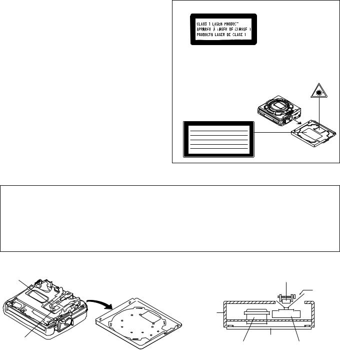
Precaution to be taken when replacing and servicing the Laser Pickup.
The AEL (Accessible Emission Level) of Laser Power Output for this model is specified to be lower than Class I Requirements. However, the following precautions must be observed during servicing to protect your eyes against exposure to the laser beam.
(1)When the cabinet has been removed, the power is turned on without a compact disc, and the Pickup is on a position outer than the lead-in position, the Laser will light for several seconds to detect a disc. Do not look into the Pickup Lens.
(2)The Laser Power Output of the Pickup inside the unit and replacement service parts have already been adjusted prior to shipping.
(3)No adjustment to the Laser Power should be attempted when replacing or servicing the Pickup.
(4)Under no circumstances look directly into the Pickup Lens at any time.
(5)CAUTION - Use of controls or adjustments, or performance of procedures other than those specified herein may result in hazardous radiation exposure.
CAUTION
 This Portable MiniDisc Recorder is classified as a CLASS 1 LASER product.
 The CLASS 1 LASER PRODUCT label is located on the bottom.
 Use the portable minidisc recorder only in accordance with the instructions given in this manual and do not attempt to interfere with the interlock switch or make any other adjustment as this may result in exposure to hazardous radiation.
Laser Diode Properties  Material: GaAIAs
 Wavelength: 785 nm
 Pulse time:
Read mode; 0.8 mW Continuous Write mode; max. 10 mW 0.5S
min. cycle 1.5S Repetition
CAUTION - INVISIBLE LASER RADIATION WHEN OPEN AND INTERLOCKS DEFEATED
AVOID EXPOSURE TO BEAM .
VARNING - OSYNLIG LASERSTRÅLNING NÄR DENNA DEL ÄR ÖPPNAD OCH SPÄRRAR ÄR URKOPPLADE. STRÅLEN ÄR FARLIG.
ADVARSEL - USYNLIG LASERSTRÅLING NÅR DEKSEL ÅPNES OG SIKKERHEDSLÅS
BRYTES. UNNGÅ EKSPONERING FOR STRÅLEN.
VARO! AVATTAESSA JA SUOJALUKITUS OHITETTAESSA OLET ALTTIINA
NÄKYMÄTÖN LASERSÄTEILYLLE. ÄLÄ KATSO SÄTEESEN.
VARNING - OSYNLIG LASERSTRÅLING NÄR DENNA DEL ÄR ÖPPNAD OCH SPÄRREN ÄR URKOPPLAD. BETRAKTA EJ STRÅLEN.
ADVARSEL - USYNLIG LASERSTRÅLING VED ÅBNING NÅR SIKKERHEDSAFBRYDERE
ER UDE AF FUNKTION. UNDGÅ UDSETTELSE FOR STRÅLING.
(Illustration: MD-MS722W)
Precaution to be taken when replacing and servicing the laser pickup.
The following precautions must be observed during servicing to protect your eyesagainst exposure to the laser.
Warning of possible eye damage when repairing:
If the AC adaptor or batteries are connected when the top houising (disc cover) of the unit is removed, and the PLAY key is pressed, the laser will light up during docus access (2-3 seconds). (Fig. 2-1) During the operation, the laser will lesk from the opening btween the magnetic head and the mechanical chassis (Fig. 2-2). In order to protect your eyes, you most not look at the laser durnd repaor. Before repaoring be sure to disconnect the AC adaptor and remove the batteries.
Magnet head |
Magnet Head |
|
Lasar Beam
Mechanism |
|
Chassis |
|
Optical pick-up |
Main PWB |
|
|
Disc motor |
Optical Pick-Up |
Disc cover |
|
Figure 2-1 |
Figure 2-2 |
– 2 –

MD-MS722/C/W/MS721W
FOR A COMPLETE DESCRIPTION OF THE OPERATION OF THIS UNIT, PLEASE REFER TO THE OPERATION MANUAL.
SPECIFICATIONS
 General
Power source: |
DC 3.6 V (rechargeable lithium-ion |
||
(MS722/MS722C) |
battery x 1) |
||
|
DC 5 V (AC adaptor) |
||
|
AC 120V, 60 Hz |
|
|
|
DC 3.4V: Battery case |
||
|
(commercially available, "AA" |
||
|
size, alkaline battery x 1) |
||
|
DC 4.5V: Separately available car adaptor, |
||
|
AD-CA20X |
||
|
(for cars with a 12-24V DC |
||
|
negative earth electrical system) |
||
Power source: |
DC 3.6 V (rechargeable lithium-ion |
||
(MS722W/MS721W) |
battery x 1) |
||
|
DC 5 V (AC adaptor) |
||
|
AC 110 - 240V, 50/60 Hz |
||
|
DC 3.4V: Battery case |
||
|
(commercially available, "AA" |
||
|
size, alkaline battery x 1) |
||
|
DC 4.5V: Separately available car adaptor, |
||
|
AD-CA20X |
||
|
(for cars with a 12-24V DC |
||
|
negative earth electrical system) |
||
Power consumption: |
7 W (AC adaptor) |
|
|
(MS722/MS722C) |
|
|
|
Power consumption: |
0.15A (AC adaptor) |
|
|
(MS722W/MS721W) |
|
|
|
Output power: |
RMS; 20 mW (10 mW + 10mW) |
||
|
(0.2% T.H.D.) |
|
|
Charging time: |
Approx. 3 hours |
|
|
|
(When using the AC adaptor included |
||
|
with the unit) |
|
|
Battery life: |
|
|
|
|
|
|
|
When using the |
When using one, |
|
When using one, |
commerically available, |
|
commercially available, |
|
rechargeable battery (fully |
|
||
high capacity, "AA" size, |
|
high capacity, "AA" size |
|
charged) included with the |
|
||
alkaline batteries (in the |
|
batteries with the recharge- |
|
unit |
|
||
battry case) |
|
able battery (fully charged) |
|
|
|
||
|
|
|
|
Continuous recording: |
Continuous recording: |
|
Continuous recording: |
Approx. 8 hours |
Approx. 3 hours |
|
Approx. 11 hours |
|
|
|
|
Continuous play: |
Continuous play: |
|
Continuous play: |
Approx. 10 hours |
Approx. 6 hours |
|
Approx. 16 hours |
|
|
|
|
 The continuous recording time is for analogue input when the volume level is set to "VOL 0".
 The continuous play time shows the value when the volume level is set to "VOL 15".
 The above values are the standard values when the unit is charged and used at an ambient temperature of 20oC.
 The operating time when using alkaline batteries may be different, depending on the type and manufacturer of the batteries, and on the operating temperature.
Input sensitivity: |
|
|
|
|
Recording level |
Reference input level |
Input impedance |
||
|
||||
|
|
|
|
|
|
MIC H |
0.25 mV |
10 k ohms |
|
|
|
|
|
|
|
MIC L |
2.5 mV |
10 k ohms |
|
|
|
|
|
|
|
LINE |
100 mV |
20 k ohms |
|
|
|
|
|
Output level: |
|
|
Specified |
Maximum |
Load |
|
(MS722/MS722C) |
|
|
||||
|
|
output |
output level |
impedance |
||
|
|
|
|
|||
|
|
|
|
|
|
|
|
|
Headphones |
— |
10 mW + |
16 ohms |
|
|
|
|
|
|
10 mW |
|
|
|
|
|
|
|
|
|
|
LINE |
|
300 mV |
— |
10 kohms |
|
|
|
|
(-12dB) |
|
|
Output level: |
|
|
|
|
|
|
|
|
|
|
|
|
|
|
|
|
Specified |
Maximum |
Load |
|
(MS722W/ |
|
|
|
output |
output level |
impedance |
MS721W) |
|
|
|
|
|
|
|
Headphones |
— |
10 mW + |
32 ohms |
||
|
|
|||||
|
|
|
|
|
10 mW |
|
|
|
|
|
|
|
|
|
|
LINE |
|
300 mV |
— |
10 kohms |
|
|
|
|
(-12dB) |
|
|
|
|
|
|
|
|
|
Dimensions: |
|
Width: 3-7/16" (87.0 mm) |
|
|||
|
|
|
Height: 1-1/16" (26.7 mm) |
|
||
|
|
|
Depth: 3-1/4" (81.5 mm) |
|
||
Weight: |
|
0.49 lbs. (220 g) with rechargeable |
||||
|
|
|
battery |
|
|
|
Input socket: |
|
Line/optical digital, microphone |
||||
|
|
|
(powered by the main unit) |
|
||
Output socket: |
|
Headphones (impedance: 19 ohms)/ |
||||
(MS722/MS722C) |
|
remote control unit |
|
|||
Output socket: |
|
Earphones (impedance: 32 ohms)/ |
||||
(MS722W/MS721W) |
remote control unit |
|
||||
 MiniDisc Recorder
Type: |
Portable MiniDisc recorder |
Signal readout: |
Non-contact, 3-beam semi-coductor |
|
laser pick-up |
Audio channels: |
Stereo 2 channels/monaural (long- |
|
play mode) 1 channel |
Frequency response: |
20 - 20,000 Hz (± 3 dB) |
Rotation speed: |
Approx 400 - 900 rpm |
Error correction: |
ACIRC (Advanced Cross Interleave |
|
Reed-Solomon Code) |
Coding: |
ATRAC (Adaptive TRansform |
|
Acoustic Coding), 24-bit computed |
|
type |
Recording method: |
Magnetic modulation overwrite |
|
method |
Sampling frequency: |
44.1 kHz (32 kHz and 48 kHz signals |
|
are converted to 44.1 kHz, and then |
|
recorded.) |
Wow and flutter: |
Unmeasurable (less than ±0.001% |
|
W.peek) |
Specifications for this model are subject to change without prior notice
– 3 –
MD-MS722/C/W/MS721W
NAME OF PARTS
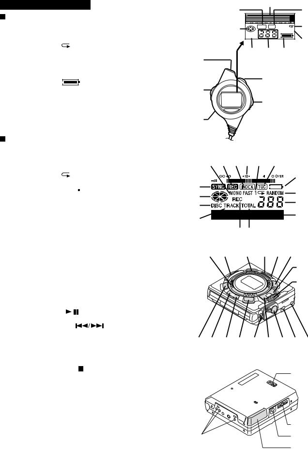
MD-MS722/MS722C/MS722W |
1 |
2 |
|
3 |
||
Remote control unit |
|
|
||||
|
|
|
|
|||
1. |
Synchro Recording Indicator |
6 |
SYNC REC |
1 |
4 |
|
2. |
Character/Time Information Indicator |
|||||
|
RANDOM |
|||||
3. |
Record Indicator |
TOTAL |
|
|
5 |
|
|
|
|
||||
|
|
|
|
|||
4. |
Repeat Indicator: |
7 |
8 |
9 |
|
|
5. |
Random Indicator |
|
||||
6. |
Disc Mode Indicator |
10 |
|
|
|
|
7. |
Total Track Number Display |
|
|
|
|
|
8. |
Track Number Indicator |
|
13 |
|
|
|
9. |
Battery Indicator: |
11 |
|
|
||
10. |
Headphones Jack (MS722/MS722C) |
|
|
|
||
|
|
|
|
|||
10. |
Earphones Socket (MS722W) |
|
14 |
|
|
|
11. |
Display/Volume Shuttle Switch |
|
|
|
||
12. |
Hold Switch |
12 |
|
|
|
|
13. Play/Pause/Fast Reverse/ Fast Forward Shuttle Switch |
|
|
|
|||
14. |
Stop/Power Off/Bass/Play Mode Shuttle Switch |
|
|
|
||
|
|
|
|
|||
Main unit
1.Monaural Long-Play Mode Indicator
2.Record Indicator
3. |
Index Indicator |
1 |
2 |
3 |
4 |
5 |
|
6 |
|
|
|
|
|||||||
4. |
Level Meter |
|
|
|
|
|
|||||||||||||
|
|
|
|
|
|
|
|
|
|
|
|
||||||||
5. |
Repeat Indicator: |
|
|
|
|
|
|
|
|
|
|
|
7 |
||||||
|
|
|
|
|
|
|
|
|
|
|
|||||||||
6. |
TOC Indocator |
11 |
|
|
|
|
|
|
|
|
|
|
|||||||
|
|
|
|
|
|
|
|
|
|
||||||||||
|
|
|
|
|
|
|
|
|
|
|
|||||||||
7. |
Battery Indicator: |
|
|
|
|
|
|
|
|
|
|
|
|
|
|
|
|
8 |
|
8. |
Random Indicator |
12 |
|
|
|
|
|
|
|
|
|
|
|||||||
|
|
|
|
|
|
|
|
|
|
||||||||||
|
|
|
|
|
|
|
|
|
|
9 |
|||||||||
9. |
Track Number Indicator |
13 |
|
|
|
|
|
|
|
|
|
|
|||||||
10. |
Character/Time Information Indicator |
14 |
|
|
|
|
|
|
|
|
|
|
10 |
||||||
11. |
Synchro Recording Indicator |
|
|
|
|
|
|
|
|
|
|
||||||||
|
|
|
|
|
|
|
|
|
|
|
|||||||||
12. |
Disc Mode Indicator |
|
|
|
15 16 |
|
|
|
|
|
|
|
|||||||
13. |
Disc Name Indicator |
|
|
|
|
|
|
|
|
|
|
||||||||
14.Track Name Indicator
15.Remaining Recording Time Indicator
16. |
Total Track Number Display |
17 18 |
19 20 21 22 |
17. |
Jog Dial |
|
23 |
18. |
Record/Track Mark Button |
|
24 |
19. |
Volume/Name Select Buttons: – |
|
|
20. |
Display/Lowercase Characters Button |
|
|
21. |
Character Button |
|
|
22. |
Volume/Name Select Buttons: + |
|
|
23. |
Play/Pause Button: |
|
|
24. Fast Reverse/Fast Forward/Recording Level Control/ |
|
|
|
|
Cursor Shuttle Switch: |
|
|
25. |
Edit/Auto Mark/Time Mark Button |
|
|
26. |
Mode/Insert Button |
25 26 27 28 29 30 31 32 33 |
|
27. |
Bass/Delete Button |
||
28. |
Enter/Fast Play/Synchro Button |
|
|
29. |
Handstrap Attachment Eye |
|
|
30. |
Stop/Power Off Button: /:OFF |
|
34 |
31. |
Eject Lever |
|
|
32. |
Optical/Line Input Jack (MS722/MS722C) |
|
|
32.Optical/Line Input Socket (MS722W)
33.Microphone Input Jack (MS722/MS722C)
33. Microphone Input Socket (MS722W)
34. |
Hold Switch |
|
36 |
||
35. |
Battery Case Connection Terminals |
|
|||
36. |
Headphones Jack (MS722/MS722C) |
35 |
37 |
||
36. |
Earphones Socket (MS722W) |
||||
|
|||||
37. |
5V |
DC Input Jack (MS722/MS722C) |
|
38 |
|
37. |
5V |
DC Input Socket (MS722W) |
|
||
|
|
||||
38. |
Rechargeable Lithium-lon Battery Compartment |
|
|
||
– 4 –
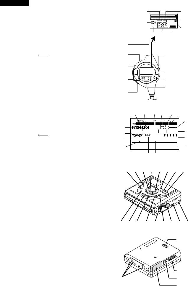
MD-MS721W
 Remote control unit
1.Synchro Recording Indicator
2.Character/Time Information Indicator
3.Record Indicator
4.Repeat Indicator: 
5.Random Indicator
6.Disc Mode Indicator
7.Total Track Number Display
8.Track Number Indicator
9.Battery Indicator: 


10.Earphones Socket
11.Hold Switch
12.Play Mode Button
13.Volume Buttons: +, –
14.Bass Button
15.Display Button
16.Play/Pause Button: 


17.Stop/Power Off Button: 
18.Fast Reverse/Fast Foward Buttons: 


 Main unit
1.Monaural Long-Play Mode Indicator
2.Record Indicator
3.Level Meter
4.Repeat Indicator: 
5.TOC Indocator
6.Battery Indicator: 


7.Random Indicator
8.Track Number Indicator
9.Character/Time Information Indicator
10.Synchro Recording Indicator
11.Disc Mode Indicator
12.Disc Name Indicator
13.Track Name Indicator
14.Remaining Recording Time Indicator
15.Total Track Number Display
16.Mode/Insert Button
17.Record/Track Mark Button
18.Fast Reverse/Recording Level Control/ Cursor Button: 
19.Play/Pause Button: 


20.Fast Forward/Recording Level Control/ Cursor Button: 

21.Display/Lowercase Characters Button
22.Volume/Name Select Buttons: –
23.Volume/Name Select Buttons: +
24.Bass/Delete Button
25.Character Button
26.Enter/Fast Play/Synchro Button
27.Edit/Auto Mark/Time Mark Button
28.Handstrap Attachment Eye
29.Stop/Power Off Button:  /:OFF
/:OFF
30.Eject Lever
31.Optical/Line Input Socket
32.Microphone Input Socket
33.Hold Switch
34.Battery Case Connection Terminals
35.Earphones Socket
36.5V DC Input Socket
37.Rechargeable Lithium-lon Battery Compartment
MD-MS722/C/W/MS721W
1 |
2 |
|
3 |
|
|
||
6 |
SYNC REC |
1 |
4 |
|
RANDOM |
||
TOTAL |
|
|
5 |
|
|
|
|
7 |
8 |
9 |
|
10 |
|
|
|
11 |
15 |
|
|
12
16
13 17
18
14
1 |
2 |
3 |
4 |
5 |
6
10
11


 7
7
12


 8
8
13


 9
9
14 15
16 17 18 19 20 21 22 23
24 25 26 27 28 29 30 31 32
33
35
34 36
37
– 5 –

– 6 –
POWER SOURCE
This unit can be used with 4 different power sources: a rechargeable battery, an AC adaptor, a battery case, and a separately available car adaptor (AD-CA20X).
1
OPEN |
OPEN |
|
2
Mark
OPEN
4
To the DC IN 5V socket
DC IN 5V
Insert securely, all the way in.
MS722W Except for Australia/
New Zealand/MS721W: AC 110-240V, 50/60 Hz
MS722W For Australia/New Zealand:
AC 110-240V, 50/60 Hz
Notes:
After charging has been completed, the AC adaptor may be left connected. (For example, when charging at night) If the rechargeable battery is in the unit, it will be charged, even whilst operating the unit. (Float charge)
Rechargeable battery power
When the rechargeable battery is used for the first time or when you want to use it after a long period of disuse, be sure to charge it fully.
1 Open the rechargeable battery compartment cover.
2 Insert the rechargeable battery.  Insert the side with the arrow first.
3 Close the rechargeable battery compartment cover.
4 Plug the AC adaptor into the AC socket, and then insert the plug on the AC adaptor lead into the DC IN 5V socket.
About 4 seconds later,  ” will flash and the battery will begin charging. Battery charging will be complete in 3.0 hours. When the charging is complete,
  ” will go out.
Do not force open the rechargeable battery cover too wide.
When the AC adaptor plug is inserted and a MiniDisc has already been inserted, playback may start automatically.
In this case, press the  / :OFF button twice to turn the power off.
CONVENIENT OPERATION OF THE UNIT
Checking the remaining amount of battery charge
The remaining amount of battery charge is shown by the battery indicator (  ) during operation.
Battery indicator
< How to read the battery indicator >
When the battery is |
|
Charging is |
||||
completely charged |
|
needed. |
||||
|
|
|
|
|
|
|
|
|
|
|
|
|
|
|
|
|
|
|
|
|
|
|
|
|
|
|
|
When the battery needs charging, it is impossible to start recording or editing.
When the battery is completely discharged, the whole battery indicator will flash. Recharge the battery or replace the alkaline battery with a new one.
When the battery has run completely out, “BATT EMPTY” (main unit) and “Lo BATT” (remote control unit) will appear. Then, the power will be disconnected automatically.
Notes:
When using the unit with an alkaline battery or a rechargeable battery, the battery indicator will not display correctly the remaining capacity for approximately 20 seconds after the power has been turned on.
When the AC adaptor included with this unit or a separately available car adaptor is used, the battery indicator will not be shown.
The number of bars shown in the battery indicator may increase or decrease, depending on the operation being performed. This is normal.
When the rechargeable battery and the alkaline battery are used at the same time, the rechargeable battery is used first, and then the alkaline battery.
Since the battery indicator shows the remaining amount of the particular battery being used, the number of bars will increase when the unit switches to the alkaline battery.
RECORDING USING THE OPTICAL DIGITAL CABLE
There are cases where digital recording may be impossible.
In the following cases digital recording is impossible, even if you are using digital cables.
When you attempt to make a new digital recording from a track that was digitally recorded on a MiniDisc
MiniDiscs are designed so that only first generation digital copies can made, further digital copies are prevented by the SCMS (Serial Copy Management System).
Playback |
Digital cable |
Recording |
CD player, MD player, etc.
Digitally recorded MiniDisc
Playback |
Digital cable |
Recording |
|
|
|
Analogue recording is possible.
MS722/C/W/MS721W-MD
MANUAL OPERATION
(Illustration: MD-MS722W)

– 7 –
TROUBLESHOOTING
Moisture condensation
In the following cases, condensation may form inside the unit.
Shortly after turning on a heater. When the unit is placed in a room where there is excessive steam or moisture.
When the unit is moved from a cool place to a warm place.
When the unit has condensation inside, the disc signals cannot be read, and the unit may not function properly.
If this happens, remove the disc.
The condensation should evaporate in approximately 1 hour. The unit will then function properly.
Many potential “problems” can be resolved by the owner without calling a service tech nician. If something seems to be wrong with this product, check the following before calling your authorised SHARP dealer or service centre.
PROBLEM |
CAUSE |
|
|
The unit does not turn on.
No sound is heard from the earphones.
 Is the AC adaptor disconnected?
 Is the battery exhausted?
 Is the unit in the hold mode?
 Has condensation formed inside the unit?
 Is the unit being influenced by mechanical shock or by static electricity?
 Is the volume set too low?
 Is the remote control unit or the earphones plugged in?
 Are you trying to play a MiniDisc with data on it instead of a MiniDisc containing music?
When the operation |
|
Is the unit in the hold mode? |
buttons are pressed, |
|
Is the battery exhausted? |
the unit does not |
|
Is the remote control unit plug or the earphone plug |
respond. |
|
inserted firmly? |
Some sounds are |
|
Is the battery exhausted? |
|
||
skipped. |
|
Is the unit being subjected to excessive vibration? |
The MiniDisc cannot |
|
Has the track number or character information been |
|
written on the disc yet? |
|
be ejected. |
|
|
|
Is the unit in the recording or editing mode? |
|
|
|
|
|
|
Is the MiniDisc protected against accidental erasure? |
|
|
Is the unit connected properly to the other equipment? |
|
|
Is the AC adaptor unplugged or did a power failure |
Recording and editing |
|
occur whilst recording or editing? |
are impossible. |
|
Is the unit in the hold mode? |
|
|
Is an optical signal being output from the external |
|
|
equipment? |
|
|
Read the operation manual for the external equipment. |
If trouble occurs
When this product is subjected to strong external interference (mechanical shock, excessive static electricity, abnormal supply voltage due to lightning, etc.) or if it is operated incorrectly, it may malfunction. If such a problem occurs, do the following:
1.Unplug the AC adaptor from the AC socket.
2.Remove the battery.
3.Leave the unit completely unpowered for approximately 30 seconds.
4.Plug the AC adaptor back into the AC socket and retry the operation.
If strange sounds, smell or smoke come out of the unit or an object is dropped into the unit, remove the AC adaptor from the AC socket immediately and contact an authorised SHARP service centre.
MINIDISC SYSTEM LIMITATIONS
MiniDiscs are recorded using a different system than is used for cassette tapes or DAT recordings. Therefore, the following conditions may be encountered, depending on how the disc has been recorded or edited. These are due to system limitations, and should be considered normal.
Even if the maximum recording time of a MiniDisc has not been reached, “DISC FULL” or “TOC FULL” may be displayed.
Even if the number of tracks and the recording time have not reached the limit, “DISC FULL” may be displayed.
Even if several short tracks are erased, the remaining recording time may not show an increase.
Two tracks may not be combined in editing.
The total of the recorded time and time remaining on a disc may not add up to the maximum possible recording time.
When recorded tracks are played back using the cue and review operations, some sounds may be skipped.
A track number can be created in the middle of a track.
When the number of tracks used reaches the limit, regardless of the remaining recording time, further recording will be impossible. (Maximum number of tracks: 254) If a MiniDisc has been recorded or
edited repeatedly or if a MiniDisc has scratches on it, it may not be possible to record the maximum number of tracks on it.
If there are scratches on a disc, the unit will automatically avoid recording in those areas. The recording time will be reduced.
When the remaining recording time of a disc is displayed, short tracks less than 12 seconds long may not be included in the total.
For MiniDiscs on which repeated recording and editing operations were performed, the COMBINE function may not work.
A cluster (about 2 seconds) is normally the minimum unit of recording. So, even if a track is less than 2 seconds long, it will use about 2 seconds of space on the disc. Therefore, the time actually available for recording may be less than the remaining time displayed.
If there are scratches on discs, those sections will be automatically avoided (no recording will be placed in those sections). Therefore, the recording time will be reduced.
For MiniDiscs on which repeated recording and editing were performed, some sounds may be skipped whilst cueing and reviewing.
If there are scratches or dust on a MiniDisc, the track numbers following that track will be increased by one.
MS722/C/W/MS721W-MD
– 8 –
ERROR MESSAGES
Error messages |
Meaning |
BATT EMPTY |
The battery run down. |
|
|
(Lo BATT) |
|
BLANK DISC |
Nothing is recorded. |
(BLANK) |
|
Can't COPY
(Not REC)
Can't EDIT
Can't REC
(Not REC)
Can't WRITE
DEFECT (DEFECT)
 No copy can be made because of the SCMS copyright system.
 A track cannot be edited.
 Recording cannot be performed correctly due to vibration or shock in the unit.

 Editing is impossible.
  The disc is scratched.
Din UNLOCK (UNLOCK)
DISC ERROR
(E-DISC)
DISC FULL
HOLD (HOLD)
LOCKED
LOCK ERROR
NO DISC
PB DISC
PROTECTED
POWER ?
SORRY (SORRY)
SYSTEM ERR
(E-SYS)
TEMP OVER
(E-TEMP)
TOC ERROR
(E-TOC)
TOC FULL
Tr. Protect
U TOC ERROR
(E-UTOC)
? DISC (?DISC)
 Poor connection of the digital cable.
 The disc is damaged.
 The disc is out of recording space.
 The unit is in the hold mode.
 The EJECT lever was moved during recording or editing.
 A disc has not been loaded.
 The disc is write protected.
You tried to record on a playbackonly disc.
 Improper power is being supplied.
 Since a track number is currently being located or written to, the unit cannot accept your command.
 You have come to the conclusion that the unit is out of order.
 The temperature is too high.
 A large portion of the disc has been damaged.
 There is no space left for recording character information (track names, disc names, etc.).
 The track has been protected from being erased.
 A large portion of the disc has been damaged.
 There is an error in the recorded signal.
 A disc which contains data other than music was played.
 There is an error in the signal from the disc.
Remedy
 Charge the rechargeable battery or replace the alkaline battery (or use the AC adaptor for power).
 Replace the disc with a recorded disc.
 Record using the analogue cable.
 Change the stop position of the track and then try editing it.
 Re-record or replace it with another recordable disc.
 Check the number of tracks.
 If the sound you hear is not right, try recording again.
Replace the disc with another recordable disc.
 Connect the digital cable securely.
 Reload the disc or replace it.
 Replace it with another recordable disc.
 Return the HOLD switch to its original position.
 Turn off the power and remove the MiniDisc.
 Load a disc.
 Move the write protection knob back to its original position.
 Replace it with a recordable disc.
 Use one of the specified power sources.
 Wait for a while and try the operation again.
 To have it repaired, go to the distributor where you purchased the unit.
 Turn off the power, and wait for a while.
 Replace it with another recorded disc.
 Replace it with another recordable disc.
 Edit the track with the device on which it was recorded.
 Replace it with another recorded disc.
 Erase all of the signal errors, and then try recording again.
 A disc which contains non-music data cannot be played.
 Replace it with another recorded disc.
MS722/C/W/MS721W-MD
( ): Error messages seen on the remote control.
PORTABLE MINIDISC RECORDER
Quick Guide/Guía rápida MD-MS722
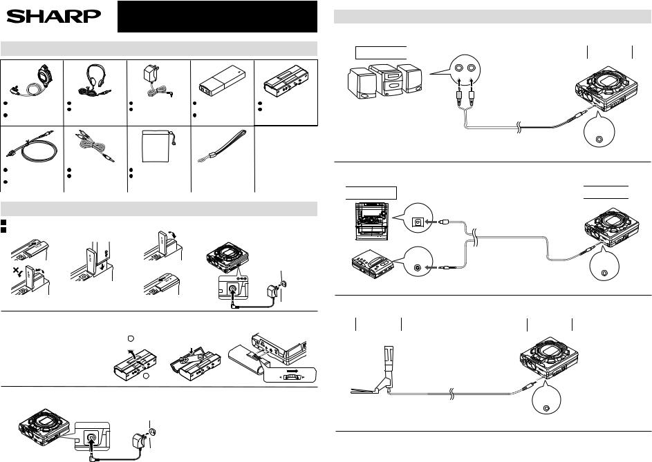
1 Check the supplied accessories / Compruebe los accesorios suministrados
– 9 –
Remote Control Unit |
Headphones x 1 |
AC Adaptor x 1 |
x 1 |
Auriculares x 1 |
Adaptador de CA x 1 |
Controlador remoto |
|
|
x 1 |
|
|
Optical Digital Cable |
Analog Cable x 1 |
Carrying Bag x 1 |
|
x 1 |
Cable analógico x 1 |
Caja para el |
|
Cable óptico digital x |
|
|
transporte x 1 |
1 |
|
|
|
2 Power source / Alimentación |
|
||
Rechargeable battery power |
|
||
Alimentación de la batería recargable |
|
||
1 |
2 |
4 |
3 |
OPEN |
|
|
OPEN |
|
|
|
|
|
|
OPEN |
|
OPEN |
|
|
OPEN |
|
|
|
|
Rechargeable |
Battery Case x 1 |
Lithium-Ion Battery x 1 |
Caja de la pila x 1 |
Batería recargable de |
|
litio-ion x 1 |
|
 Handstrap x 1
 Correa para la muñeca x 1
DC IN 5V |
∙ AC 120V, |
|
60Hz |
|
∙ 120V CA, |
|
60Hz |
 Alkaline battery power
 Alimentación de la pila alcalina
 Make sure that a fully charged rechargeable battery is inserted.
 Do not use the unit if it only has an alkaline battery in it.
 Asegúrese de que se ha insertado una batería completamente cargada.
 No emplee el aparato si sólo tiene una pila alcalina instalada.
|
|
|
∙ Back of the MD recorder |
|
|
|
|
∙ Parte posterior de la |
|
|
|
|
grabadora de MD |
|
1 |
2 Open. |
2 |
3 |
|
|
Abrir. |
|
|
|
|
1 Press. |
|
RELEASE |
LOCK |
|
Pulsar. |
|
|
|
 AC power
 Alimentación de CA
DC IN 5V
∙ AC 120V, 60Hz
∙ 120V CA, 60Hz
3 Connection / Conexión
 Analog recording
 Grabación analógica
Playback side
Lado de reproducción
|
L |
R |
|
(RIGHT) |
(LEFT) |
|
(DERECHO) |
(IZQUIERDO) |
∙ |
To the line output jacks |
|
∙ |
on a stereo |
|
A los enchufes de |
|
salida de línea de un
equipo estéreo
∙ Analog cable included with this unit
∙ Cable analógico suministrado con este
 Digital recording
 Grabación digital
Playback side
Lado de reproducción
DIGITAL OUT
OPTICAL OUT
 Microphone
 Micrófono
Stereo microphone
Micrófono estéreo
∙Optical digital cable (supplied)
∙Cable óptico digital (suministrado)
∙Optical digital cable (AD-M2DC, available separately)
∙Cable óptico digital (AD-M2DC, disponible por separado)
Recording side
Lado de grabación
MIC IN
PLUG IN
POWER
Recording side
Lado de grabación
OPTICAL/
LINE IN
Recording side
Lado de grabación
OPTICAL/
LINE IN
MS722/C/W/MS721W-MD ONLY) MS722-(MD GUIDE QUICK
– 10 –
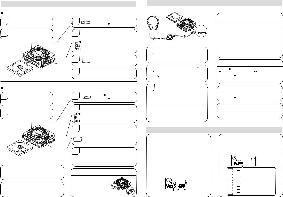
4 Recording / Grabación
 Recording from CDs or MDs (Synchro recording)
Grabación de discos compactos o minidiscos (Grabación sincronizada)
1 |
Connect the external equipment. |
3 |
Conecte el equipo externo. |
||
2 |
Insert a recordable MiniDisc. |
4 |
Inserte un minidisco grabable. |
5
6
 Recording from the microphone (Mic synchro recording)
Press the  REC button.
REC |
Pulse el botón REC. |
|
While playing sound from the external equipment connected to this unit, move the shuttle switch up or down to adjust the recording level.
Mientras se reproduce el sonido del equipo externo conectado a este aparato, mueva el selector de mando de lanzadera hacia arriba o abajo para ajustar el nivel de grabación.
Press the ENTER/SYNC button.
ENTER
SYNC Pulse el botón ENTER/SYNC.
Begin playback on the source equipment.
Inicie la reproducción en el equipo fuente.
Grabación de un micrófono (Grabación sincronizada con micrófono)
1 |
Connect the stereo microphone to |
the MIC IN jack. |
|
|
Conecte el micrófono estéreo al |
|
enchufe MIC IN del aparato principal. |
2 |
Insert a recordable MiniDisc. |
Inserte un minidisco grabable. |
To stop recording:
Para detener la grabación:
Press the  /:OFF button.
Pulse el botón  /:OFF.
After recording:
Después de la grabación:
Press the  /:OFF button while in the stop mode.
Pulse el botón  /:OFF estando en el modo de parada.
3 |
|
Press the REC button. |
REC |
Pulse el botón REC. |
|
4 |
Move the shuttle switch up or down to adjust |
|
the recording level. |
||
|
Mueva el selector de mando de lanzadera hacia |
|
|
arriba o abajo para ajustar el nivel de grabación. |
|
5 |
Press the ENTER/SYNC button to select the |
|
synchro recording level. (This level can be |
||
|
changed, even while recording.) |
|
|
Pulse el botón ENTER/SYNC para seleccionar el |
|
ENTER nivel de la grabación sincronizada. (Este nivel |
||
SYNC |
podrá cambiarse incluso durante la grabación.) |
|
|
||
6 |
When a noise, such as a person speaking, is |
|
picked up by the microphone, recording will |
||
begin automatically.
Cuando el micrófono capte un ruido, el de una persona que hable por ejemplo, la grabación empezará automáticamente.
To remove the MiniDisc:
Para extraer el minidisco:
Turn off the power and move the EJECT lever in the direction indicated by the arrow.
Desconecte la alimentación y mueva la palanca EJECT en el sentido indicado por la flecha.
5 Playing a MiniDisc / Reproducción de un minidisco
 REMOTE
1 |
Insert the headphones plug firmly into the |
headphones jack on the remote control unit. |
|
|
Inserte firmemente la clavija de los auriculares |
|
en el enchufe de auriculares del controlador |
|
remoto. |
2 |
Plug the remote control unit into the |
jack |
on the main unit. Push the plug all the way in. |
||
|
Enchufe el controlador remoto en el enchufe |
|
|
del aparato principal. Empuje completamente |
|
|
hacia adentro la clavija. |
|
3 |
Load a MiniDisc in the direction indicated by |
the arrow on the MiniDisc, with the label side |
facing up.
Cargue un minidisco en el sentido indicado por la flecha del minidisco, con el lado de la etiqueta hacia arriba.
 The power will be turned on automatically, and playback will start from the first track. (Auto-play function)
 La alimentación se conectará automáticamente, y la reproducción empezará desde la primera pista. (Función de reproducción automática)
Playback does not start when a MiniDisc is inserted:
La reproducción no empieza cuando se inserta un minidisco:
Press the 
 button.
In the following cases, the auto-play function will not work.  When the recordable MiniDisc write protection tab is
closed
 When the auto-play function has been canceled
Pulse el botón 
 .
.
En los casos siguientes, la función de reproducción automática no se activará.
 Cuando esté cerrada la lengüeta de protección contra escritura del minidisco grabable
 Cuando haya sido cancelada la función de reproducción automática
To interrupt playback:
Para interrumpir la reproducción:
Press the |
|
|
button during playback. |
|
|||
To resume playback, press the |
|
|
button again. |
||||
|
|||||||
Pulse el botón |
|
durante la reproducción. |
|||||
|
|||||||
 Para reanudar la reproducción, pulse de nuevo el botón

 .
.
To stop playback:
Para detener la reproducción:
Press the  /:OFF button.
Pulse el botón /:OFF.
To turn off the power:
Para desconectar la alimentación:
Press the  /:OFF button while in the stop mode.
Pulse el botón  /:OFF estando en el modo de parada.
6 Sound control / Control del sonido
Adjust the volume. From the main unit:
Press the + button to increase the volume and the – button to decrease the volume.
From the remote control unit:
Move the shuttle switch up once to increase the volume, and move it down once to decrease the volume.
Ajuste el volumen.
Desde el aparato principal:
Pulse el botón + para aumentar el volumen y el botón – para reducirlo.
Desde el controlador remoto:
Mueva el selector de mando de lanzadera una vez hacia arriba para aumentar el volumen, y muévalo hacia abajo para reducirlo.
∙Volume (0 - 30)
∙Volumen (0 - 30)
Adjust the bass level.
Each time the BASS button is pressed, the tone will be switched as follows:
Ajuste el nivel de los graves.
Cada vez que pulse el botón BASS, el tono cambiará de la forma siguiente:
BASS 1 Bass sounds are emphasized slightly. BASS 2 Bass sounds are emphasized more. BASS 3 Bass sounds are emphasized even more.
BASS OFF Bass emphasis is canceled.
BASS 1 Los sonidos graves se realzan ligeramente.
BASS 2 Los sonidos graves se realzan más.
BASS 3 Los sonidos graves se realzan aún más.
BASS OFF El realce de los graves se cancela.
MS722/C/W/MS721W-MD
MD-MS722/C/W/MS721W
|
|
DISASSEMBLY |
(A2)x2 |
|
|
|||
Cares before disassembling |
|
|
ø1.4x2mm |
(A2)x1 |
|
|||
|
|
|
ø1.4x2mm |
(B1)x1 |
||||
When assembling the machine after disassembling or |
Bottom Cabinet |
|
||||||
|
ø1.4x2mm |
|||||||
repair, observe the following requirements so as to |
(A2)x1 |
|
|
|||||
|
|
|
||||||
ensure safety and performance. |
|
ø1.4x2.5mm |
|
|
(A1)x1 |
|||
1. Remove the batteries from the machine, and take out the |
|
|
|
|
||||
mini-disc. |
|
|
|
|
|
Pull |
||
2. When assembling after repair, be sure to restore the |
|
|
|
|||||
|
|
|
|
|||||
initial location of wires. |
|
|
|
|
|
|||
Since the screws are small, incorrect fixing may result in |
|
|
|
|
||||
malfunction. |
|
|
Center |
|
|
(A2)x2 |
||
3. When repairing, pay utmost attention to static electricity |
|
|
||||||
|
|
ø1.4x2mm |
||||||
of ICs. |
|
|
Cabinet |
|
|
|
||
|
|
|
|
|
(B1)x2 |
|||
|
|
|
|
|
|
|
||
|
|
|
|
|
Top Cabinet |
ø1.4x2mm |
||
|
|
|
|
|
|
|||
STEP |
REMOVAL |
PROCEDURE |
FIGURE |
|
Figu re 11-1 |
|
||
1 |
Bottom Cabinet |
1. Battery Cover ......... (A1) x1 |
11-1 |
Put the fold on the connector, and |
(C1)x1 |
|||
|
|
2. Screw ..................... (A2) x6 |
|
|||||
|
|
|
apply with the felt. Sagging may |
|||||
|
|
|
ø1.7x2.5mm |
|||||
2 |
Top Cabinet |
1. Screw ..................... (B1) x3 |
11-1 |
result in contact with the sheet metal. |
||||
|
|
|||||||
Felt |
|
|
(B2)x1 |
|||||
|
|
2. Flexble PWB .......... (B2) x2 |
11-2 |
|
Main PWB |
|
||
3 |
Main PWB |
1. Screw .................... (C1) x2 |
11-2 |
|
|
|
(C1)x1 |
|
|
|
2. Flexble PWB ......... (C2) x2 |
|
|
|
|
ø1.7x2.5mm |
|
|
|
3. Soldering ............... (C3) x4 |
|
|
|
|
(B2)x1 |
|
4 |
Mechanism Unit |
1. Raise the rear part, and remove |
11-3 |
Pull |
|
Pull |
Pull |
|
Pull |
Pull |
|
||||||
|
|
in the arrow direction. |
|
|
|
|||
|
|
|
|
Pull |
|
|
||
|
|
|
|
|
|
|
||
(Illustration: MD-MS722) |
|
|
|
(C3)x3 |
||||
|
|
|
|
|
|
|||
|
|
|
|
(C2)x1* |
(C2)x1 |
|
Top Cabinet |
|
|
|
|
|
|
|
|||
Flexble PWB for |
(C3)x1 |
|
optical pickup |
||
|
ø1.4x2.5mm
Cares when servicing:
Be sure to use the screw with washer (Part code: LX-BZ0822AFFC,
Distribution code: 124 970 0187). If a screw of different length is used by mistake, MD ejection may be disabled.
Figure 11-4
Caution:
Carefully handle the main PWB and flexible PWB. After removing the flexible PWB (*1) for the optical pickup from the connector, do not touch directly the front end of flexible PWB with your hand so as to prevent damage of optical pickup by static electricity.
Figure 11-2
Mechanism Unit
Figure 11-3
INSTALLING THE TOP CABINET
Insert the key flexible PWB at first into the clearance of center cabinet.
Do not allow rise of upper cabinet.
Figure 11-5 |
Figure 11-6 |
– 11 –
MD-MS722/C/W/MS721W
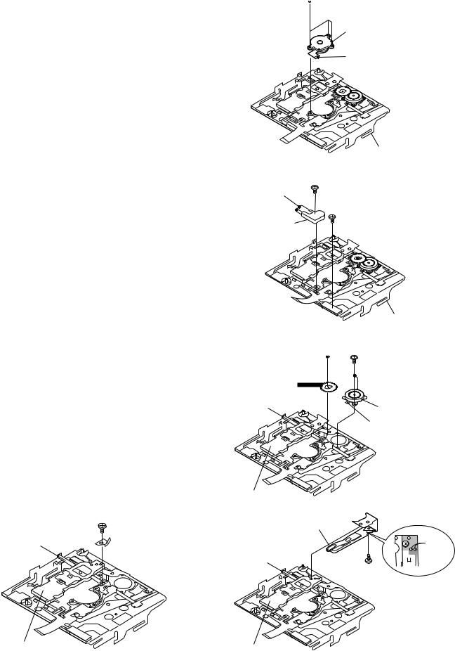
REMOVING AND REINSTALLING THE MAIN PARTS
Remove the mechanism according to the disassembling methods 1 to 3. (See Page 11.)
How to remove the spindle motor (See Fig. 12-1.)
1.Remove the solder joint (A1) x 1 of flexible PWB.
2.Remove the screws (A2) x 3 pcs., and remove the spindle motor.
How to remove the lift motor (See Fig. 12-2.)
1.Remove the solder joint (B1) x 2 of slide motor lead wire.
2.Remove the screw (B2) x 1 pc., and remove the flexible PWB.
3.Remove the screw (B3) x 1 pc., and remove the lift motor.
Note:
Take care so that the motor gear is not damaged. (If the gear is damaged, noise is caused.)
How to remove the sled motor (See Fig. 12-3.)
1.Remove the stop washer (C1) x 1 pc., and remove the drive gear (C2) x 1 pc.
2.Remove the solder joint (C3) x 1 of flexible PWB.
3.Remove the screws (C4) x 2 pc., and remove the sled motor.
Note:
Take care so that the motor gear is not damaged.
How to remove the magnetic head (See Fig. 12-4.)
1. Remove the screw (D1) x1 which connects the magnetic head to the head relay flexible PWB, and remove the soldering joint (D2) x2.
Note:
Mount carefully so as not to damage the magnetic head. (If the gear is damaged, noise is caused.)
How to reinstall the optical pickup unit (See Fig. 12-5.)
1.Remove the screw (E1) x 1 pc.
2.Slowly raise the optical pickup.
(E1)x1
ø1.7x2.5mm
Shaft
Pickup Unit
Figure 12-5
– 12 –
 (A2)x3 ø1.4x2.8mm
Spindle Motor
Mechanism Flexible PWB Solder joint
(A1)x1
|
MD Mechanism |
(B1)x2 |
Figure 12-1 |
|
|
Remove the |
(B3)x1 |
solder joint |
ø1.4x5.5mm |
|
(B2)x1 |
Lift Motor |
ø1.4x1.5mm |
|
|
MD Mechanism |
|
Figure 12-2 |
|
(C4)x2 |
Stop Washer |
ø1.4x1.2mm |
(C1)x1 |
|
Drive Gear |
|
(C2)x1 |
|
Shaft |
Sled Motor |
|
(C3)x1 |
|
Mechanism Flexible PWB |
|
Solder joint |
Pickup Unit
Figure 12-3
Magnetic Head
Solder joint
Shaft |
(D2)x2 |
(D1)x1
Ø1.4x1.5mm
Pickup Unit
Figure 12-4

MD-MS722/C/W/MS721W
Test disc |
ADJUSTMENT |
|
MD adjustment needs two types of disc, namely recording disc (low reflection disc) and playback-only disc (high reflection disc).
|
Type |
Test disc |
Parts No. |
|
|
|
|
1 |
High reflection disc |
MMD-110 (TEAC Test MD) |
88GMMD-110 |
|
|
|
|
2 |
Lowreflection disc |
MMD-212 (TEAC Test MD) |
88GMMD-212 |
|
|
|
|
3 |
Low reflection disc |
Recording minidisc |
UDSKM0001AFZZ |
|
|
|
|
Note: Use the low reflection disc on which music has been recorded.
 Entering the TEST mode
1.Setting at port (in standby state, disc-free state or power nonconnected state)
(1)Set the port as follows. TEST1 : "Low"
TEST0 : "High"
(2)Press the PLAY button in the standby state (it is allowed to insert the disc or to connect the power supply).
(3)Test Mode STOP [ _ T E S T _ ]
2.Setting by special button operation (in standby state)
(1)Holding down the DISP button and ENTER button, press the PLAY button.
(2)Normal mode setting initialization (BASS setting, VOL setting, etc.)
(3) |
Indication of microcomputer version for one second [ 7 0 2 A |
f |
X ] (Only Serial No. 811XXXXX) |
||||||||
|
[ |
|
9 0 8 A |
|
f |
X ] (From Serial No. 812XXXXX) |
|||||
|
Microcomputer version |
|
|
|
|
|
|
|
|
|
Destination |
|
|
|
|
|
|
|
|
|
|||
|
|
|
|
|
|
|
EEPROM version |
||||
|
|
|
|
|
|
|
|||||
(4) |
Whole LCD lighting for 2 seconds |
|
|
|
|
|
|||||
(5) |
Test Mode STOP [ _ T E S T _ ] |
|
|
|
|
|
|||||
*When the PLAY button is pressed during indication (3) and (4), the process proceeds to (5).
 Leaving the TEST mode
(1)Press the STOP button in the TEST mode stop state or version indicating state or whole LCD lighting state.
(2)EEPROM rewrite-enable area updating, adjustment error setting (so as to adjust all the items when the power supply is turned on in the normal mode)
(3)Change to standby state
 Shipping setting method
Holding down simultaneously the VOLUME-DOWN key and PLAY key of the set unit without disc, supply the power from the DC IN plug. After the indication "INIT" -> "BYE OK" disappears, release the power supply of DC IN.
 Test Mode
1. |
AUTO 1 Mode |
• Perform preliminary automatic adjustment. |
|
|
• If the combination of mechanism and pickup |
|
|
PWB has been changed, be sure to start from |
|
|
AUTO1. |
2. |
AUTO 2 Mode |
• Perform ATT (attenuator) automatic adjustment. |
|
|
• Perform continuous playback (error rate display, |
|
|
jump test) |
|
|
|
3. |
MANUAL 1 Mode |
• Temperature is displayed. (Updating in real time) |
|
|
• Seeing the displayed adjustment value, perform |
|
|
preliminary manual adjustment. |
|
|
(Error rate indication, jump test) |
|
|
|
4. |
MANUAL 2 Mode |
• Temperature is displayed. (Updating in real time) |
|
|
• Seeing the displayed adjustment value perform |
|
|
manfully the preliminary adjustment. |
|
|
(Error rate indication, jump test) |
|
|
• Continuous playback is performed |
|
|
(error rate display, jump test). |
5. |
RESULT 1 Mode |
• The value adjusted in AUTO1 or MANUAL1 is |
|
|
indicated. |
|
|
• (Execution in servo "OFF" state"). |
6. |
RESULT 2 Mode |
• The value adjusted in AUTO 2 or MANUAL 2 is |
|
|
indicated. |
|
|
• Adjustment value is changed manually. |
|
|
(error rate display, jump test). |
7. |
TEST-PLAY Mode |
• Continuous playback from the specified address |
|
|
is performed. |
|
|
• 1 line, 10 lines or 400 lines manual jump is |
|
|
performed. |
|
|
• C1 error rate display (pit section), ADIP error |
|
|
rate display (groove section) |
|
|
• The temperature correction is performed only when |
|
|
servo start is performed, but the posture correction |
|
|
is not performed during continuous playback. |
|
|
|
8. TEST-REC Mode |
• Continuous record from the specified address |
|
is performed. |
|
• Change of record laser output(servo gain is also |
|
changed according to laser output). |
|
• The temperature correction is performed only |
|
when servo start is performed, but the posture |
|
correction is not performed during continuous |
|
recording. |
9. NORMAL Mode |
• The mode is changed from the TEST mode to |
|
the normal mode without adjustment. |
|
• In the normal mode the internal operation mode, |
|
memory capacity, etc. areindicated. |
|
• In the normal mode both temperature correction |
|
and posture correction are perfomed. |
|
|
10. DIGITAL INPUT Mode |
• Digital input information is displayed. |
11. ERROR INFORMATION |
• Error information is displayed. |
Mode |
• Error information is initialized |
12. EE-PROM Mode |
• Factors of digital servo are changed manually. |
|
(Each servo is turned on individually.) |
|
• Cut-off frequency of BASS1, BASS2 and BASS3 |
|
is selected manually. |
|
• Temperature detection terminal voltage is |
|
measured, and the reference value is set. |
|
• Defaults are selected and set. |
|
• Setting of EEPROM protect area is updated. |
|
(In case of protect releasing) |
13. INNER Mode |
• Determine the position where the INNER switch |
|
is turned on. (only high reflection disc). |
|
• The temperature correction is performed only |
|
when servo start is performed, but the posture |
|
correction is not performed. |
|
|
– 13 –

MD-MS722/C/W/MS721W
 Operation in each TEST mode
1. AUTO1 Mode
•When the STOP button is pressed while the AUTO1 menu appears or during automatic adjustment, the mode changes to the TEST mode stop state. At this time the adjustment value is not output.
•Be sure to adjust, using the specified disc MMD-212.
At this time release the EEPROM (IC402) protection. (Refer to EEPROM write procedure.)
•Adjustment NG; Adjustment item out of range, focus ON failure, and adjustment error
•When the PLAY button is pressed while ADJ. OK is displayed, AUTO2 is executed.
2. AUTO2 Mode
• When the STOP button is pressed while the AUTO2 menu appears or during automatic adjustment, the mode changes to the TEST mode stop state. At this time the adjustment value is not output.
• Adjustment NG; Adjustment item out of range, and adjustment error.
3. MANUAL1 Mode
•Adjustment item to be made in AUTO1 mode is performed manually.
•When the VOL UP button is pressed during adjustment, the setting increases, and the new setting is output.
•If the VOL DOWN button is pressed during adjustment, the setting decreases and the new setting is output.
•If the VOLUP/DOWN button is held down, the setting changes continuously with 100 ms cycle.
•If the setting is within the allowable range, the RANDOM display lights.
•When the STOP button is pressed during MANUAL1 MENU or measurement or adjustment, the state is changed to the TEST mode stop state.
4. MANUAL2 Mode
•Adjustment item to be made in AUTO2 mode is performed manually.
•When the VOL UP button is pressed during adjustment, the setting increases, and the new setting is output.
•If the VOL DOWN button is pressed during adjustment, the setting decreases and the new setting is output.
•If the VOLUP/DOWN button is held down, the setting changes continuously with 100 ms cycle.
•If the setting is within the allowable range, the RANDOM display lights.
•When the STOP button is pressed during MANUAL2 MENU or measurement or adjustment, the state is changed to the TEST mode stop state.
•When the PLAY button is pressed in B-ATT set state, the mode is changed to the continuous playback mode.
•As for operation during continuous playback refer to "TEST-PLAY mode explanation".
5. RESULT1 Mode
• The measurement value and set value of adjustment items for AUTO1 and MANUAL 1 are displayed.
•If the VOL UP button is pressed during setting indication, the setting increases. If the VOL DOWN button is pressed, the setting reduces. And then the new setting is stored in the RAM.
•When the VOL UP/DOWN button is held down, the setting changes continuously, one cycle being 100 ms.
•If the STOP button is pressed during RESULT1 menu or measurement value indication or set value indication, the state is changed to the TEST mode STOOP state.
6. RESULT2 Mode
• The measurement value and set value of adjustment items for AUTO2 and MANUAL 2 are displayed.
•If the VOL UP button is pressed during setting indication, the setting increases. If the VOL DOWN button is pressed, the setting reduces. And then the new setting is stored in the RAM.
•When the VOL UP/DOWN button is held down, the setting changes continuously, one cycle being 100 ms.
•If the STOP button is pressed during RESULT2 menu or measurement value indication or set value indication, the state is changed to the
TEST mode STOOP state.
7. TEST-PLAY Mode
•When the STOP button is pressed while the TEST-PLAY menu appears, or in TEST-PLAY or continuous playback mode, the mode changes to the TEST mode stop state.
•When the PLAY button is pressed while the TEST-PLAY menu appears,continuous playback is initiated from the current pickup position.
•Whenever the DISP button is pressed in the TEST-PLAY mode, the address changes as follows.
0050 — 03C0 — 0700 — 08A0 — 0050 —
• Whenever the BASS key is pressed in the TEST-PLAY mode, the digit which is changed by the SKIP UP/DOWN button changes as follows.
0050 — 0050 — 0050 — 0050 — 0050 —
• When the SKIP UP button is pressed in the TEST-PLAY mode, the digit of address specified by the BASS button is set to +1h. (0 to F)
• When the SKIP DOWN button is pressed in the TEST-PLAY mode, the digit of address specified by the BASS button is set to -1h. (0 to F)
* When the SKIP UP/DOWN button is held down, the setting changes continuously, one cycle being 100 ms.
• When the BASS button is pressed in the continuous playback mode, the number of jump lines changes as follows.
1 — 10 — 384 — 1 |
|
|
* After the number of jump lines is indicated for one second, the address indication is restored. |
[ |
T R _ ] |
•When the SKIP UP button is pressed in the continuous playback mode, the specified number of lines is jumped in the FWD direction.
•When the SKIP DOWN button is pressed in the continuous playback mode, the specified number of lines is jumped in the REV direction.
*When the SKIP UP/DOWN button is held down, jump is repeated every approx. 100 ms.
– 14 –
MD-MS722/C/W/MS721W
•Whenever the DISP button is pressed in the continuous playback mode, the indication changes as follows.
* Pit section |
|
|
|
|
Continuous playback (SUBQ address indication) |
[ |
S |
Q |
] |
| |
|
|
|
|
Continuous playback (C1 error indication) |
[ |
C |
E |
] |
| |
|
|
|
|
Continuous playback (SUBQ address indication) |
[ |
S |
Q |
] |
* Groove section |
|
|
|
|
Continuous playback (ADIP address indication) |
[ |
A |
P |
] |
| |
|
|
|
|
Continuous playback (C1 error indication) |
[ |
C |
E |
] |
| |
|
|
|
|
Continuous playback (ADIP error indication) |
[ |
A |
E |
] |
| |
|
|
|
|
Continuous playback (ADIP address indication) |
[ |
A |
P |
] |
8. TEST-REC Mode
•When the STOP button is pressed while the TEST-REC menu appears, or in the TEST-REC mode or continuous record mode, the mode changes to the TEST mode stop state.
•When the PLAY button is pressed while the TEST-REC menu appears, the continuous record is initiated from the current pickup position.
•Whenever the DISP button is pressed in the TEST-REC mode, the address changes as follows.
0050 — 03C0 — 0700 — 08A0 — 0050 —
•Whenever the BASS button is pressed in the TEST-REC mode, the digit which is changed by the SKIP UP/DOWN button changes as follows.
0050 — 0050 — 0050 — 0050 — 0050 —
•When the SKIP UP button s pressed in the TEST-REC mode, the digit of address specified by the BASS button is set to +1h.(0 to F)
•When the SKIP DOWN button is pressed in the TEST-REC mode, the digit of address specified by the BASS button is set to -1h. (0 to F)
*When the SKIP UP/DOWN button is held down, the setting changes continuously, one cycle being 100 ms.
•When the VOL UP/DOWN button is pressed in the TEST-REC mode or continuous record mode, the laser record power changes.
(Servo gain changes also according to record power.)
|
* After the laser record power is indicated for one second, the address indication is restored. |
[ R P W |
|
|
|
] |
|||
• |
|
|
|
: Address |
|
|
|
|
|
• |
|
|
|
: Laser power cord |
|
|
|
|
|
|
|
|
|
|
|
|
|
||
• Operation is disabled if the premastered disc or disc is in miserase-protected state.
9. NORMAL Mode
•When the STOP button is pressed while the NORMAl menu appears, the mode changes to the TEST mode stop state.
•Indication during operation
Indication of memory capacity on main unit LCD [ |
|
|
|
|
|
|
|
|
|
|
|
|
|
|
|
|
|
|
|
|
|
|
|
|
|
|
|
] + Level meter |
: Internal mode
: Address (Cluster section)
: Address (Sector section)
•Selection of sound volume, BASS, etc. is possible (without indication)
•Recording is also possible.
10. Digital input display Mode (Din Mon)
• When the STOP button is pressed while the digital input indication menu appears or during digital input information indication, the mode changes to the TEST mode stop state.
• In case of analog input or digital input unlocking the indication data is _.
11. Error data display Mode
•Reversing when SKIP DOWN button is pressed
•When the STOP button is pressed while the error data indication menu appears or during error data indication, the mode changes to the
TEST mode stop state.
•Error data 0 is the latest error.
•Error which occurred in the TEST mode is also stored in the memory.
• When the DISP button is pressed while the error data indication menu appears, the error data is initialized. [ C L E A R _ ]
• 
 : Error Code
 Explanation of error history code
12h : RF side FG, TG, and TCRS adjustment termination failure
13h : Adjustment servo retraction excessive retrial
16h : C. IN detection time-over
17h : A, B, E, F, and TCRSO offset measurement value out of tolerable range
21h : Focus retraction completion allowable time-over
23h : Track search completion allowable time-over
24h : Disc linear speed measurement failure
32h : P-TOC read failure
42h : U-TOC read failure
44h : U-TOC write data write disabled/read check error
52h : SD write data write disabled
71h : Pickup position initialization time-over
72h : EEPROM data read check sum error
73h : Record head drive disabled (by EJECT lever)
82h : Power overvoltage detection
91h : Ambient temperature is higher that the allowable temperature.
– 15 –
MD-MS722/C/W/MS721W
13. INNER Mode
•when the STOP button is pressed on the INNER menu (SQ______ ), the state is changed to the TEST mode STOP state.
•


 : Address
EEPROM (IC402) writing procedure
1.Procedure to replace EE-PROM and write initial value of microcomputer in EEPROM
(1)Replace EEPROM.
(2)Deprive EEPROM of protection (connect the pins 8 and 6 of IC402).
(3)Refer to the latest EEPROM data list.
(4)Press the Display/Lower-case Character button, Enter/Synchro button and Play/Pause button to start the test mode.
(5)Version display
[ V e r . 


 ]
]
Distination
EEPROM version (C ~ Z) Microcomputer ROM version
(6)The whole LCD lights.
(7)Test mode stop state
[ T E S T ]
(8)Press the "BASS" button, and press twice the "SKIP DOWN" button. [ E E P R O M ]
(9)Perform the operation to display "EEPROM SETTING MODE CHART", compare the EEPROM DATA LIST with the display, and set according to the EEPROM DATA LIST with the VOL UP or VOL DOWN key.
(10)Set the temperature reference. (Refer to the Temperature Reference Setting Method.)
(11)Set according to the EEPROM DATA LIST.
(12)Press the Stop button.
[ T E S T ]
(13)Press the Stop button.
(14)After data is written in EEPROM, turn off power .
(15)Restore protection of EEPROM (Disconnect connection made in Step (2) above).
2.Temperature reference setting method
[1]Measurement, calculation and setting procedure
(1) Set the TEST mode.
•Set TEST 1, 0 = '01', and turn on power (or set PLAY ON in standby state).
(2) Start the EEPROM mode 'Temp' menu.
•Key operation in order of BASS, SKIP-DOWN x 2 times, PLAY, PLAY in the test mode STOP state.
•'TM$$%%' is displayed. ($$= Temperature code, %% = Temperature reference)
(3)Once press SKIP-UP, and determine the displayed microcomputer TEMP input AD value.
• 'TPin##' is displayed. (## = TEMP input AD value)
(4)At the ambient temperature, determine the temperature corrected value from the temperature measurement value correction table.
(5)Determine the temperature reference, using the following formula.
•Temperature reference = Microcomputer TEMP input AD value + Temperature corrected value
•When data is written into EEPROM, the value shown adove is recorded at the specified address.
[2]Temperature measurement value correction table
Ambient temperature |
Temperature correction |
Center temperature |
|
|
|
+ 9oC ~ +11oC |
- 05h |
+ 10.0oC |
+12oC ~ +14oC |
- 04h |
+ 12.7oC |
+15oC ~ +16oC |
- 03h |
+ 15.4oC |
+17oC ~ +19oC |
- 02h |
+ 18.2oC |
+20oC ~ +22oC |
- 01h |
+ 20.9oC |
+23oC ~ +24oC |
± 00h |
+ 23.6oC |
+25oC ~ +27oC |
+ 01h |
+ 26.3oC |
+28oC ~ +30oC |
+ 02h |
+ 29.0oC |
+31oC ~ +33oC |
+ 03h |
+ 31.8oC |
[3]Power IC VREF feed control output
•After automatic adjustment the temperature code is read. If it is within the following range, OK.
Ambient temperature |
Temperature correction |
Center temperature |
|
|
|
- 9oC ~ +10oC |
08h |
+ 0.5oC |
+ 3oC ~ +21oC |
07h |
+ 12.5oC |
+15oC ~ +33oC |
06h |
+ 23.6oC |
+26oC ~ +43oC |
05h |
+ 35.0oC |
– 16 –

 EEPROM DATA LIST (EEPROM version f)
TEMP setting
Item display |
Set values |
T M _ _ |
Calculate values |
|
|
Fucus setting
Item display |
Set values |
F G _ _ |
6 3 H |
F F 1 _ |
7 0 H |
F F 2 _ |
E 8 H |
F Z H _ |
E D H |
F L n _ |
0 9 H |
D J G _ |
1 4 H |
F L V _ |
2 0 H |
W T f _ |
2 0 H |
F S S _ |
A A H |
Tracking setting
Item display |
Set values |
T G _ _ |
2 6 H |
T F 1 _ |
7 0 H |
T F 2 _ |
E 0 H |
T F S _ |
0 0 H |
T B o _ |
2 B H |
T B t _ |
1 4 H |
T K o _ |
2 B H |
T K t _ |
1 2 H |
T D o _ |
6 7 H |
T D t _ |
3 4 H |
S C o _ |
0 0 H |
S C t _ |
4 0 H |
S C m _ |
5 3 H |
C L p _ |
1 8 H |
C L r _ |
2 8 H |
J P I _ |
0 0 H |
K 1 0 _ |
6 5 H |
Spindle setting
|
Item display |
Set values |
S P G _ |
1 4 H |
|
S P i |
_ |
A A H |
S P m _ |
7 9 H |
|
S P o |
_ |
4 F H |
S P 1 |
_ |
1 0 H |
S P 2 |
_ |
6 0 H |
S P 3 |
_ |
F 2 H |
S P 4 |
_ |
F 2 H |
S P 5 |
_ |
1 0 H |
S P D |
_ |
6 1 H |
S P K |
_ |
8 B H |
BASS setting
|
|
Item display |
Set values |
|
|
|
|
B S 1 |
_ |
0 0 H |
|
B S |
2 |
_ |
2 D H |
B S |
3 |
_ |
4 B H |
MD-MS722/C/W/MS721W
Sled setting
Item display |
Set values |
S L G _ |
6 D H |
S L 2 _ |
2 0 H |
S L M _ |
4 F H |
S L V _ |
3 6 H |
S K k _ |
4 3 H |
S K t _ |
5 4 H |
S K m _ |
4 D H |
W T m _ |
2 4 H |
M V 1 _ |
4 A H |
M V 2 _ |
A A H |
S R V _ |
0 0 H |
ADJ. SET setting
Item display |
Set values |
C O K _ |
A 0 H |
F A T _ |
C 0 H |
T A T _ |
3 E H |
C A T _ |
2 0 H |
F A B _ |
E 0 H |
|
|
EQ. SET setting |
|
Item display |
Set values |
H Q 1 _ |
9 0 H |
H Q 2 _ |
9 0 H |
H S G _ |
1 1 H |
H S O _ |
F D H |
L Q 1 _ |
9 0 H |
L Q 2 _ |
9 0 H |
L S G _ |
1 1 H |
L S O _ |
0 0 H |
G Q 1 _ |
9 8 H |
G Q 2 _ |
8 4 H |
G S G _ |
1 1 H |
G S O _ |
0 0 H |
Control setting
Item display |
Set values |
C T 0 _ |
0 5 H |
C T 1 _ |
9 5 H |
C T 2 _ |
4 0 H |
C T 3 _ |
3 0 H |
R C 0 _ |
C 0 H |
R C 1 _ |
F E H |
S Y C _ |
A 6 H |
P W C _ |
1 2 H |
P W L _ |
6 6 H |
D R 1 _ |
4 9 H |
D R 2 _ |
4 9 H |
I N 1 _ |
D 4 H |
I N 2 _ |
7 1 H |
I N H _ |
6 4 H |
D R H _ |
7 4 H |
P L E _ |
9 6 H |
R C E _ |
5 4 H |
E L T _ |
7 2 H |
S L T _ |
7 3 H |
S P M _ |
0 0 H |
M S L _ |
0 0 H |
U S 0 _ |
0 0 H |
U S 1 _ |
0 0 H |
U S 2 _ |
0 0 H |
– 17 –
 Loading...