


CODE : 00ZARM205/A1E
DIGITAL COPIER
AR-M160
MODEL
AR-M205
(With RSPF installed)
CONTENTS
AR-M160 AR-M205
[ 1 ] |
GENERAL . . . . . . . . . . . . . . . . . . . . . . . . . . . . . . . . . . . . . . . . |
. 1 |
- 1 |
|
[ 2 ] |
SPECIFICATIONS. . . . . . . . . . . . . . . . . . . . . . . . . . . . . . . . . . . |
2 |
- 1 |
|
[ 3 ] |
CONSUMABLE PARTS. . . . . . . . . . . . . . . . . . . . . . . . . . . . . . . |
3 |
- 1 |
|
[ 4 ] |
EXTERNAL VIEWS AND INTERNAL STRUCTURES . . . . . . . |
4 |
- 1 |
|
[ 5 ] |
UNPACKING AND INSTALLATION . . . . . . . . . . . . . . . . . . . . . . |
5 |
- 1 |
|
[ 6 |
] |
ADJUSTMENTS . . . . . . . . . . . . . . . . . . . . . . . . . . . . . . . . . . . . |
6 |
- 1 |
[ 7 |
] |
SIMULATIONS . . . . . . . . . . . . . . . . . . . . . . . . . . . . . . . . . . . . . |
7 |
- 1 |
[ 8 |
] |
USER PROGRAMS . . . . . . . . . . . . . . . . . . . . . . . . . . . . . . . . . |
8 |
- 1 |
[ 9 |
] |
TROUBLE CODE LIST . . . . . . . . . . . . . . . . . . . . . . . . . . . . . . . |
9 |
- 1 |
[10] |
MAINTENANCE . . . . . . . . . . . . . . . . . . . . . . . . . . . . . . . . . . . |
10 |
- 1 |
|
[11] |
DISASSEMBLY AND ASSEMBLY . . . . . . . . . . . . . . . . . . . . . . |
11 |
- 1 |
|
[12] |
FLASH ROM VERSION UP PROCEDURE . . . . . . . . . . . . . . |
12 |
- 1 |
|
[13] |
ELECTRICAL SECTION . . . . . . . . . . . . . . . . . . . . . . . . . . . . . |
13 |
- 1 |
|
Parts marked with “ “ are important for maintaining the safety of the set.
Be sure to replace these parts with specified ones for maintaining the safety and performance of the set.
This document has been published to be used for SHARP CORPORATION after sales service only.
The contents are subject to change without notice.

CONTENTS
[1] GENERAL
1. Note for servicing . . . . . . . . . . . . . . . . . . . . . . . . . . . . . .1-1
[2] SPECIFICATIONS
1. Copy mode . . . . . . . . . . . . . . . . . . . . . . . . . . . . . . . . . . .2-1
[3] CONSUMABLE PARTS
1. Supply system table . . . . . . . . . . . . . . . . . . . . . . . . . . . .3-1 2. Environmental conditions . . . . . . . . . . . . . . . . . . . . . . . .3-2 3. Production number identification . . . . . . . . . . . . . . . . . .3-2
[4] EXTERNAL VIEWS AND INTERNAL STRUCTURES
1. Appearance . . . . . . . . . . . . . . . . . . . . . . . . . . . . . . . . . .4-1 2. Internal . . . . . . . . . . . . . . . . . . . . . . . . . . . . . . . . . . . . . .4-1 3. Operation Section . . . . . . . . . . . . . . . . . . . . . . . . . . . . .4-2 4. Motor, solenoid, clutch . . . . . . . . . . . . . . . . . . . . . . . . . .4-3 5. Sensor, switch . . . . . . . . . . . . . . . . . . . . . . . . . . . . . . . .4-4 6. PWB unit . . . . . . . . . . . . . . . . . . . . . . . . . . . . . . . . . . . .4-5 7. Cross sectional view . . . . . . . . . . . . . . . . . . . . . . . . . . .4-6
[5] UNPACKING AND INSTALLATION
1. Installing conditions . . . . . . . . . . . . . . . . . . . . . . . . . . . .5-1 2. Removal of protective material and fixing screw . . . . . .5-1 3. Installing procedure . . . . . . . . . . . . . . . . . . . . . . . . . . . .5-1 4. Removal and storage of fixing screw . . . . . . . . . . . . . . .5-2 5. Changing the copy paper size in the tray . . . . . . . . . . . .5-3
[6] ADJUSTMENTS
1. Adjustment item list . . . . . . . . . . . . . . . . . . . . . . . . . . . .6-1 2. Copier adjustment . . . . . . . . . . . . . . . . . . . . . . . . . . . . .6-1
[7] SIMULATIONS
1. Entering the simulation mode. . . . . . . . . . . . . . . . . . . . .7-1 2. Canceling the simulation mode . . . . . . . . . . . . . . . . . . .7-1 3. List of simulations. . . . . . . . . . . . . . . . . . . . . . . . . . . . . .7-1 4. Contents of simulations . . . . . . . . . . . . . . . . . . . . . . . . .7-3
[8] USER PROGRAMS
1. List of user programs . . . . . . . . . . . . . . . . . . . . . . . . . . 8-1 2. Setting the user programs. . . . . . . . . . . . . . . . . . . . . . . 8-3 3. Toner cartridge life . . . . . . . . . . . . . . . . . . . . . . . . . . . . 8-3
[9] TROUBLE CODE LIST
1. Trouble code list . . . . . . . . . . . . . . . . . . . . . . . . . . . . . . 9-1 2. Details of trouble codes . . . . . . . . . . . . . . . . . . . . . . . . 9-1
[10] MAINTENANCE
1. Maintenance table. . . . . . . . . . . . . . . . . . . . . . . . . . . . . 10-1 2. Maintenance display system. . . . . . . . . . . . . . . . . . . . . 10-2 3. Note for replacement of consumable parts . . . . . . . . . . 10-2
[11] DISASSEMBLY AND ASSEMBLY
1. High voltage section / Duplex transport section . . . . . . 11-1 2. Optical section . . . . . . . . . . . . . . . . . . . . . . . . . . . . . . . 11-2 3. Fusing section. . . . . . . . . . . . . . . . . . . . . . . . . . . . . . . . 11-4 4. Paper exit section . . . . . . . . . . . . . . . . . . . . . . . . . . . . . 11-6 5. MCU . . . . . . . . . . . . . . . . . . . . . . . . . . . . . . . . . . . . . . . 11-8 6. Optical frame unit . . . . . . . . . . . . . . . . . . . . . . . . . . . . . 11-8 7. LSU . . . . . . . . . . . . . . . . . . . . . . . . . . . . . . . . . . . . . . . . 11-9 8. Tray paper feed section / Paper transport section. . . . . 11-9 9. Manual multi paper feed section . . . . . . . . . . . . . . . . . . 11-11 10. Power section . . . . . . . . . . . . . . . . . . . . . . . . . . . . . . . 11-13 11. Developing section . . . . . . . . . . . . . . . . . . . . . . . . . . . 11-14 12. Process section . . . . . . . . . . . . . . . . . . . . . . . . . . . . . 11-15 13. Others . . . . . . . . . . . . . . . . . . . . . . . . . . . . . . . . . . . . . 11-15
[12] FLASH ROM VERSION UP PROCEDURE
1. Preparation . . . . . . . . . . . . . . . . . . . . . . . . . . . . . . . . . . 12-1 2. Download procedure . . . . . . . . . . . . . . . . . . . . . . . . . . . . 12-1 3. Installation procedure . . . . . . . . . . . . . . . . . . . . . . . . . . . . 12-2
[13] ELECTRICAL SECTION
1. Block diagram . . . . . . . . . . . . . . . . . . . . . . . . . . . . . . . . 13-1 2. Circuit descriptions . . . . . . . . . . . . . . . . . . . . . . . . . . . . 13-2 3. Actual wiring diagram . . . . . . . . . . . . . . . . . . . . . . . . . . 13-5
[1] GENERAL
1. Note for servicing
Pictogram
The label (
 ) in the fusing area of the machine indicates the following:
 : Caution, risk of danger
  : Caution, hot surface
A. Warning for servicing
•The fusing area is hot. Exercise care in this area when removing misfed paper.
•Do not look directly at the light source. Doing so may damage your eyes.
B. Cautions for servicing
•Do not switch the machine rapidly on and off. After turning the machine off, wait 10 to 15 seconds before turning it back on.
•Machine power must be turned off before installing any supplies. •Place the machine on a firm, level surface.
•Do not install the machine in a humid or dusty location.
•When the machine is not used for a long time, for example, during prolonged holidays, turn the power switch off and remove the power cord from the outlet.
•When moving the machine, be sure to turn the power switch off and remove the power cord from the outlet.
•Do not cover the machine with a dust cover, cloth or plastic film while the power is on. Doing so may prevent heat dissipation, damaging the machine.
•Use of controls or adjustments or performance of procedures other than those specified herein may result in hazardous laser radiation exposure.
•The socket-outlet shall be installed near the machine and shall be easily accessible.
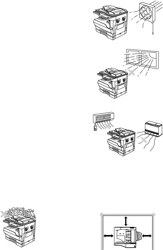
C. Note for installation place
Improper installation may damage the machine. Please note the following during initial installation and whenever the machine is moved.
Caution : If the machine is moved from a cool place to a warm place, condensation may form inside the machine. Operation in this condition will cause poor copy quality and malfunctions. Leave the machine at room temperature for at least 2 hours before use.
Do not install your machine in areas that are:
•damp, humid, or very dusty
•poorly ventilated
•exposed to direct sunlight
•subject to extreme temperature or humidity changes, e.g., near an air conditioner or heater.
The machine should be installed near an accessible power outlet for easy connection and disconnection.
Be sure to connect the power cord only to a power outlet that meets the specified voltage and current requirements. Also make certain the outlet is properly grounded.
Note : Connect the machine to a power outlet which is not used for other electric appliances. If a lighting fixture is connected to the same outlet, the light may flicker.
Be sure to allow the required space around the machine for servicing and proper ventilation.
|
8" (20cm) |
8" |
8" |
(20cm) |
(20cm) |
AR-M205 GENERAL 1-1
[2] SPECIFICATIONS
1. Copy mode
A. Type
Type |
Desk-top |
|
|
Paper exit |
Wing less |
|
|
B. Machine composition
AR-M160 |
16-CPM multi function model |
|
|
AR-M205 |
20-CPM multi function model |
|
|
(1) Option
Machine |
Model |
|
|
|
|
250 sheets paper feed unit |
AR-D24 |
|
|
|
|
250 sheets x 2 paper feed unit |
AR-D25 |
|
|
|
|
SPF |
AR-SP6 |
AR-M160 only |
|
|
|
RSPF |
AR-RP6 |
AR-M205 only |
|
|
|
Original cover |
AR-VR5 |
|
|
|
|
Dual function board |
AR-EB7 |
|
|
|
|
Network expansion kit |
AR-NB2 |
Available from October |
|
|
|
PS3 expansion kit |
AR-PK1/N |
option for AR-NB2 |
|
|
|
256MB optional memory |
AR-SM5 |
|
|
|
|
C. Copy speed
(1) Scan One Print many
AR-M205 / M160 |
Available |
|
|
Condition: Copy speed in the normal copy from all the paper feed ports including the manual paper feed port.
(2) Continuous copy speed (Sheets/min)
a. AR-M160
Paper size |
Normal |
Enlargement |
Reduction |
|||
(200%) |
(50%) |
|||||
|
|
|
|
|||
|
|
|
|
|
|
|
|
|
A3 |
9 |
9 |
9 |
|
|
|
|
|
|
|
|
|
|
B4 |
10 |
10 |
10 |
|
|
|
|
|
|
|
|
AB |
|
A4 |
16 |
16 |
16 |
|
system |
|
|
|
|
|
|
|
A4R |
12 |
12 |
12 |
||
|
|
|
|
|
|
|
|
|
B5 |
16 |
16 |
16 |
|
|
|
|
|
|
|
|
|
|
B5R |
14 |
14 |
14 |
|
|
|
|
|
|
|
|
|
|
11" X 17" |
9 |
9 |
9 |
|
|
|
|
|
|
|
|
|
|
8.5" X 14" |
10 |
10 |
10 |
|
|
|
|
|
|
|
|
Inch |
|
8.5" X 13" |
11 |
11 |
11 |
|
system |
|
|
|
|
|
|
|
8.5" X 11" |
16 |
16 |
16 |
||
|
|
|
|
|
|
|
|
|
8.5" X 11"R |
12 |
12 |
12 |
|
|
|
|
|
|
|
|
|
|
8.5" X 5.5" |
16 |
16 |
16 |
|
|
|
|
|
|
|
|
b. AR-M205 |
|
|
|
|
||
|
|
|
|
|
|
|
Paper size |
Normal |
Enlargement |
Reduction |
|||
(200%) |
(50%) |
|||||
|
|
|
|
|||
|
|
|
|
|
|
|
|
|
A3 |
11 |
11 |
11 |
|
|
|
|
|
|
|
|
|
|
B4 |
12 |
12 |
12 |
|
|
|
|
|
|
|
|
AB |
|
A4 |
20 |
20 |
20 |
|
system |
|
|
|
|
|
|
|
A4R |
14 |
14 |
14 |
||
|
|
|
|
|
|
|
|
|
B5 |
20 |
20 |
20 |
|
|
|
|
|
|
|
|
|
|
B5R |
16 |
16 |
16 |
|
|
|
|
|
|
|
|
|
|
11" X 17" |
10 |
10 |
10 |
|
|
|
|
|
|
|
|
|
|
8.5" X 14" |
12 |
12 |
12 |
|
|
|
|
|
|
|
|
Inch |
|
8.5" X 13" |
12 |
12 |
12 |
|
system |
|
|
|
|
|
|
|
8.5" X 11" |
20 |
20 |
20 |
||
|
|
|
|
|
|
|
|
|
8.5" X 11"R |
15 |
15 |
15 |
|
|
|
|
|
|
|
|
|
|
8.5" X 5.5" |
20 |
20 |
20 |
|
|
|
|
|
|
|
|
D. First copy time
(1) Basic speed
First copy time |
7.2sec (A4, 8.5" X 11"/1st tray/with OC) |
|
(Polygon motor ready state) |
|
|
E. Document
Max. document size |
A3, 11" X 17" |
|
|
Document reference |
Left side center |
position |
|
|
|
Detection (Platen) |
None |
|
|
Detection size |
A3, B4, A4, A4R, B5, B5R, A5 |
|
11" X 17", 8.5" X 14", 8.5" X 13", 8.5" X 11", |
|
8.5" X 11"R, 8.5" X 5.5" |
|
(8.5" X 13" is detected by key input.) |
|
|
(1) SPF/R-SPF
Standard/Option |
Option |
|
SPF: AR-SP6 (AR-M160 only) |
|
RSPF: AR-RP6 (AR-M205 only) |
|
|
Document load |
40 sheets (Thickness 4mm or less) |
capacity |
|
|
|
Document size |
A3 ~ A5 |
(Max. ~ Min.) |
11" x 17" ~ 8.5" x 5.5" |
|
(8.5" x 5.5", duplex is inhibited.) |
|
|
Document |
AR-M205:20 sheets/min |
replacement speed |
AR-M160:16 sheets/min |
|
(A4 , 8.5" x 11" normal copy) |
|
|
Document set/Paper |
Face up, Center reference, |
feed direction |
Paper feed from the top |
|
|
Document weight |
56 ~ 90g/m², 15 ~ 24 lbs |
|
|
Document size |
On the document feed tray |
detection |
|
|
|
Document mixture |
Copy mode: Not Available |
|
|
F. Paper feed
Copy size |
A3 ~ A6 |
|
(Max. ~ Min.) |
11" x 17" ~ 8.5" x 5.5" |
|
|
|
|
Paper feed system |
1 cassette + Multi manual paper feed |
|
|
|
|
Paper feed capacity |
AR-M205 |
250 x 2 (Paper feed tray) |
|
|
+ 100 (Multi bypass feed tray) |
|
|
|
|
AR-M160 |
250 x 1 (Paper feed tray) |
|
|
+ 100 (Multi bypass feed tray) |
|
|
|
Remaining quantity |
Cassette |
Only empty detection available |
detection |
section |
|
|
|
|
|
Manual tray |
Only empty detection available |
|
|
|
(1) Paper feed section of the copier
Paper feed |
A3, B4, A4, A4R, B5, B5R, A5 |
size |
11" x 17", 8.5" x 14", 8.5" x 13", 8.5" x 11", |
|
8.5" x 11"R, 8.5" x 5.5" |
|
(For A5 and 8.5" x 5.5", only No. 1 tray available.) |
|
|
Side front |
Front |
|
|
Paper feed |
250 sheets |
capacity |
(56 ~ 90g/m² equivalent) (15 ~ 21 lbs.) |
|
|
Detection |
Paper empty detection available, size detection |
|
(by key input) |
|
|
Weight |
56 ~ 90g/m² (15 lbs. ~ 21 lbs.) |
|
|
Special paper |
Recycled paper |
|
|
AR-M205 SPECIFICATIONS 2-1
(2) Manual paper feed section
Paper feed |
A3 ~ A6, 11" x 17" ~ 8.5" x 5.5" |
size |
|
|
|
Paper feed |
100 sheets(56 ~ 80g/m²) |
capacity |
|
|
|
Detection |
Size detection not available, |
|
paper empty detection available |
|
|
Weight |
56 ~ 200g/m² (15 ~ 34 lbs.) |
|
|
Special paper |
Recycled paper, OHP film, labels |
|
|
Paper feed |
Single except for recycled paper |
|
|
(3) Option paper feed unit
|
1-step paper feed unit |
2-step paper feed unit |
|
|
|
Model |
AR-D24 |
AR-D25 |
|
|
|
Paper feed size |
A3, B4, A4, A4R, B5, B5R |
|
|
11" x 17", 8.5" x 14", 8.5" x 13", |
|
|
8.5" x 11", 8.5" x 11"R |
|
|
|
|
Capacity |
About 250 sheets x |
About 250 sheets x |
(56 ~ 80gm²) |
1 step |
2 steps |
|
|
|
Paper weight |
56 ~ 90 g/m² (15 ~ 21 |
lbs.) |
|
|
|
Moisture preserving |
None |
|
heater |
|
|
|
|
|
Paper empty detection |
Available |
|
|
|
|
Paper size setting |
User setting |
|
|
Paper size detection:None |
|
|
|
|
External dimensions |
590 x 471 x 88mm |
590 x 471 x 173.5mm |
(W x D x H) |
|
|
|
|
|
Weight |
About 4.7kg |
About 10kg |
|
|
|
Special paper |
Recycled paper |
|
|
|
|
Power |
Supplied from the machine |
|
|
|
|
G. Job speed
S-S (1st step) |
100% (document replacement rate) |
||
|
|
|
|
Condition:With SPF/RSPF A4/Letter Normal 1cassette |
|||
H. Multi copy |
|
|
|
|
|
|
|
Max. number of multi copy |
|
999 sheets |
|
|
|
|
|
I. Warm-up time |
|
|
|
|
|
|
|
Warm-up time |
45 sec |
|
|
|
|
|
|
Pre-heat |
Available |
|
|
|
|
||
Jam recovery |
Within 45 sec |
||
|
|
|
|
J. Copy magnification ratio |
|
||
|
|
|
|
Fixed |
AB system: |
|
|
magnification |
50, 70, 81, 86, 100, 115, 122, 141, 200% |
||
ratio |
|
||
Inch system: |
|||
|
50, 64, 77, 95, 100, 121, 129, 141, 200% |
||
|
|
|
|
Zooming |
25 ~ 400% |
|
|
|
SPF/RSPF(50 ~ 200%) |
||
|
|
||
Independent |
Available (25 ~ 400%) |
||
zooming(vertical) |
SPF/RSPF(50 ~ 200%) |
||
|
|
||
Independent zooming |
Available (25 ~ 400%) |
||
(horizontal) |
SPF/RSPF(50 ~ 200%) |
||
|
|
|
|
K. Print density
Density mode |
Auto / Text / Photo |
|
|
No. of manual |
5 steps (Text / Photo) |
adjustment |
|
|
|
Resolution |
Writing: 600 x 600dpi |
|
Reading: 600 (main) x 600 (sub) (PHOTO mode) |
|
600 (main) x 300 (sub) (AE mode) |
|
|
Gradation |
Reading: 256 gradations |
|
Writing: Binary |
|
|
Toner save mode |
Set by the user program |
|
|
L. Void width
Void area |
Lead edge 1 ~ 4mm, |
|
rear edge 4mm or less, |
|
both sides 4mm or less |
|
|
Image loss |
4mm or less |
|
|
M. Auto duplex
Standard/ |
Standard provision (AR-M205 only) |
Option |
(D → D / D → S enable only when RSPF is installed) |
|
Not available for AR-M160 |
|
|
N. Paper exit / finishing
Paper exit section |
Face down 250 sheets |
capacity |
|
|
|
Full detection |
None |
|
|
Finishing |
Dual function board: |
|
Option (AR-EB7) |
|
|
Electronic sort |
A4 (8.5" x 11") standard document 100 sheets |
capacity |
|
|
|
Offset function |
Available (by the shifter) |
|
|
Staple function |
None |
|
|
(1) Electronic sort board (Option)
Electronic sort |
Sorting |
100 sheets of A4 standard |
|
|
documents |
|
|
|
|
Grouping |
100 sheets of A4 standard |
|
|
documents |
|
|
|
Rotation copy |
If there is paper of same size as the document, |
|
|
the image is rotated to copy even though the |
|
|
paper is set in the different direction from the |
|
|
document direction. |
|
|
|
|
2 in 1, 4 in 1 |
Copies of 2 pages or 4 pages are integrated into |
|
|
one surface. Divided by solid lines, |
|
|
(Selectable by the user program.) |
|
|
|
|
Edge erase |
Images surrounding the document are erased |
|
|
when copying. (Adjustable in 5 ~ 20mm by the |
|
|
user program.) |
|
|
|
|
Center erase |
The image at the center is erased when copying. |
|
|
(Adjustable in 5 ~ 20mm by the user program.) |
|
|
|
|
Margin shift |
Binding margin is made at the left edge of the set |
|
|
documents. |
|
|
(Adjustable in 5 ~ 20mm by the user program.) |
|
|
|
|
Memory for |
16MB |
|
electronic sort |
|
|
|
|
|
* Memory loading |
A4 standard 100 pages |
|
capacity |
|
|
|
|
|
Memory expansion |
DIMM memory slot x 1, max. 256MB x 1 slot + |
|
|
16MB (Max. 272MB in total) |
|
|
|
|
USB2.0 |
Standard provision of E-sort |
|
|
|
|
SPLC (JBIG-GDI) |
Supported when E-sort is installed. |
|
|
|
|
ROPM |
Supported when E-sort is installed. |
|
|
|
|
AR-M205 SPECIFICATIONS 2-2

O. Additional functions
APS |
|
|
O |
|
|
|
|
|
|
|
|
|
|
AMS |
|
|
O |
|
|
|
|
|
|
|
|
|
|
Auto tray switching |
|
O |
|
|
||
|
|
|
|
|
|
|
Memory copy |
|
O |
|
|
||
|
|
|
|
|
|
|
Rotation copy |
|
|
|
|
|
|
|
|
|
|
|
|
|
E-sort |
|
O |
Option |
|||
|
|
|
|
|
|
|
Rotation sort |
|
X |
|
|
||
|
|
|
|
|
|
|
Independent |
|
O |
|
|
||
zooming |
|
|
|
|
|
|
|
|
|
|
|
|
|
1 set 2 copy |
|
O |
Enlargement invalid/SPF invalid (Patent |
|||
|
|
|
|
|
rotation) |
|
|
|
|
|
|
|
|
Binding margin |
|
|
|
Default AB series: |
||
|
|
|
|
|
10mm (5, 10, 15, 20mm) |
|
|
|
|
|
|
Inch series: 1/2 inch (1/4, 1/2, 3/4, 1 inch) |
|
|
|
|
|
|
|
|
Edge erase |
|
|
|
Default AB series: |
||
|
|
|
|
|
10mm (5, 10, 15, 20mm) |
|
|
|
|
|
|
Inch series: 1/2 inch (1/4, 1/2, 3/4, 1 inch) |
|
|
|
|
|
|
|
|
Center erase |
|
|
|
Default AB series: |
||
|
|
|
|
|
10mm (5, 10, 15, 20mm) |
|
|
|
|
|
|
Inch series: 1/2 inch (1/4, 1/2, 3/4, 1 inch) |
|
|
|
|
|
|
|
|
Black/white |
|
X |
|
|
||
reverse |
|
|
|
|
|
|
|
|
|
|
|
|
|
2in1/4in1 |
|
|
|
|
|
|
|
|
|
|
|
|
|
Sorter |
|
O |
Offset function (Shifter) provided |
|||
|
|
|
|
|
|
|
Preheating |
|
O |
The conditions are set by the user |
|||
|
|
|
|
|
program. |
|
|
|
|
|
|
|
|
Auto shut-off |
|
O |
The conditions are set by the user |
|||
|
|
|
|
|
program. |
|
|
|
|
|
|
|
|
User programming |
|
O |
|
|
||
|
|
|
|
|
|
|
Total counter |
|
O |
Supports Total counter, Scan counter, and |
|||
|
|
|
|
|
Copy counter. |
|
|
|
|
|
|
|
|
Coin vendor |
|
O |
(Supports I/F only.) |
|||
support |
|
|
|
|
|
|
|
|
|
|
|
|
|
Auditor support |
|
O |
(Supports I/F only.) |
|||
|
|
|
|
|
|
|
Duplex |
|
O |
(Standard provision for the model of 20- |
|||
|
|
|
|
|
sheet model only) |
|
|
|
|
|
|
|
|
Toner save |
|
O |
(Set according to the destination) |
|||
|
|
|
|
|
|
|
Department |
|
O |
(Copy: 20 Dept.) |
|||
management |
|
|
|
|
|
|
|
|
|
|
|
|
|
O |
: Available |
|
|
|
:Installation of the option is required. |
|
X |
: Not available |
|
|
|
|
|
P. Other specifications |
||||||
|
|
|
|
|
||
Photoconductor type |
|
|
|
OPC (Organic Photo Conductor) |
||
|
|
|
|
|||
Photoconductor drum dia. |
|
30mm |
||||
|
|
|
|
|
||
Copy lamp |
|
|
|
Cold cathode fluorescent lamp (CCFL) |
||
|
|
|
|
|
||
Developing system |
|
|
|
Dry 2-component magnetic brush |
||
|
|
|
|
|
|
development |
|
|
|
|
|
||
Charging system |
|
|
|
Saw teeth charging |
||
|
|
|
|
|
||
Transfer system |
|
|
|
(+) DC corotron |
||
|
|
|
|
|
||
Separation system |
|
|
|
(-) DC corotron |
||
|
|
|
|
|
||
Fusing system |
|
|
|
Heat roller |
||
|
|
|
|
|
||
Cleaning system |
|
|
|
Contact blade |
||
|
|
|
|
|
||
Q. Package form |
|
|
|
|
||
|
|
|
|
|
||
Body |
|
|
|
Body / Accessories |
||
|
|
|
|
|
|
|
R. External view
External dimensions |
590 x 577 x 520 mm(AR-M205) |
(W x D x H) |
590 x 577 x 470 mm(AR-M160) |
|
|
Occupying area |
590 x 531mm |
(W x D) |
(When the manual tray is installed.) |
|
|
Weight |
About 31.3kg (AR-M160) |
|
About 35.1kg (AR-M205) |
|
|
S. Power source
Voltage |
AC120V, 220V, 230V, 240V ±15% |
|
|
Frequency |
50/60Hz common |
|
|
T. Power consumption
Max. power consumption |
|
1200W |
|||
* EnergyStar conformity |
|
|
|||
|
|
|
|
|
|
Average power consumption in |
|
Less than 550W |
|||
operation |
|
|
|
|
|
Power consumption when |
|
5W(Not include option) |
|||
standby |
|
|
|
|
|
Energy consumption efficiency |
|
Less than 25W |
|||
U. Digital performance |
|
|
|||
|
|
|
|
||
Resolution |
|
Reading |
600 x 600dpi (PHOTO mode) |
||
|
|
|
|
|
600 x 300dpi (AE mode) |
|
|
|
|
|
|
|
|
Writing |
|
600 x 600dpi |
|
|
|
|
|
||
Gradation |
|
Reading |
256 gradations |
||
|
|
|
|
|
|
|
|
Writing |
|
Binary |
|
|
|
|
|
||
Memory |
|
Simplex:16MB |
Duplex:32MB |
||
|
|
|
|
|
|
Hard disk |
|
None |
|
|
|
|
|
|
|
|
|
V. Printing function |
|
|
|||
|
|
||||
Print speed |
<Standard>12ppm |
||||
|
(With the AR-EB7 installed) |
||||
|
16ppm (AR-M160) / 20ppm (AR-M205) |
||||
Data resolution |
600dpi |
|
|
||
Option memory |
16MB (with the AR-EB7 installed) |
||||
|
256MB (AR-SM5) can be added to the AR-EB7. |
||||
Printer driver |
Two drivers for the case when the AR-EB7 is |
||||
|
installed and when it is not are automatically |
||||
|
installed by plug & play. |
||||
|
<Standard> SHARP GDI driver |
||||
|
<with the AR-EB7 installed> SPLC driver |
||||
W. Scanner function |
|
|
|||
|
|
|
|||
Type |
|
Flat bed color scanner |
|||
Scan system |
|
Document table/document feed unit |
|||
Light source |
|
White CCFL |
|
||
Resolution |
|
Basic 600 x 1200dpi |
|||
|
|
Set range: 50 ~ 9600dpi |
|||
Document |
|
Sheet/Book |
|
||
Effective scan range |
|
OC/SPF: about 297(length) x 431(width) mm |
|||
Scan speed |
|
OC/SPF: 2.88msec/line (Color) |
|||
Input data |
|
1bit or 12bit |
|
||
Output data |
|
1bit or 8bit |
|
||
Scan color |
|
Black and white binaryGray scaleFull color |
|||
Protocol |
|
TWAIN/WIA (XP only) / STI |
|||
Interface |
|
USB1.1 |
|
|
|
|
|
USB2.0 |
|
|
|
|
|
(Option support: High-speed mode/Full speed |
|||
|
|
mode (Switched by the user program.)) |
|||
|
|
(Supported when E-sort is installed) |
|||
Scanner utility |
|
Sharp Desk/Button Manager |
|||
Drop-out color |
|
Provided |
|
||
Scanner button |
|
Provided (6) |
|
||
Supported OS |
|
Windows98/ME/2000/XP |
|||
Void area |
|
Lead edge/rear edge (2.5mm) on the driver |
|||
|
|
side Left/right: 3.0mm |
|||
WHQL support |
|
Yes |
|
|
|
AR-M205 SPECIFICATIONS 2-3
[3] CONSUMABLE PARTS
1.Supply system table
A.USA/CANADA/Latin America
NO |
Name |
Content |
|
Life |
Product name |
Remark |
|
|
|
|
|
|
|
1 |
Toner cartridge(Black) |
Toner |
x10 |
160K |
AR-202MT |
Life setting by A4 6% document |
|
<With IC> |
(Toner: Net Weight 537g) |
|
|
|
|
|
|
Vinyl bag |
x10 |
|
|
|
|
|
|
|
|
|
|
2 |
Developer |
Developer |
x10 |
500K |
AR-202MD |
|
|
|
(Developer : Net Weight 400g) |
|
|
|
|
|
|
|
|
|
|
|
3 |
Drum kit |
Drum |
x1 |
50K |
AR-202DR |
|
|
|
Drum fixing plate |
x1 |
|
|
|
|
|
|
|
|
|
|
B. Middle East/Africa/Taiwan/Philippine
NO |
Name |
Content |
|
Life |
Product name |
Remark |
|
|
|
|
|
|
|
1 |
Toner cartridge(Black) |
Toner |
x10 |
160K |
AR-202ET |
Life setting by A4 6% document |
|
<With IC> |
(Toner: Net Weight 537g) |
|
|
|
|
|
|
Vinyl bag |
x10 |
|
|
|
|
|
|
|
|
|
|
2 |
Developer |
Developer |
x10 |
500K |
AR-202CD |
|
|
|
(Developer : Net Weight 400g) |
|
|
|
|
|
|
|
|
|
|
|
3 |
Drum kit |
Drum |
x1 |
50K |
AR-202DR |
|
|
|
Drum fixing plate |
x1 |
|
|
|
|
|
|
|
|
|
|
C. Europe/East Europe
NO |
Name |
Content |
|
Life |
Product name |
Remark |
|
|
|
|
|
|
|
1 |
Toner cartridge(Black) |
Toner |
x10 |
160K |
AR-202LT |
Life setting by A4 6% document |
|
<With IC> |
(Toner: Net Weight 537g) |
|
|
|
|
|
|
Vinyl bag |
x10 |
|
|
|
|
|
|
|
|
|
|
2 |
Developer |
Developer |
x10 |
500K |
AR-202LD |
|
|
|
(Developer : Net Weight 400g) |
|
|
|
|
|
|
|
|
|
|
|
3 |
Drum kit |
Drum |
x1 |
50K |
AR-202DM |
|
|
|
Drum fixing plate |
x1 |
|
|
|
|
|
|
|
|
|
|
D. Asia
NO |
Name |
Content |
|
Life |
Product name |
Remark |
|
|
|
|
|
|
|
1 |
Toner cartridge(Black) |
Toner |
x10 |
160K |
AR-202CT |
Life setting by A4 6% document |
|
<With IC> |
(Toner: Net Weight 537g) |
|
|
|
|
|
|
Vinyl bag |
x10 |
|
|
|
|
|
|
|
|
|
|
2 |
Developer |
Developer |
x10 |
500K |
AR-202CD |
|
|
|
(Developer : Net Weight 400g) |
|
|
|
|
|
|
|
|
|
|
|
3 |
Drum kit |
Drum |
x1 |
50K |
AR-202DR |
|
|
|
Drum fixing plate |
x1 |
|
|
|
|
|
|
|
|
|
|
E.Hong Kong/China
NO |
Name |
Content |
|
Life |
Product name |
Remark |
|
|
|
|
|
|
|
|
|
1 |
Toner cartridge(Black) |
Toner |
x10 |
160K |
AR-202CT-C |
Life setting by |
A4 6% document |
|
<With IC> |
(Toner: Net Weight 645g) |
|
|
|
|
|
|
(Hong Kong only) |
Vinyl bag |
x10 |
|
|
|
|
|
|
|
|
|
|
|
|
2 |
Toner cartridge(Black) |
Toner |
x1 |
19K |
AR-203ST-C |
Life setting by |
A4 6% document |
|
<With IC> |
(Toner: Net Weight 645g) |
|
|
|
|
|
|
(China only) |
Vinyl bag |
x1 |
|
|
|
|
|
|
|
|
|
|
|
|
3 |
Developer |
Developer |
x10 |
500K |
AR-202CD-C |
|
|
|
|
(Developer : Net Weight 4500) |
|
|
|
|
|
|
|
|
|
|
|
|
|
4 |
Drum kit |
Drum |
x1 |
50K |
AR-202DR-C |
|
|
|
|
Drum fixing plate |
x1 |
|
|
|
|
|
|
|
|
|
|
|
|
AR-M205 CONSUMABLE PARTS 3-1
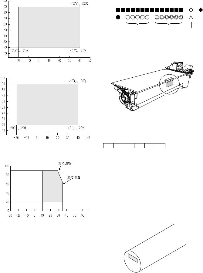
2. Environmental conditions
A. Transport conditions
(1) Transport conditions
Humidity (%) |
Temperature 

(2) Storage conditions
Humidity (%) |
Temperature 

3. Production number identification
<Toner cartridge>
The label on the toner cartridge shows the date of production.
Production |
Serial |
Year/ |
Ver.No. |
place |
number |
Month/ |
|
|
|
Day |
|
<Drum cartridge>
The lot number, printed on the front side flange, is composed of 6 digits, each digit showing the following content:
1 |
2 |
3 |
4 |
5 |
6 |
B. Use conditions
1Alphabet
Indicates the model conformity code. A for this model.
|
|
2 |
Number |
|
|
|
Indicates the end digit of the production year. |
(%) |
|
3 |
Number or X, Y, Z |
Use envi- |
|
Indicates the month of packing. |
|
Humidity |
ronment |
|
Indicates the day of the month of packing. |
|
|
X stands for October, Y November, and Z December. |
|
|
conditions |
4/5 |
Number |
|
|
6 |
Alphabet |
|
|
|
Indicates the production factory. "A" for Nara Plant, “C“ for |
|
|
|
SOCC |
Temperature 

C. Life(packed conditions)
Photoconductor drum (36 months from the production month)
Developer, toner (24 months from the production month)
AR-M205 CONSUMABLE PARTS 3-2
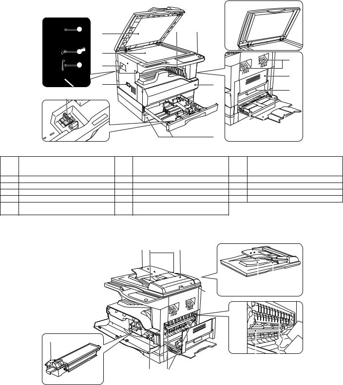
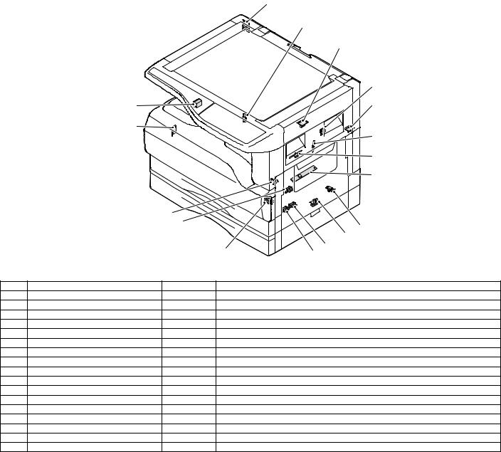
[4] EXTERNAL VIEWS AND INTERNAL STRUCTURES
1. Appearance
17 |
6 |
5 |
|
1 |
|
15 |
2 |
|
16 |
3 |
|
|
4 |
7 |
14 |
1
3 |
9 |
10
|
|
|
|
|
8 |
|
11 |
12 |
13 |
1 |
Document feeder cover (when the SPF/ |
2 |
Document glass |
|
3 |
Handles |
|
||
|
RSPF is installed) /document cover |
|
|
|
|
|
|
|
|
|
(when the document cover is installed) |
|
|
|
|
|
|
|
|
4 |
Power switch |
5 |
Operation panel |
|
6 |
Paper output tray |
|||
7 |
Front cover |
8 |
Paper trays |
|
9 |
Side cover |
|
||
10 |
Side cover handle |
11 |
Bypass tray guides |
|
12 |
Bypass tray |
|
||
13 |
Bypass tray extension |
14 |
Charger cleaner |
|
15 |
USB 1.1 port |
|
||
16 |
Parallel port |
17 |
USB 2.0 port (when the dual function |
|
|
|
|
||
|
|
|
board is installed) |
|
|
|
|
|
|
2. Internal |
|
|
|
|
|
|
|
|
|
|
|
|
18 |
19 |
20 |
|
|
|
|
21 |
22 |
23 |
24 |
26 |
27 |
28 |
29 |
25
18 |
Document feeder tray |
19 |
Original guides |
20 |
Feeding roller cover |
|
(when the SPF/RSPF is installed) |
|
(when the SPF/RSPF is installed) |
|
(when the SPF/RSPF is installed) |
21 |
Right side cover |
22 |
Exit area |
23 |
Reversing tray |
|
(when the SPF/RSPF is installed) |
|
(when the SPF/RSPF is installed) |
|
(when the RSPF is installed) |
24 |
Toner cartridge lock release lever |
25 |
Toner cartridge |
26 |
Roller rotating knob |
27 |
Fusing unit release levers |
28 |
Photoconductive drum |
29 |
Fusing unit paper guide |
AR-M205 EXTERNAL VIEWS AND INTERNAL STRUCTURES 4-1
3. Operation Section
|
|
|
1 |
|
|
2 |
3 |
4 |
5 |
6 |
|
|
|
|
|
|
SCAN |
ON LINE |
ORIGINAL TO COPY |
XY- |
|
1 |
1 |
2 |
3 |
4 |
5 |
6 |
|
|
|
ZOOM |
|
|
|
|
|||||||
2 |
|
|
|
|
|
|
|
|
|
|
|
|
|
|
|
|
|
|
|
|
DUAL |
|
|
|
|
|
|
|
|
|
|
PAGE |
|
|
|
|
|
|
|
|
|
|
COPY |
The AR-M160 is shown below.
ON LINE |
XY- |
|
ZOOM |
DUAL
PAGE
COPY
PAPER
SIZE
X17
X14
X11

X5½ 
X11
TRA
E |
TRAY |
AUTO |
20
14
12
12
10
9
7
6
5
1 |
|
SCAN MENU key |
|
|
|
|
|
2 |
|
SCAN key/indicator |
|
|
|
3 |
|
ON LINE key/indicator |
|||||
4 |
|
ORIGINAL TO COPY key/indicators |
|
|
5 |
|
DUAL PAGE COPY key/indicator |
|
6 |
|
XY-ZOOM key/indicator |
||||||||||
|
|
|
(AR-M205 only) |
|
|
|
|
|
|
|
|
|
|
|
|
|
|
|
|
|
|
|
|
7 |
8 |
9 |
10 11 12 |
13 |
|
14 |
15 |
16 |
17 |
18 |
19 |
20 |
21 |
|
|||||
ORIGINAL DATA |
AUDIT CLEAR |
AUTO PAPER SELECT |
POWER SAVE |
|||||
|
|
|
|
|
|
|
||
SORT |
|
|
|
|
|
|
|
|
GROUP |
2 IN 1 |
|
|
|
ORIGINAL |
PAPER |
|
200% |
|
|
AUTO |
|
|||||
|
4 IN 1 |
|
SIZE |
SIZE |
|
141 |
||
|
|
TEXT |
11X17 |
|
||||
|
|
|
PHOTO |
8½X14 |
|
129 |
||
EDGE |
|
|
|
|
8½X11 |
|
121 |
|
|
|
|
|
|
100% |
|||
ERASE |
|
|
|
|
8½X5½ |
|
||
|
|
|
|
|
95 |
|||
CENTER |
|
|
|
|
8½X11 |
|
||
MARGIN |
|
|
|
|
77 |
|||
|
|
|
|
EXTRA |
|
64 |
||
|
SHIFT |
1 |
3 |
5 |
|
|||
|
|
|
|
|||||
|
|
|
|
|
50% |
|||
|
|
|
|
|
ORIGINAL SIZE |
TRAY |
AUTO |
PRESET RATIO |
|
|
|
|
|
ENTER |
SELECT |
IMAGE |
|
ZOOM |
25 |
400% |
INTERRUPT |
CLEAR
CLEAR ALL
START
READ-END
|
22 |
23 |
24 25 26 27 |
28 |
29 |
30 |
31 |
32 |
33 |
34 |
35 |
36 |
|
|
|
||||||||||
|
|
|
|
|
|
|
|
|
|
|
|
|
|
|
|
|
|
|
|||||||
7 |
SORT/GROUP key/indicators |
8 |
ORIGINAL DATA indicator |
|
|
9 |
2 IN 1 / 4 IN 1 key/indicators |
||||||||||||||||||
|
(when the dual function board is |
|
(when the dual function board is |
|
|
|
(when the dual function board is |
||||||||||||||||||
|
installed) |
|
installed) |
|
|
|
|
|
|
|
|
|
installed) |
|
|
|
|
|
|
||||||
10 |
ERASE key/indicators |
11 |
MARGIN SHIFT key/indicator |
|
|
12 |
AUTO/TEXT/PHOTO key / indicators |
||||||||||||||||||
|
(when the dual function board is |
|
(when the dual function board is |
|
|
|
|
|
|
|
|
|
|
|
|||||||||||
|
installed) |
|
installed) |
|
|
|
|
|
|
|
|
|
|
|
|
|
|
|
|
|
|||||
13 |
AUDIT CLEAR key |
14 |
AUTO PAPER SELECT indicator |
|
|
15 |
Alarm indicators |
|
|
||||||||||||||||
16 |
POWER SAVE indicator |
17 |
Display |
|
|
|
|
|
|
|
|
18 |
Copy ratio display key ( |
) |
|||||||||||
19 |
ZOOM indicator |
20 |
Zoom keys ( |
|
, |
|
|
) |
|
|
|
|
21 |
INTERRUPT key ( |
) / indicator |
||||||||||
22 |
Light and Dark keys ( , ) / indicators |
23 |
ORIGINAL SIZE ENTER key / |
|
|
24 |
PAPER SIZE indicators |
|
|||||||||||||||||
|
|
|
|
|
|
|
ORIGINAL SIZE indicators |
|
|
|
|
|
|
|
|
|
|
|
|||||||
25 |
PAPER SIZE ENTER key |
26 |
SPR/RSPF indicator |
|
|
|
27 |
TRAY SELECT key ( |
) |
||||||||||||||||
|
|
|
|
|
|
|
(when the SPF/RSPF is installed) |
|
|
|
|
|
|
|
|
|
|
|
|||||||
28 |
AUTO IMAGE key/indicator |
29 |
Paper feed location/misfeed location |
|
30 |
PRESET RATIO selector keys ( , ) / |
|||||||||||||||||||
|
|
|
|
|
|
|
indicators |
|
|
|
|
|
|
|
|
|
indicators |
|
|
|
|
|
|
||
31 |
[ |
|
] key |
32 |
Numeric keys |
|
|
|
|
|
|
|
|
33 |
READ-END key ( |
|
) |
|
|||||||
34 |
START key ( |
|
) /indicators |
35 |
CLEAR ALL key ( |
|
|
) |
|
|
|
36 |
CLEAR key ( |
|
) |
|
|
|
|||||||
AR-M205 EXTERNAL VIEWS AND INTERNAL STRUCTURES 4-2
4. Motor, solenoid, clutch
|
1 |
|
2 |
|
3 |
|
4 |
|
5 |
18 |
6 |
7 |
|
|
8 |
|
9 |
|
10 |
|
11 |
|
12 |
|
13 |
|
|
|
14 |
|
|
|
15 |
|
|
|
17 16 |
|
|
|
|
No. |
Name |
Code |
Function operation |
|
|
|
|
1 |
Mirror motor |
MRM |
Drives the optical mirror base (scanner unit). |
|
|
|
|
2 |
Shifter motor |
SHTM |
Shifts the paper exit tray. |
|
|
|
|
3 |
Toner motor |
TM |
Toner supply |
|
|
|
|
4 |
Duplex motor |
DPX |
Switchback operation and paper exit motor in duplex. |
|
|
|
|
5 |
Cooling fan motor |
CFM |
Cools the inside of the machine. |
|
|
|
|
6 |
Main motor |
MM |
Drives the machine. |
|
|
|
|
7 |
1st tray paper feed clutch |
CPFC1 |
Drive the pick up roller |
|
|
|
|
8 |
PS clutch |
RRC |
Drives the resist roller |
|
|
|
|
9 |
Paper feed solenoid |
CPSOL1 |
Solenoid for paper feed from cassette |
|
|
|
|
10 |
Resist roller solenoid |
RRS |
Resist roller rotation control solenoid |
|
|
|
|
11 |
Manual paper transport clutch |
MPTC |
Drives the manual paper transport roller. |
|
|
|
|
12 |
Manual paper feed clutch |
MPFC |
Drives the manual paper feed roller. |
|
|
|
|
13 |
Manual paper feed solenoid |
MPFS |
Manual paper feed solenoid |
|
|
|
|
14 |
2nd tray transport clutch |
CPFC2 |
Drives the 2nd tray transport roller. |
|
|
|
|
15 |
2nd tray transport solenoid |
FSOL1 |
2nd tray transport solenoid |
|
|
|
|
16 |
2nd tray paper feed clutch |
CPFC1 |
Drives the 2nd tray paper feed roller. |
|
|
|
|
17 |
2nd tray paper feed solenoid |
PSOL2 |
2nd tray transport solenoid |
|
|
|
|
18 |
Exhaust fan motor |
VFM |
Cools the inside of the machine. |
|
|
|
|
AR-M205 EXTERNAL VIEWS AND INTERNAL STRUCTURES 4-3
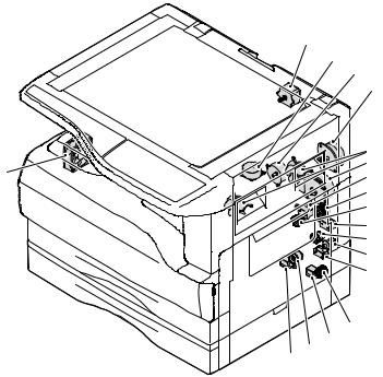
5. Sensor, switch
|
1 |
|
2 |
|
3 |
|
4 |
17 |
5 |
|
|
16 |
6 |
|
|
|
7 |
|
8 |
15
|
|
14 |
|
|
9 |
|
|
|
|
|
|
|
|
|
|
|
10 |
|
|
|
13 |
12 |
11 |
|
|
|
|
||
|
|
|
|
|
|
No. |
Name |
Code |
|
|
Function operation |
1 |
Mirror home position sensor |
MHPS |
Detects the mirror (scanner unit) home position. |
||
2 |
Side door switch |
DSWR |
Side door open detection |
|
|
3 |
Paper exit sensor (paper exit side) |
POD1 |
Detects paper exit. |
|
|
4 |
Shifter home position sensor |
SFTHP |
Shifter home position detection |
|
|
5 |
Paper exit sensor (DUP side) |
PDPX |
Paper transport detection |
|
|
6 |
Thermistor |
RTH |
Fusing section temperature detection |
||
7 |
Thermostat |
|
Fusing section abnormally high temperature detection |
||
8 |
Toner density sensor |
TCS |
Toner quantity detection |
|
|
9 |
2nd tray detection switch |
|
2nd tray detection |
|
|
10 |
Manual sensor |
MPED |
Manual transport detection |
|
|
11 |
2nd tray door open/close sensor |
DRS2 |
2nd tray door open/close detection |
||
12 |
2nd tray door paper pass sensor |
PPD2 |
2nd tray paper entry detection |
|
|
13 |
2nd tray paper empty sensor |
CSS2 |
2nd tray paper empty detection |
|
|
14 |
Paper in sensor |
PIN |
Paper transport detection |
|
|
15 |
Cassette empty |
|
Tray paper entry detection |
|
|
16 |
Front cover SW |
|
Front cover open detection |
|
|
17 |
Power switch |
MAIN SW |
Turns ON/OFF the main power source. |
||
AR-M205 EXTERNAL VIEWS AND INTERNAL STRUCTURES 4-4
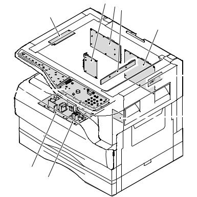
6. PWB unit
2 6 3
1
4

 5 10
5 10 
 7
7
9
8
No. |
Name |
Function operation |
1 |
Copy lamp Inverter PWB |
Copy lamp control |
2 |
I / F PWB |
USB1.1, IEEE1284 I/F |
3 |
CCD sensor PWB |
Image scanning |
4 |
Main control PWB |
Main control PWB |
5 |
Tray PWB |
Shifter motor control |
6 |
IMC2 PWB |
Electronic sort, USB2.0 << Option:AR-EB7>> |
7 |
2nd cassette PWB |
2nd cassette control |
8 |
High voltage PWB |
High voltage control |
9 |
Power PWB |
AC power input/DC power control |
10 |
Operation main PWB |
Operation panel input/Display, operation panel section control |
AR-M205 EXTERNAL VIEWS AND INTERNAL STRUCTURES 4-5
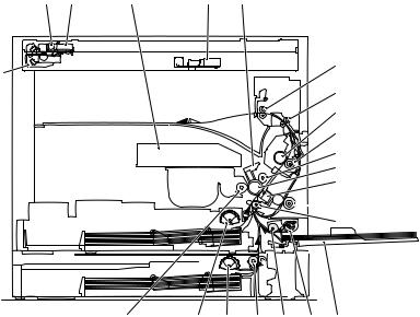
7. Cross sectional view
1 |
2 |
3 |
4 |
5 |
6
18
7 8
9
10
11
12


 13
13
 14 15
14 15
|
23 |
22 |
21 |
20 |
19 |
17 |
16 |
|
|
|
|
|
|
|
|
No. |
Name |
|
|
|
|
Function/Operation |
|
1 |
Copy lamp |
Image radiation lamp |
|
|
|
||
2 |
Copy lamp unit |
Operates in synchronization with No. 2/3 mirror unit to radiate documents |
|||||
|
|
sequentially. |
|
|
|
|
|
3 |
LSU unit |
Converts image signals into laser beams to write on the drum. |
|||||
4 |
Lens unit |
Reads images with the lens and the CCD. |
|||||
5 |
MC holder unit |
Supplies negative charges evenly on the drum. |
|||||
6 |
Paper exit roller |
Used to discharge paper. |
|
|
|||
7 |
Transport roller |
Used to transport paper. |
|
|
|
||
8 |
Upper heat roller |
Fuses toner on paper (with the teflon roller). |
|||||
9 |
Lower heat roller |
Fuses toner on paper (with the silicon rubber roller). |
|||||
10 |
Waste toner transport roller |
Transports waste toner to the waste toner box. |
|||||
11 |
Drum unit |
Forms images. |
|
|
|
|
|
12 |
Transfer charger unit |
Transfer images (on the drum) onto paper. |
|||||
13 |
DUP follower roller |
|
|
|
|
|
|
14 |
Duplex transport roller |
Transports paper for duplex . |
|
|
|||
15 |
Resist roller |
Takes synchronization between the paper lead edge and the image lead edge. |
|||||
16 |
Manual paper feed tray |
Manual paper feed tray |
|
|
|
||
17 |
Manual paper pick up roller |
Picks up paper in manual paper feed. |
|||||
18 |
No. 2/3 mirror unit |
Reflects the images from the copy lamp unit to the lens unit. |
|||||
19 |
Manual transport roller |
Transports paper from the manual paper feed port. |
|||||
20 |
2nd tray paper transport roller |
Transports paper from the 2nd tray. |
|||||
21 |
2nd tray paper pick up roller |
Picks up paper from the 2nd tray. |
|
||||
|
(semi-circular roller) |
|
|
|
|
|
|
22 |
1st tray paper feed roller |
Picks up paper from the 1st tray. |
|
||||
|
(semi-circular roller) |
|
|
|
|
|
|
23 |
MG roller |
Puts toner on the OPC drum. |
|
|
|||
AR-M205 EXTERNAL VIEWS AND INTERNAL STRUCTURES 4-6
[5]UNPACKING AND INSTALLATION
1.Installing conditions
A.Copier installation
Do not install your copier in areas that are: •damp, humid, or very dusty
•exposed to direct sunlight •poorly ventilated
•subject to extreme temperature or humidity changes, e.g., near an air conditioner or heater.
•Be sure to allow the required space around the machine for servicing and proper ventilation.
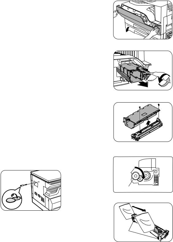
2) Open the front cover.
•Hold the both sides and pull down to open.
3) Loosen the screw and remove the developer cartridge.
B.Power source
•Use an exclusive-use power outlet. If the power plug of this machine is inserted into a power outlet commonly used with other illumination units, flickers of the lamp may be result. Use a power outlet which is not used commonly with any illumination units.
•Avoid complex wiring.
C.Grounding wire connection.
•To avoid danger, be sure to connect a grounding wire. If no grounding wire is connected and a leakage occurs, a fire or an electric shock may be result.
2.Removal of protective material and fixing screw
1) Remove all tapes and protective material.
•Remove all tapes, then open the document cover and remove the protective material of sheet shape
2) Remove the fixing screw.
•Use a coin to remove the fixing screw.
•The fixing screw is required when transporting the machine. Keep it in the tray. (Refer to the later description.)
4) Remove the developer tank from the developer cartridge.
5)Supply developer into the developer tank while rotating the MG roller in the arrow direction.
MG roller
* Shake the developer bag enough before opening it.
3.Installing procedure
Hook
A.Developer cartridge installation
1) Open the manual tray, and open the side cover.
Note:Check that the DV seal is free from developing agent. If developing agent is attached to the DV seal, clean it carefully.
Check to insure that the hook is engaged in two positions.
6) Attach the developer tank to the developer cartridge.
* After supplying developer into the developer cartridge, do not tilt or shake the developer cartridge.
7) Attach the developer cartridge to the copier, and fix it with the screw.
AR-M205 UNPACKING AND INSTALLATION 5-1
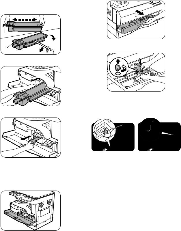
B.Toner cartridge installation
1)Shake the toner cartridge several times horizontally, and remove the tape.
*Do not hold the shutter lever when shaking.
*After removing the tape, do not tilt or shake the toner cartridge.
4 or 5 times
Shutter
 Tape
Tape
Handle 
2) Attach the toner cartridge to the copier.
3) Pull the shutter lever.
Close the front cover A, then close the side cover B. •When closing the front cover, gently press the both sides. •When closing the side cover, hold the knob.
•When closing the covers, be sure to close the front cover first, then close the side cover. If closed in a wrong sequence, the covers may be broken.
4.Removal and storage of fixing screw
1) Lift the knob and gently pull out the tray.
2)Hold the paper pressure plate and turn the fixing screw in the arrow direction.
3) Store the fixing pin and the fixing screw in the tray.
•Store the fixing screw which was removed in the above procedure 2 and the fixing screw which was removed in procedure 2 of 2.
•Removal of protective material and fixing screw in the storage place in the tray.
Pressure  Screw plate
lock
AR-M205 UNPACKING AND INSTALLATION 5-2
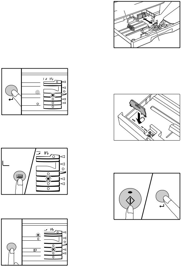
5. Changing the copy paper size in the tray
Note
•The paper size setting cannot be changed when the machine has stopped temporarily due to running out of paper or a misfeed, or during interrupt copying.
•During printing (even in copy mode), the paper size setting cannot be changed.
•5-1/2" x 8-1/2" size paper can only be selected in upper paper tray.
•Do not load paper that is a different size than the paper size setting. Copying will not be possible.
1)Hold down the [PAPER SIZE ENTER] key for more than 5 seconds to set the selected paper size.
The currently selected paper feed location indicator will blink and the corresponding paper size (which is currently set) indicator will light steadily.
All other indicators will go out.
INAL PAPER SIZE 11X17 
8½X14  8½X11
8½X11
 8½X5½
8½X5½  8½X11
8½X11 EXTRA
EXTRA
2)Use the [TRAY SELECT] key to select the paper tray for which you wish to change the paper size setting.
Each time the [TRAY SELECT] key is pressed, a paper tray will be indicated with a blinking paper feed location indicator.
TRAY
SELECT
4)Squeeze the lock lever of the front guide and slide the front guide to match the width of the paper, and move the left guide to the appropriate slot as marked on the tray.
Left guide
Front guide
•The front guide is a slide-type guide. Grasp the locking knob on the guide and slide the guide to the indicator line of the paper to be loaded. •The left guide is an insert-type guide. Remove it and then insert it at the indicator line of the paper to be loaded.
•When using 11" x 17" sized paper store the left guide in the slot at the left front of the paper tray.
6)Press the [START] key and then the [PAPER SIZE ENTER] key.
To change the paper size setting of another tray, repeat steps 2 to 3 after pressing the [START] key.
3)Use the [ORIGINAL SIZE ENTER] key to select the paper size. The indicator of the selected paper size lights up.
GINAL PAPER
SIZE
ORIGINAL SIZE |
11X17 |
8½X14 |
ENTER 8½X11
 8½X5½
8½X5½  8½X11
8½X11  EXTRA
EXTRA 
START
Note
Affix the paper size label for the paper size selected in step 3 to the label position on the right end of the tray.
AR-M205 UNPACKING AND INSTALLATION 5-3
[6]ADJUSTMENTS
1.Adjustment item list
|
Section |
|
Adjustment item |
Adjustment procedure/SIM No. |
|
|
|
|
|
A |
Process |
(1) |
Developing doctor gap adjustment |
Developing doctor gap adjustment |
|
section |
|
|
|
|
(2) |
MG roller main pole position adjustment |
MG roller main pole position adjustment |
|
|
|
|
|
|
|
|
(3) |
Developing bias voltage check |
|
|
|
|
|
|
|
|
(4) |
Main charger voltage check |
|
|
|
|
|
|
B |
Mechanism |
(1) |
Image position adjustment |
SIM-50 |
|
section |
|
|
|
|
(2) |
Main scanning direction (FR direction) distortion balance |
No. 2/3 mirror base unit installing position adjustment |
|
|
|
|
adjustment |
|
|
|
|
Copy lamp unit installing position adjustment |
|
|
|
|
|
|
|
|
(3) |
Main scanning direction (FR direction) distortion adjustment |
Rail height adjustment |
|
|
|
|
|
|
|
(4) |
Sub scanning direction (scanning direction) distortion |
Winding pulley position adjustment |
|
|
|
adjustment |
|
|
|
|
|
|
|
|
(5) |
Main scanning direction (FR direction) magnification ratio |
SIM 48-1 |
|
|
|
adjustment |
|
|
|
|
|
|
|
|
(6) |
Sub scanning direction (scanning direction) magnification ratio |
OC mode in copying (SIM 48-1) |
|
|
|
adjustment |
|
|
|
|
SPF mode in copying (SIM 48-5) |
|
|
|
|
|
|
|
|
(7) |
Off center adjustment |
OC mode (SIM 50-12) |
|
|
|
|
|
|
|
|
|
SPF mode (SIM 50-12) |
|
|
|
|
|
|
|
(8) |
SPF white correction pixel position adjustment |
SIM63-7 |
|
|
|
(required in an SPF model when replacing the lens unit) |
|
|
|
|
|
|
C |
Image density |
(1) |
Copy mode |
SIM 46-1 |
|
adjustment |
|
|
|
|
|
|
|
|
2.Copier adjustment
A.Process section
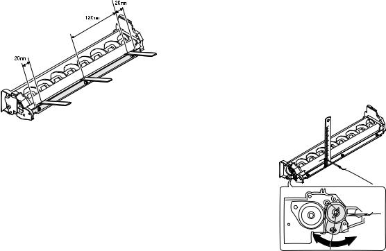
(1) Developing doctor gap adjustment
1)Loosen the developing doctor fixing screw A.
2)Insert a thickness gauge of 1.5mm to the three positions at 20mm and 130mm from the both ends of the developing doctor as shown.
3)Push the developing doctor in the arrow direction, and tighten the developing doctor fixing screw. (Perform the same procedure for the front and the rear frames.)
4)Check the clearance of the developing doctor. If it is within the specified range, then fix the doctor fixing screw with screw lock.
*When inserting a thickness gauge, be careful not to scratch the developing doctor and the MG roller.
<Adjustment specification>
Developing doctor gap
Both ends (20mm from the both ends) : 1.5 +0.1- 0.15 mm
C (Center) (150mm from the both ends) :1.55 +0.15- 0.2 mm
(2) MG roller main pole position adjustment
1)Remove and separate the waste toner box and put the developing unit on a flat surface.
2)Tie a string to a needle or a pin.
3)Hold the string and bring the needle close to the MG roller horizontally. (Do not use paper clip, which is too heavy to make a correct adjustment.) (Put the developing unit horizontally for this adjustment.)
4)Do not bring the needle into contact with the MG roller, but bring it to a position 2 or 3mm apart from the MG roller. Mark the point on the MG roller which is on the extension line from the needle tip.
5)Measure the distance from the marking position to the top of the doctor plate of the developing unit to insure that it is 18mm.
If the distance is not within the specified range, loosen the fixing screw A of the main pole adjustment plate, and move the adjustment plate in the arrow direction to adjust.
AR-M205 ADJUSTMENT 6-1
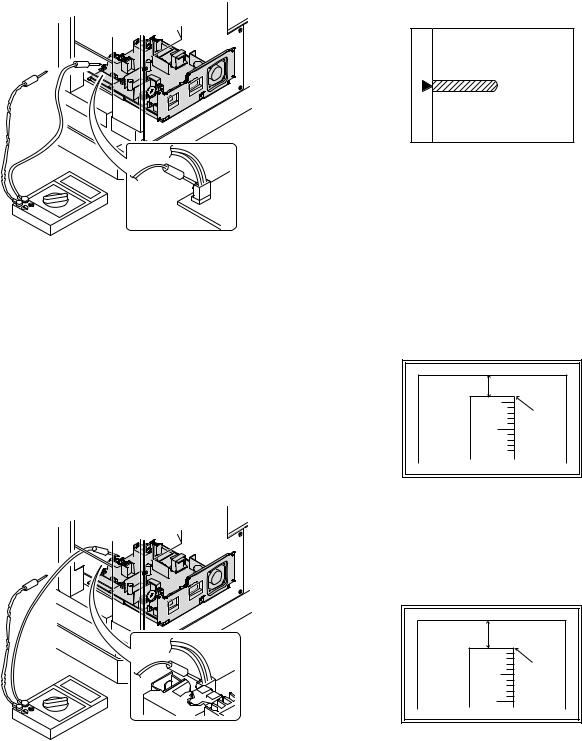
(3)Developing bias voltage check
Note:Use a digital multi-meter with an internal resistance of 10MΩ or more.
1)Set the digital multi-meter range to DC700V.
2)Put the test rod of the digital multi-meter on the developing bias voltage output check pin.
3)Turn on the power, execute SIM25-1.
<Specification>
Mode |
Specification |
|
|
Developing bias voltage |
DC - 400±8V |
|
|
(4) Grid bias voltage check
Note:Use a digital multi-meter with an internal resistance of 10MΩ or more.
1)Set the digital multi-meter range to DC700V.
2)Put the test rod of the digital multi-meter on the grid bias voltage output check pin.
3)Turn on the power.
(The voltage is outputted in the grid bias High output mode during warming up, and in the grid bias Low output mode when warming up is completed.)
<Specification>
Mode |
Specification |
|
|
Grid bias LOW |
DC - 400±8V |
|
|
Grid bias HIGH |
DC - 525±10V |
|
|
B.Mechanism section
Note: If a jam error or paper empty occurs during copying in the adjustment by the simulation, the image data are not saved, and therefore recopying is required.
(1)Image position adjustment
a.OC image lead edge position adjustment (SIM 50-1)
Note:In advance to this adjustment, the sub scanning magnification ratio adjustment must be performed.
1) Set a scale on the OC table as shown below.
2)Make a copy.
3)Check the copy output. If necessary, perform the following adjustment procedures.
4)Execute SIM 50-1.
5)Set the OC lead edge position set value (Exposure display <<PHOTO>> ON) to [1]
The OC image scanning start position is shifted inside the document edge.
6)Set the main cassette lead edge void adjustment value (Exposure display <<TEXT>> ON) * to [1]
The lead edge void becomes the minimum.
7)Set the main cassette print start position value (Exposure display <<AUTO+MAIN CASSETTE LAMP>> ON) to [1] and make a copy. The print start position is shifted inside the document edge.
5mm |
5 |
4mm |
10 |
*The dimension varies depending on the model.
8)Measure the image loss R of the copied image. Enter the set value of the image scanning lead edge position (Exposure display <<PHOTO>> ON) again.
•1 step of the set value corresponds to about 0.1mm shift. •Calculate the set value from the formula below. R/0.1(mm) = Image loss set value
<R: Image loss measurement value (mm)>
5mm |
0mm |
5 |
10 |
*The scanning edge is set.
(A line may be printed by scanning the document edge.)
Example: 4/0.1 = 40 = about 40
Note:If the set value is not obtained from the above formula, perform the fine adjustment.
AR-M205 ADJUSTMENT 6-2
9)Measure the distance H between the paper lead edge and the image print start position. Set the image print start position set value (Exposure display <<AUTO+MAIN CASSETTE LAMP>> ON) again.
•1 step of the set value corresponds to about 0.1mm shift. •Calculate the set value from the formula below. H/0.1(mm) = Image print start position set value
<H: Print start position measurement value (mm)>
0mm |
0mm |
5 |
10 |
*Fit the print edge with the paper edge, and perform the lead edge adjustment.
Example: 5/0.1 = 50 = about 50
Note:If the set value is not obtained from the above formula, perform the fine adjustment.
10) Set the lead edge void adjustment value (Exposure display <<TEXT>> ON)* again.
•1 step of the set value corresponds to about 0.1mm shift. •Calculate the set value from the formula below.
B/0.05 (mm) = Lead edge void adjustment value <B: Lead edge void (mm)>
2.5mm |
5 |
2.5mm |
10 |
Example: |
When setting the lead edge void to 2.5mm |
|
:2.5 /0.05 = about 50 |
Note:If the set value is not obtained from the above formula, perform the fine adjustment.
*2nd cassette lead edge void adjustment: Exposure display <<AUTO
+ TEXT + PHOTO>>
Multi bypass tray lead edge void adjustment: Exposure display <<TEXT + PHOTO>>
<Duplex mode adjustment>
OC 2nd print surface (Auto duplex) lead edge position adjustment: SIM50-19 <<PHOTO>>
*For the adjustment procedure, set to S → D mode before execution.
Note:Before performing the 2nd print surface lead edge position adjustment and the lead edge void adjustment, be sure to perform the 1st print surface lead edge position adjustment in advance, and be sure to perform the 2nd print surface lead edge position adjustment and then the lead edge void adjustment in this sequence.
<Adjustment specification>
Adjustment |
SIM |
LED |
Set |
Spec |
Set |
mode |
|
|
value |
value |
range |
|
|
|
|
|
|
OC image lead |
SIM |
PHOTO |
R/0.1 |
Lead edge |
1 ~ 99 |
edge position |
50-1 |
|
|
|
|
|
|
|
|
void: |
|
Main cassette |
|
AUTO |
B/0.1 |
|
|
print start |
|
+ |
|
1 - 4mm |
|
position |
|
MAIN |
|
Image loss: |
|
|
|
|
|
|
|
2nd cassette |
|
AUTO |
|
|
|
|
|
3mm or |
|
||
print start |
|
+ |
|
|
|
|
|
less |
|
||
position |
|
2nd |
|
|
|
|
|
|
|
||
|
|
CASSETTE |
|
|
|
|
|
|
|
|
|
Multi bypass |
|
AUTO |
|
|
|
tray print start |
|
+ |
|
|
|
position |
|
MULTI |
|
|
|
|
|
|
|
|
|
Lead edge void |
|
TEXT |
B/0.05 |
|
|
|
|
|
|
|
|
OC 2nd print |
SIM |
PHOTO |
1 step: |
|
|
surface lead |
50-19* |
|
0.1mm shift |
|
|
edge position |
|
|
|
|
|
adjustment |
|
|
|
|
|
|
|
|
|
|
|
*(Set to S → D mode for before execution)
b.SPF image lead edge position adjustment (SIM50-6)
1) Set a scale on the OC table as shown below.
Note:Since the printed copy is used as a test chart, put the scale in paralled with the edge lines.
2)Make a copy, Then use the copy output as an original to make an SPF copy again.
3)Check the copy output. If necessary, perform the following adjustment procedures.
4)Execute SIM 50-6.
5)Set the SPF lead edge position set value (Exposure display <<AUTO>> ON) so that the same image is obtained as that obtained in the previous OC image lead edge position adjustment.
<Adjustment specification>
Adjustment mode |
SIM |
LED |
Set value |
Spec value |
Set |
|
|
|
|
|
range |
|
|
|
|
|
|
SPF image lead |
SIM |
AUTO |
1 step: |
Lead edge |
1 ~ 99 |
edge position |
50-6 |
|
0.1mm shift |
void: |
|
(1st print surface) |
|
|
|
1 - 4mm |
|
|
|
|
|
|
|
(2nd print surface) |
|
TEXT |
|
Image loss: |
|
|
|
|
|
|
|
|
|
|
|
3mm or |
|
|
|
|
|
less |
|
|
|
|
|
|
|
AR-M205 ADJUSTMENT 6-3
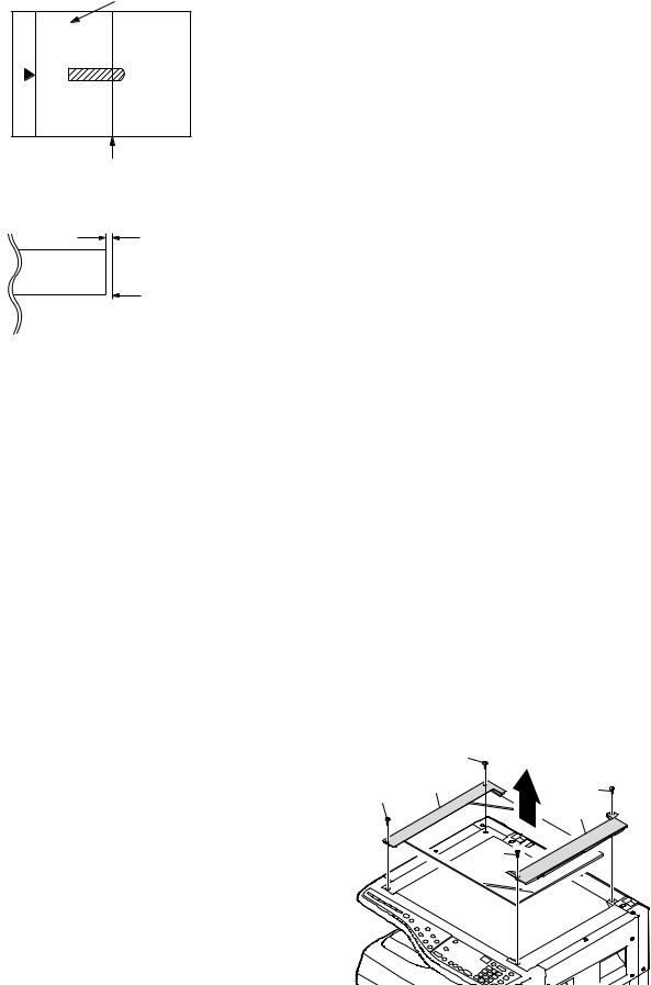
c.Rear edge void adjustment (SIM50-1, SIM50-19)
1) Set a scale as shown in the figure below.
A4(8.5" x 11")
Paper rear edge
2)Set the document size to A4 (8.5" x 11"), and make a copy at 100%.
3)If necessary, perform the following adjustment procedure.
Void amount (Standard value: 4mm or less)
Scale image
Paper rear edge
4)Execute SIM 50-1 and set the density mode to AUTO + TEXT + PHOTO (Rear edge void).The currently set adjustment value is displayed.
5)Enter the set value and press the start key. The correction value is
stored and a copy is made.
<Duplex mode adjustment>
*1st print surface (auto duplex) rear edge void adjustment: SIM50-19 <<AUTO>>
*2nd print surface (auto duplex) rear edge void adjustment: SIM50-19<<TEXT>>
*Set to S → D mode before execution.
Note:Before performing the 2nd print surface rear edge void adjustment, be sure to perform the 2nd print surface lead edge position adjustment. Never reverse the sequence.
<Adjustment specification>
Mode |
SIM |
LED |
Set value |
Specifi- |
Set |
|
|
|
|
cation |
range |
|
|
|
|
|
|
Rear edge void |
SIM |
AUTO |
1 step: |
4mm or |
1 ~ 99 |
|
50-1 |
+ |
0.1mm shift |
less |
|
|
|
TEXT |
|
|
|
|
|
+ |
|
|
|
|
|
PHOTO |
|
|
|
|
|
|
|
|
|
1st print |
SIM |
AUTO |
|
|
|
surface rear |
50-19* |
|
|
|
|
edge void |
|
|
|
|
|
|
|
|
|
|
|
2nd print |
SIM |
TEXT |
|
|
|
surface rear |
50-19* |
|
|
|
|
edge void |
|
|
|
|
|
|
|
|
|
|
|
*Set to S → D mode before execution
d. Paper off center adjustment (SIM50-10)
1)Set a test chart (UKOG-0089CSZZ) on the document table.
2)Select a paper feed port and make a copy. Compare the copy and the test chart. If necessary, perform the following adjustment procedure.
3)Execute SIM 50-10. After completion of warm-up, shading is performed and the currently set off center adjustment value of each paper feed port is displayed.
4)Enter the set value and press the start key. The correction value is stored and a copy is made.
<Duplex mode adjustment>
*2nd print surface (auto duplex) off-center adjustment: SIM50-10<<TEXT+MAIN CASSETTE>>
<Adjustment specification>
Mode |
SIM |
LED |
Set value |
Specifi- |
Set |
|
|
|
|
cation |
range |
|
|
|
|
|
|
Paper off |
SIM |
AUTO |
Add 1: |
Single: |
1 ~ 99 |
center |
50-10 |
+ |
0.1mm shift |
Center |
|
|
|
Selected |
to R side. |
±2.0mm |
|
|
|
tray ON |
|
|
|
|
|
|
Reduce 1: |
|
|
2nd print |
SIM |
TEXT |
Duplex: |
|
|
surface off- |
50-10 |
+ |
0.1mm shift |
Center |
|
center |
|
MAIN |
to L side. |
±2.5mm |
|
|
|
CASSETTE |
|
|
|
|
|
|
|
|
|
e.Side edge void area adjustment (SIM26-43)
Note:Before performing this adjustment, be sure to check that the paper off center adjustment (SIM 50-10) is completed.
1)Set a test chart (UKOG-0089CSZZ) on the document table.
2)Select a paper feed port and make two copies. Compare the 2nd copy and the test chart. If necessary, perform the following
adjustment procedure.
*The 1st copy does not show the void. Be sure to check the 2nd copy.
3)Execute SIM 26-43 and set the density mode to AUTO(right edge void) + TEXT (Left edge void).
The currently set adjustment value is displayed.
4)Enter the set value and press the start key. The correction value is stored.
<Adjustment specification>
ode |
SIM |
LED |
Set value |
Specifi- |
Set |
|
|
|
|
cation |
range |
|
|
|
|
|
|
Left edge void |
SIM |
AUTO |
1 step: |
0.5 ~ 4mm |
1 ~ 99 |
|
26-43 |
(right |
0.5mm shift |
|
|
|
|
edge) |
|
|
|
|
|
+ |
|
|
|
|
|
TEXT |
|
|
|
|
|
(left edge) |
|
|
|
|
|
|
|
|
|
*The void adjustment values on the right and the left must be the same.
(2)Main scanning direction(FR direction) distortion balance adjustment
1) Remove the OC glass and the right cabinet.
|
(1) |
(2) |
(3) |
(1) |
|
|
(4) |
|
(3) |
AR-M205 ADJUSTMENT 6-4
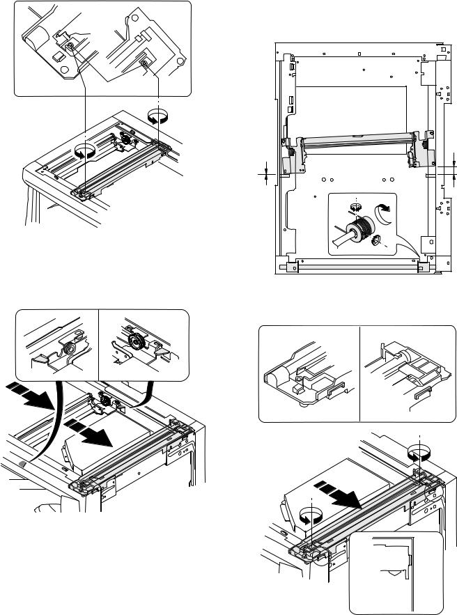
2) Loosen the copy lamp unit wire fixing screw.
4)Loosen the set screw of the scanner drive pulley which is not in contact with No. 2/3 mirror base unit positioning plate.
5)Without moving the scanner drive pulley shaft, manually turn the scanner drive pulley until the positioning plate is brought into contact with No. 2/3 mirror base unit, then fix the scanner drive pulley.
Wire fixing screw
3)Manually turn the mirror base drive pulley and bring No. 2/3 mirror base unit into contact with the positioning plate. At that time, if the front frame side and the rear frame side of No. 2/3 mirror base unit are brought into contact with the positioning plate at the same time, the mirror base unit parallelism is proper. If one of them is in contact with the positioning plate, perform the adjustment of 4).
6)Put No. 2/3 mirror base unit on the positioning plate again, push the projections on the front frame side and the rear frame side of the copy lamp unit to the corner frame, and tighten the wire fixing screw.
AR-M205 ADJUSTMENT 6-5
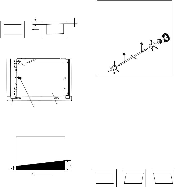
(3)Main scanning direction (FR direction) distortion adjustment
This adjustment must be performed in the following cases: •When the mirror base drive wire is replaced.
•When the lamp unit, or No. 2/3 mirror holder is replaced. •When a copy as shown is made.
La |
Lb |
Paper exit direction
Original |
Copy |
1) Set A3 (11" x 17") white paper on the original table as shown below.
Allow a little space.
Glass holding plate |
A3 (11" x 17") white paper |
|
Fit the paper edge and
the glass holding plate edge.
2)Open the original cover and make a normal (100%) copy.
3)Measure the width of the black background at the lead edge and at the rear edge.
Paper exit direction
La: Lead edge black background width
Lb: Rear edge black background width
If the width (La) of the black background at the lead edge is equal that (Lb) at the rear edge, there is no need to execute the following procedures of 4) ~ 7).
4)Loosen the mirror base drive pulley fixing screw on the front frame side or on the rear frame side.
 When La < Lb
Turn the mirror base drive pulley on the front frame side in the arrow direction A.
(Do not move the mirror base drive pulley shaft.)
 When La > Lb
Turn the mirror base drive pulley on the front frame side in the arrow direction A.
(Do not move the mirror base drive pulley shaft.)
Rear side
A
B
Front side
5)Tighten the mirror base drive pulley fixing screw.
<Adjustment specification>
La = Lb
6)Execute the main scanning direction (FR) distartion balance adjustment previously described in 2) again.
(4)Sub scanning direction (scanning direction) distortion adjustment
When there is no skew copy in the mirror base scanning direction and there is no horizontal error (right angle to the scanning direction), the adjustment can be made by adjusting the No. 2/3 mirror base unit rail height.
Before performing this adjustment, be sure to perform the horizontal image distortion adjustment in the laser scanner section.
This adjustment must be performed in the following cases: •When the mirror base wire is replaced.
•When the copy lamp unit or No. 2/3 mirror unit is replaced. •When the mirror unit rail is replaced or moved.
•When a following copy is made.
Original |
Copy A |
Copy B |
AR-M205 ADJUSTMENT 6-6
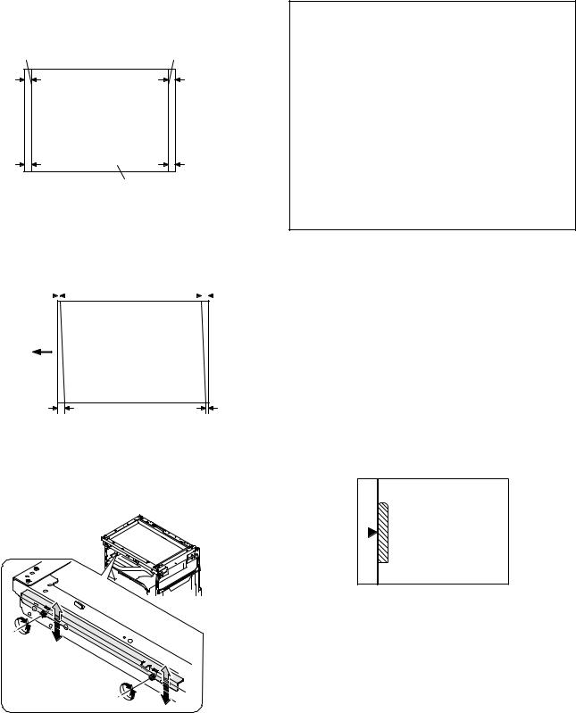
1)Making of a test sheet
Make test sheet by drawing parallel lines at 10mm from the both ends of A3 (11" x 17") white paper as shown below. (These lines must be correctly parallel to each other.)
Parallel line |
Parallel line |
10mm |
10mm |
10mm |
10mm |
White paper
2)Make a normal (100%) copy of the test sheet on A3 (11" x 17") paper. (Fit the paper edge with the glass holding plate edge.)
3)Measure the distances (La, Lb, Lc, Ld) at the four corners as shown below.
La |
|
Lc |
|
|||
|
|
|
|
|
|
|
|
|
|
|
|
|
|
Paper exit direction
Lb |
Ld |
When La = Lb and Lc = Ld, no need to perform the procedures 4) and 5).
4)Move the mirror base F rail position up and down (in the arrow direction) to adjust.
Note:If the rear side rail is used for the adjustment, the scanning position of the white balance sheet is shifted and "E7-04" may occur only when scanning with the SPF. Therefore it is advisable to use the front side rail for the adjustment.
 When La > Lb
Shift the mirror base B rail upward by the half of the difference of La - Lb.
 When La < Lb
Shift the mirror base B rail downward by the half of the difference of Lb - La.
Example: When La = 12mm and Lb = 9mm, shift the mirror base B rail upward by 1.5mm.
 When Lc > Ld
Shift the mirror base B rail downward by the half of the difference of Lc - Ld.
 When Lc < Ld
Shift the mirror base B rail downward by the half of the difference of Ld - Lc.
 When moving the mirror base rail, hold the mirror base rail with your hand.
<Adjustment specification>
La = Lb, Lc = Ld
5)After completion of adjustment, manually turn the mirror base drive pulley, scan the mirror base A and mirror base B fully, and check that
the mirror bases are not in contact with each other.
*If the mirror base rail is moved extremely, the mirror base may be in contact with the frame or the original glass. Be careful to avoid this.
(5)Main scanning direction (FR direction) magnification ratio adjustment (SIM 48-1)
Note:Before performing this adjustment, be sure to check that the CCD unit is properly installed.
1) Put a scale on the original table as shown below.
2)Execute SIM 48-1.
3)After warm-up, shading is performed and the current set value of the main scanning direction magnification ratio is displayed on the display section in 2 digits.
4)Select the mode and press the start key again.
5)Manual correction mode (TEXT lamp ON) Enter the set value and press the start key. The set value is stored and a copy is made.
AR-M205 ADJUSTMENT 6-7
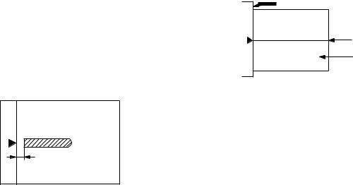
<Adjustment specification>
Note: A judgment must be made with 200mm width, and must not be made with 100mm width.
Mode |
Specification |
SIM |
Set value |
Set range |
|
|
|
|
|
Main scanning |
At normal: |
SIM 48-1 |
Add 1:0.1% |
1 ~ 99 |
direction |
±1.0% |
|
increase |
|
magnification |
|
|
Reduce 1: |
|
ratio |
|
|
0.1% |
|
|
|
|
decrease |
|
|
|
|
|
|
(6)Sub scanning direction (scanning direction) magnification ratio adjustment (SIM 48-1, SIM 48-5)
a. OC mode in copying (SIM48-1)
Note:Before performing this adjustment, be sure to check that the CCD unit is properly installed.
1)Put a scale on the original table as shown below, and make a normal (100%) copy.
2)Compare the scale image and the actual image. If necessary, perform the following adjustment procedures.
3)Execute SIM 48-1.<<PHOTO>>
4)After warm-up, shading is performed and the current set value of the main scanning direction magnification ratio is displayed on the display section in 2 digits.
5)When the photo lamp is lighted by pressing the density selection key, the current magnification ratio correction value in the sub scanning direction is displayed in lower 2 digits of the display section.
6)Enter the set value and press the start key. The set value is stored and a copy is made.
<Adjustment specification>
Mode |
Specification |
SIM |
Set value |
Set range |
|
|
|
|
|
Sub scanning |
Normal |
SIM 48-1 |
Add 1:0.1% |
1 ~ 99 |
direction |
±1.0% |
(PHOTO) |
increase |
|
magnification |
|
|
Reduce 1: |
|
ratio |
|
|
0.1% |
|
(OC mode) |
|
|
decrease |
|
|
|
|
|
|
b. RSPF sub scanning direction magnification ratio (SIM48-5)
Note:
•Before performing this adjustment, be sure to check that the CCD unit is properly installed.
•Before performing this adjustment, the OC mode adjustment in copying must be completed.
1)Put a scale on the original table as shown below, and make a normal (100%) copy to make a test chart.
Note:Since the printed copy is used as a test chart, put the scale in parallel with the edge lines.
2)Set the test chart on the SPF and make a normal (100%) copy.
3)Compare the scale image and the actual image. If necessary, perform the following adjustment procedures.
4)Execute SIM 48-5.
5)After warm-up, shading is performed.
The auto density lamp lights up and the current front surface sub scanning direction magnification ratio correction value is displayed in two digits on the display section.
6)Enter the set value and press the start key. The set value is stored and a copy is made.
7)Change the mode from the duplex original mode to the simplex original mode.
"MANUAL" lamp lights up and the current back surface sub scanning direction magnification ratio is displayed in two digits on the display section.
8)Enter the set value and press the start key. The set value is stored and a copy is made.
<Adjustment specification>
Mode |
Specification |
SIM |
Set value |
Set range |
|
|
|
|
|
Sub scanning |
Normal |
SIM 48-5 |
Add 1:0.1% |
1 ~ 99 |
direction |
±1.0% |
|
increase |
|
magnification |
|
|
Reduce 1: |
|
ratio |
|
|
0.1% |
|
(SPF mode) |
|
|
decrease |
|
|
|
|
|
|
(7) Off center adjustment (SIM 50-12)
a. OC mode (SIM50-12)
1)Make a test chart as shown below and set it so that its center line is fit with the original guide center mark.
*To make a test chart, draw a line on A3 or 11" x 17" paper at the center in the paper transport direction.
Original guide
Center
Copy paper
(A3 or 17" x 11")
2)Make a normal copy from the manual paper feed tray, and compare the copy and the test chart.
If necessary, perform the following adjustment procedures.
3)Execute SIM 50-12.
4)After warm-up, shading is performed and the current set value of the off center adjustment is displayed on the display section in 2 digits.
5)Enter the set value and press the start key. The set value is stored and a copy is made.
<Adjustment specification>
Mode |
Specification |
SIM |
Set value |
Set range |
|
|
|
|
|
Original off |
Single: |
SIM 50-12 |
Add 1: |
1 ~ 99 |
center mode |
Center ±2.0mm |
(AE lamp |
0.1mm shift |
|
(OC mode) |
|
ON) |
to R side |
|
|
|
|
Reduce 1: |
|
|
|
|
0.1mm shift |
|
|
|
|
to L side |
|
|
|
|
|
|
AR-M205 ADJUSTMENT 6-8
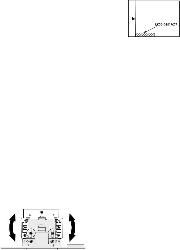
b. SPF original off-center adjustment (SIM50-12)
Note:Before performing this adjustment, be sure to check that the paper off center is properly adjusted.
1) Make a test chart for the center position adjustment and set it on the SPF.
<Adjustment specification>
Draw a line on a paper in the scanning direction.
2)Make a normal copy from the manual paper feed tray, and compare the copy and the original test chart.
If necessary, perform the following adjustment procedures.
3)Execute SIM 50-12.
4)After warm-up, shading is performed and the current set value of the off center adjustment at each paper feed port is displayed on the display section in 2 digits.
5)Enter the set value and press the start key. The set value is stored and a copy is made.
<Adjustment specification>
Mode |
Specification |
SIM |
Set value |
Set |
|
|
|
|
range |
|
|
|
|
|
Original off |
Single: |
SIM |
Add 1: |
1 ~ 99 |
center |
Center ±3.0mm(TEXT lamp) |
50-12 |
0.1mm shift |
|
mode |
|
|
to R side |
|
Duplex: |
|
|
||
(SPF mode) |
Center ±3.5mm(PHOTO lamp) |
|
Reduce 1: |
|
|
|
|
0.1mm shift |
|
|
|
|
to L side |
|
|
|
|
|
|
(8)SPF white correction pixel position adjustment(SIM63-7) (required in an SPF model when replacing the lens unit)
1)Fully open the SPF.
2)Execute SIM 63-7.
3)When the operation panel displays "COMPLETE,"the adjustment is completed.
4)If the operation panel displays "ERROR,"perform the following measures.
•When the display is 0: Check that the SPF is open.
Check that the lamp is ON.(If the lamp is OFF,check the MCU connector.) Check that the CCD harness is properly inserted into the MCU connector.
•When the display is 281 or above:
1)Remove the table glass.
2)Remove the dark box.
3)Slide the lens unit toward the front side and attach it,then execute
SIM.
•When the display is 143 or below:
1)Remove the table glass.
2)Remove the dark box.
3)Slide the lens unit toward the rear side and attach it,then execute SIM.
F R
C.Image density adjustment
(1)Copy mode (SIM 46-1)
1)Set a test chart (UKOG-0162FCZZ) on the OC table as shown below.
2)Put several sheets of A3 or 11" x 17" white paper on the test chart.
3)Execute SIM 46-1.
4)After warm-up, shading is performed and the current set value of the density level is displayed on the display section in 2 digits.
For mode selection, use the density select key.
5)Change the set value with the 10-key to adjust the copy image density.
6)Make a copy and check that the specification below is satisfied.
<Adjustment specification>
Density |
Display |
Exposure |
Sharp Gray |
Set value |
Set |
mode |
lamp |
level |
Chart output |
|
range |
|
|
|
|
|
|
Auto |
Auto |
- |
"2" is slightly |
The greater the |
1 ~ 99 |
|
|
|
copied. |
set value is the |
|
|
|
|
|
greater the |
|
Text |
Text |
3 |
"3" is slightly |
|
|
|
|
|
copied. |
density is The |
|
|
|
|
|
smaller the set |
|
Photo |
Photo |
3 |
"2" is slightly |
|
|
|
|
|
copied. |
value is the |
|
|
|
|
smaller the |
|
|
|
|
|
|
|
|
Toner |
Text/ |
3 |
"3" is slightly |
|
|
density is. |
|
||||
save |
Photo |
|
copied |
|
|
|
|
|
|
|
|
Toner |
Auto/ |
- |
"2" is slightly |
|
|
save |
Photo |
|
copied |
|
|
|
|
|
|
|
|
*When the lens unit is moved,execute the OC main scanning magnification ratio auto adjustment,SIM 48-1-1,IM48-3 and the PF original off-center adjustment.
*This adjustment is basically O.K.with IM 63-7.
AR-M205 ADJUSTMENT 6-9
[7] SIMULATIONS
1. Entering the simulation mode
Perform the following procedure to enter the simulation mode. "#" key  Interrupt key
  "C" key
  Interrupt key
  Main code
  Start key
  Sub code
  Start key
2. Canceling the simulation mode
When the clear all key is pressed, the simulation mode is cancelled. When the interruption key is pressed, the process is interrupted and the screen returns to the sub code entering display.
*After canceling the simulation mode, be sure to turn OFF/ON the power and check the operation.
Note: If the machine is terminated by a jam error or paper empty during copying in the adjustment by the simulation, recopying is required.
3. List of simulations
Main |
Sub |
Contents |
|
code |
code |
||
|
|||
|
|
|
|
01 |
01 |
Mirror scanning operation |
|
|
|
|
|
|
02 |
Mirror home position sensor (MHPS) status display |
|
|
|
|
|
|
06 |
Mirror scanning operation aging |
|
|
|
|
|
02 |
01 |
Single paper feeder (SPF) aging |
|
|
|
|
|
|
02 |
SPF sensor status display |
|
|
|
|
|
|
03 |
SPF motor operation check |
|
|
|
|
|
|
08 |
SPG paper feed solenoid operation check |
|
|
|
|
|
|
09 |
RSPF reverse solenoid operation check |
|
|
|
|
|
|
10 |
RSPF paper exit gate solenoid operation check |
|
|
|
|
|
|
11 |
SPF PS release solenoid operation check |
|
|
|
|
|
03 |
02 |
Shifter sensors status display |
|
|
|
|
|
|
03 |
Shifter operation check |
|
|
|
|
|
|
11 |
Shifter home position check |
|
|
|
|
|
05 |
01 |
Operation panel display check |
|
|
|
|
|
|
02 |
Fusing lamp and cooling fan operation check |
|
|
|
|
|
|
03 |
Copy lamp lighting check |
|
|
|
|
|
06 |
01 |
Paper feed solenoid operation check |
|
|
|
|
|
|
02 |
Resist roller solenoid operation check |
|
|
|
|
|
|
10 |
Main cassette semicircular roller cleaning |
|
|
|
|
|
07 |
01 |
Warm-up display and aging with jam |
|
|
|
|
|
|
06 |
Intermittent aging |
|
|
|
|
|
|
08 |
Shifting with warm-up display |
|
|
|
|
|
08 |
01 |
Developing bias output |
|
|
|
|
|
|
02 |
Main charger output (Grid = HIGH) |
|
|
|
|
|
|
03 |
Main charger output (Grid = LOW) |
|
|
|
|
|
|
06 |
Transfer charger output |
|
|
|
|
|
09 |
01 |
Duplex motor forward rotation check |
|
|
|
|
|
|
02 |
Duplex motor reverse rotation check |
|
|
|
|
|
|
04 |
Duplex motor RPM adjustment |
|
|
|
|
|
|
05 |
Duplex motor switchback time adjustment |
|
|
|
|
|
10 |
- |
Toner motor operation |
|
|
|
|
|
14 |
- |
Trouble cancel (except for U2) |
|
|
|
|
|
16 |
- |
U2 trouble cancel |
|
|
|
|
|
20 |
01 |
Maintenance counter clear |
|
|
|
|
|
21 |
01 |
Maintenance cycle setting |
|
|
|
|
|
|
02 |
Mini maintenance cycle setting |
|
|
|
|
|
22 |
01 |
Maintenance counter display |
|
|
|
|
|
|
02 |
Maintenance preset display |
|
|
|
|
|
|
03 |
Jam memory display |
|
|
|
|
|
|
04 |
Jam total counter display |
|
|
|
|
|
|
05 |
Total counter display |
|
|
|
|
|
|
06 |
Developing counter display |
|
|
|
|
|
|
07 |
Mini maintenance preset display |
|
|
|
|
|
|
08 |
SPF counter display |
|
|
|
|
|
|
09 |
Paper feed counter display |
|
|
|
|
|
|
12 |
Drum counter display |
|
|
|
|
|
|
13 |
CRUM type display |
|
|
|
|
|
|
14 |
P-ROM version display |
|
|
|
|
|
|
15 |
Trouble memory display |
|
|
|
|
|
|
16 |
Duplex print counter display |
|
|
|
|
|
|
17 |
Copy counter display |
|
|
|
|
|
|
18 |
Printer counter display |
|
|
|
|
|
|
19 |
Scanner mode counter display |
|
|
|
|
|
|
21 |
Scanner counter display |
|
|
|
|
|
|
22 |
SPF jam counter display |
|
|
|
|
AR-M205 SIMULATIONS 7-1
 Loading...