


SHARP AR-FN8, AR-FN9, AR-PN2A, AR-PN2B, AR-PN2C Service Manual
...SERVICE MANUAL
CODE : 00ZARFN8//A1E
FINISHER
PUNCH UNIT
AR-PN2
MODEL
AR-FN8 |
AR-FN9 |
CONTENTS
AR-FN8 AR-FN9 AR-PN2A AR-PN2B AR-PN2C AR-PN2D
[1] GENERAL DESCRIPTION . . . . . . . . . . . . . . . . . . . . . . . . . . . . . 1-1 [2] FINISHER UNIT BASIC OPERATION. . . . . . . . . . . . . . . . . . . . . 2-1 [3] SADDLE STICHER UNIT BASIC OPERATION . . . . . . . . . . . . . 3-1 [4] PUNCHER UNIT BASIC OPERATION . . . . . . . . . . . . . . . . . . . . 4-1 [5] MECHANICAL CONSTRUCTION . . . . . . . . . . . . . . . . . . . . . . . . 5-1 [6] MAINTENANCE AND INSPECTION. . . . . . . . . . . . . . . . . . . . . . 6-1 [7] TROUBLESHOOTING . . . . . . . . . . . . . . . . . . . . . . . . . . . . . . . . 7-1 [8] UNPACKING AND INSTALLATION . . . . . . . . . . . . . . . . . . . . . . . 8-1
Parts marked with “ “ are important for maintaining the safety of the set.
Be sure to replace these parts with specified ones for maintaining the safety and performance of the set.
This document has been published to be used for SHARP CORPORATION after sales service only.
The contents are subject to change without notice.

INTRODUCTION
This Service Manual contains the basic data and figures for the Finisher AR-FN8/Saddle Finisher AR-FN9 needed to service the machine in the field.
This manual comprises the following chapters:
Chapter 1 “General Description” introduces the finisher’s features, specifications, and names of parts, and shows how to operate the finisher.
Chapter 2 “Finisher Unit Basic Operation” discusses the principles of operation used for the finisher mechanical and electrical systems. It also explains the timing at which these systems are operated.
Chapter 3 “Saddle Finisher Unit Basic Operation” discusses the principles of operation used for the saddle stitcher unit’s mechanical and electrical systems. It also explains the timing at which these systems are operated.
Chapter 4 “Puncher (option) Unit Basic Operation” discusses the principles of operation used for the puncher unit’s mechanical and electrical systems. It also explains the timing at which these systems are operated.
Chapter 5 “Mechanical System” discusses how the finisher is constructed mechanically, and shows how it may be disassembled/assembled and adjusted.
Chapter 6 “Maintenance and Inspection” provides tables of periodically replaced parts and consumables and durables, together with a scheduled servicing chart.
Chapter 7 “Troubleshooting” shows how to troubleshoot possible faults and gives electrical parts arrangement diagrams, LED/check pin diagrams by PCB.
“Appendix” contains diagrams showing tables of signals, overall circuit diagrams and tables of solvents/oils.
Descriptions of installation are not mentioned in this Service Manual as the Finisher/ Saddle Finisher’s packing boxes contain Installation Procedures.
The descriptions in this Service Manual are subject to change without notice for product improvement or other purposes, and major changes will be communicated in the form of Service Information bulletins.
All service persons are expected to have a good understanding of the contents of this Service Manual and all relevant Service Information bulletins, and be able to identify and isolate faults in the machine.
i
ii

CONTENTS
CHAPTER 1 GENERAL DESCRIPTION
I. FEATURES .................................. |
1-1 |
E. |
Supplying the Saddle Stitcher |
|
|
II. SPECIFICATIONS ....................... |
1-2 |
|
Unit with Staples (Saddle |
|
|
A. |
Finisher specification ................ |
1-2 |
|
Finisher) ................................. |
1-22 |
B. |
Punch unit specification ......... |
1-10 |
F. |
Removing Staple Jams |
|
C. Cross Section ......................... |
1-13 |
|
from the Saddle Stitcher Unit |
|
|
III. Using the Machine ..................... |
1-16 |
|
(Saddle Finisher) .................... |
1-23 |
|
A. Removing Paper Jams |
|
G. |
Removing Paper Jams from |
|
|
|
from the Finisher Unit ............. |
1-16 |
|
the Puncher Unit (option) ....... |
1-25 |
B. Supplying the Finisher Unit |
|
H. |
Removing Punched Scrap |
|
|
|
with Staples ............................ |
1-17 |
|
from the Puncher Unit |
|
C. Removing Staple Jams from |
|
|
(option) ................................... |
1-26 |
|
|
the Finisher Unit ..................... |
1-19 |
IV. MAINTENANCE BY THE |
|
|
D. Removing Paper Jams from |
|
USER ........................................ |
1-27 |
||
|
the Saddle Stitcher Unit |
|
A. Maintenance by the User ....... |
1-27 |
|
|
(Saddle Finisher) .................... |
1-20 |
|
|
|
CHAPTER 2 FINISHER UNIT BASIC OPERATION
I. BASIC OPERATION .................... |
2-1 |
|
A. |
Outline ...................................... |
2-1 |
B. |
Outline of Electrical |
|
|
Circuitry .................................... |
2-2 |
C. Inputs to and Outputs from the |
||
|
Finisher Controller PCB ........... |
2-4 |
II. FEED/DRIVE SYSTEM ............. |
2-10 |
|
A. Outline .................................... |
2-10 |
|
B. Type of Delivery Paths ............ |
2-15 |
|
C. Feeding and Delivering .......... |
2-18 |
|
D. |
Job Offset ............................... |
2-21 |
E. |
Stapling Operation ................. |
2-24 |
F. |
Stapler Unit ............................ |
2-32 |
G. Tray Operation ........................ |
2-38 |
|
H. Detecting the Height of |
|
|
|
Stack on the Tray .................... |
2-40 |
I. |
Shutter Operation ................... |
2-42 |
J. |
Buffer Path Operation ............. |
2-46 |
K. Detecting Jams ...................... |
2-51 |
|
III. POWER SUPPLY SYSTEM ....... |
2-56 |
|
iii

CHAPTER 3 SADDLE STITCHER UNIT
BASIC OPERATION
I. BASIC OPERATION .................... |
3-1 |
|
A. |
Outline ...................................... |
3-1 |
B. |
Electrical Circuitry .................... |
3-2 |
C. Inputs to and Outputs from |
|
|
|
the Saddle Stitcher Controller |
|
|
PCB .......................................... |
3-3 |
II. FEEDING/DRIVE SYSTEM ......... |
3-8 |
|
A. |
Outline ...................................... |
3-8 |
III. PAPER OUTPUT |
|
|
MECHANISM ............................. |
3-14 |
|
A. |
Outline .................................... |
3-14 |
B. |
Controlling the Inlet |
|
|
Flappers ................................. |
3-17 |
C. Controlling the Movement of |
|
Sheets .................................... |
3-21 |
D. Aligning the Sheets ................ |
3-23 |
E. Controlling the Phase of the |
|
Crescent Roller ...................... |
3-26 |
IV. STITCHING SYSTEM ............... |
3-29 |
V. FOLDING/DELIVERY |
|
SYSTEM .................................... |
3-32 |
VI. CHECKING FOR A JAM............ |
3-40 |
VII. POWER SUPPLY ...................... |
3-45 |
CHAPTER 4 PUNCHER UNIT (OPTION)
BASIC OPERATION
I. BASIC OPERATION .................... |
4-1 |
|
A. |
Outline ...................................... |
4-1 |
B. |
Inputs to and Outputs from Punch |
|
|
Driver PCB ............................... |
4-2 |
II. PUNCH OPERATION .................. |
4-5 |
|
A. |
Outline ...................................... |
4-5 |
B. |
PUNCH OPERATION ............... |
4-7 |
C. |
Horizontal Registration |
|
|
Operation ............................... |
4-11 |
III. POWER SUPPLY SYSTEM ....... |
4-14 |
|
CHAPTER 5 MECHANICAL CONSTRUCTION
I. FINISHER UNIT .......................... |
5-1 |
B. |
SADDLE UNIT ....................... |
5-22 |
A. Externals and Controls ............. |
5-1 |
C. |
PCBs ...................................... |
5-32 |
B. FEEDING SYSTEM ................. |
5-8 |
III. PUNCHER UNIT (OPTION) ...... |
5-33 |
|
C. PCBs ...................................... |
5-16 |
A. |
Externals and Controls ........... |
5-33 |
II. SADDLE STITCHER UNIT ........ |
5-17 |
B. |
Puncher Driver System .......... |
5-34 |
A. Externals and Controls ........... |
5-17 |
C. |
PCBs ...................................... |
5-39 |
iv

CHAPTER 6 MAINTENANCE AND INSPECTION
I. PERIODICALLY REPLACED |
|
|
PARTS ......................................... |
6-1 |
|
A. |
Finisher Unit ............................. |
6-1 |
B. |
Saddle Stitcher Unit ................. |
6-1 |
C. |
Puncher Unit (option) ............... |
6-1 |
II. CONSUMABLES AND |
|
|
DURABLES ................................. |
6-2 |
|
A. |
Finisher Unit ............................. |
6-2 |
B. |
Saddle Stitcher Unit ................. |
6-2 |
C. Puncher Unit (option) ............... |
6-2 |
|
III. PERIODICAL SERVICING .......... |
6-2 |
|
CHAPTER 7 TROUBLESHOOTING
I. ADJUSTMENTS .......................... |
7-1 |
A. |
Finisher Unit ........................... |
7-10 |
|
A. |
Electrical System |
|
B. |
Saddle Stitcher Unit ............... |
7-18 |
|
(finisher unit) ............................ |
7-1 |
C. |
Puncher Unit (option) ............. |
7-26 |
B. |
Electrical System (saddle |
|
D. |
Light-Emitting Diodes (LED) and |
|
|
stitcher unit) .............................. |
7-3 |
|
Check Pins by PCB ................ |
7-30 |
C. Electrical System (puncher |
|
IV. TROUBLESHOOTING ............... |
7-32 |
||
|
unit (option)) ............................. |
7-5 |
A. |
Finisher Unit ........................... |
7-32 |
II. TEST MODE ................................ |
7-7 |
B. |
Saddle Stitcher Unit ............... |
7-42 |
|
A. |
Finisher Unit ............................. |
7-7 |
C. |
Puncher Unit (option) ............. |
7-50 |
B. |
Saddle Stitcher Unit ................. |
7-8 |
|
|
|
III. ARRANGEMENT OF ELECTRICAL |
|
|
|
||
PARTS ....................................... |
7-10 |
|
|
|
|
CHAPTER 8 UNPACKING AND INSTALLATION
I. FINISHER .................................... |
8-1 |
II. PUNCH UNIT .............................. |
8-6 |
v

APPENDIX
A. |
SIGNAL AND |
|
E. |
SADDLE STITCHER UNIT |
|
|
ABBREVIATIONS ....................... |
A-1 |
|
PCB .......................................... |
A-17 |
B. |
FINISHER UNIT CIRCUIT |
|
F. |
PUNCHER UNIT (OPTION) |
|
|
DIAGRAM ................................... |
A-2 |
|
CIRCUIT DIAGRAM ................. |
A-25 |
C. FINISHER CONTROLLER |
|
G. PUNCH DRIVER PCB .............. |
A-26 |
||
|
PCB ............................................ |
A-5 |
H. SOLVENT AND OIL .................. |
A-29 |
|
D. |
SADDLE STITCHER UNIT |
|
|
|
|
|
CIRCUIT DIAGRAM ................. |
A-15 |
|
|
|
vi

CHAPTER 1
GENERAL DESCRIPTION
I. FEATURES ................................ |
1-1 |
E. Supplying the Saddle Stitcher |
||
II. SPECIFICATIONS ..................... |
1-2 |
Unit with Staples (Saddle |
|
|
A. |
Finisher specification ........... |
1-2 |
Finisher) ............................. |
1-22 |
B. |
Punch unit specification ..... |
1-10 |
F. Removing Staple Jams |
|
C. Cross Section..................... |
1-13 |
from the Saddle Stitcher Unit |
||
III. Using the Machine ................... |
1-16 |
(Saddle Finisher) ................ |
1-23 |
|
A. Removing Paper Jams |
|
G. Removing Paper Jams from |
||
|
from the Finisher Unit ......... |
1-16 |
the Puncher Unit (option) ... |
1-25 |
B. Supplying the Finisher Unit |
|
H. Removing Punched Scrap |
|
|
|
with Staples........................ |
1-17 |
from the Puncher Unit |
|
C. Removing Staple Jams from |
(option) ............................... |
1-26 |
||
|
the Finisher Unit ................. |
1-19 |
IV. MAINTENANCE BY THE |
|
D. Removing Paper Jams from |
|
USER ....................................... |
1-27 |
|
|
the Saddle Stitcher Unit |
|
A. Maintenance by the User ... |
1-27 |
|
(Saddle Finisher) ................ |
1-20 |
|
|

CHAPTER 1 GENERAL DESCRIPTION
I.FEATURES
1.Accommodates large quantities of sheets.
•Normally, the finisher holds a stack of sheets 147 mm in height in its two bins (small-size paper: equivalent to 1000 sheets)/74 mm in height (large-size paper: equivalent to 500 sheets)
2.Has high paper transportation performance.
•The finisher is capable of handling paper between 60 and 200 g/m2.
3.Offers a job offset function.
•The finisher has a job offset function for sorting non-stapled stacks of copies.
4.Offers four types of auto stapling.
•The finisher offers a choice of four stapling modes (1-point stapling at rear, diagonal stapling at front, diagonal stapling at rear, 2-point stapling).
5.Uses a buffer roller.
•The use of a buffer roller enables the finisher to accept copies without interruption from the host machine even during stapling or offset operation.
6.Has a saddle stitch function (Saddle Finisher).
•The finisher can staple along the center of paper and fold it in two (up to 15 sheets).
7.Offers a punch function (option).
•The use of the puncher unit enables the finisher to punch sheets for binders before they are output. (The puncher unit is capable of handling papers between 64 and 200 g/m2. It cannot handle special paper, postcards and transparencies.)
ITEM |
MODEL |
|
|
|
NOTE |
|
|
|
|
|
|
Finisher |
AR-FN8 |
|
|
|
|
|
|
|
|
|
|
|
|
|
|
|
|
|
|
|
|
|
|
Finisher |
AR-FN9 |
|
Finsher with Saddle Stitching |
|
|
|
|
|
|
||
|
|
|
|
|
|
|
|
|
|
|
|
Punch unit |
AR-PN2A |
|
2 holes (80mm pitch) |
|
|
|
Europe |
|
|
||
|
|
|
|
|
|
|
|
|
|
|
|
|
AR-PN2B |
|
2 holes (70mm pitch) 3 holes (108mm pitch) |
USA/Canada |
|
|
|||||
|
|
|
|
|
|
|
|
|
|
|
|
|
AR-PN2C |
|
4 holes (80mm pitch) |
|
|
|
France |
|
|
||
|
|
|
|
|
|
|
|
|
|
|
|
|
AR-PN2D |
|
4 holes (70/21mm pitch) |
|
|
|
Sweden |
|
|
||
|
|
|
|
|
|
|
|
|
|
|
|
|
|
|
|
|
|
|
|
|
|
||
Stapler for Finisher |
Staple Cartrige |
x1 |
5000×3 |
SF-SC11 |
|
20 |
|
Cartridge for AR-FN8 and AR-FN9 |
|||
5000 sheets |
|
|
|
|
Common w ith S55,S55N |
||||||
|
|
|
|
|
|
|
|
|
|
||
Stapler for Finisher |
Staple Cartrige |
x1 |
5000×3 |
SF-SC3 |
|
40 |
|
|
AR-FN8 and AR-FN9 |
||
2000 sheets |
|
|
|
|
(For AR-FN9 Saddle Stitch) |
||||||
|
|
|
|
|
|
|
|
|
|
||
|
|
|
|
|
|
|
|
|
|
|
|
1-1

CHAPTER 1 GENERAL DESCRIPTION
II. SPECIFICATIONS
A.Finisher specifications
1.Basic specifications
a.General
Type |
2-tray finisher * Stretching paper exit tray |
|
|
Installation type |
Floor installation, field option |
|
|
Fixing method |
Latch method (Fixed with brackets in the upper side of the PPC exit |
|
side) |
|
|
Vertical adjustment feature |
Available |
|
|
Distribution system |
Tray shift system |
|
|
Paper entry port height |
683.5mm from the floor surface |
|
|
b.Tray section
(1)Functions (Mode)
Simple load (Non-sort) |
Paper sheets of a same size are loaded in the specified bin in |
|
|
|
the non-sort mode. |
|
|
|
Job offset load (Sort/Group) |
Discharged paper bundles are shifted back and forth to sort. |
|
|
|
|
Staple load |
Stapling is automatically performed. |
|
|
|
|
Mixed load |
Size mixed load |
Paper sheets of different sizes are loaded in the specified bin. |
|
|
(In the sort/group mode, only sheets of a same width can be |
|
|
loaded.) |
|
|
|
|
Staple mixed load |
Paper sheets of different sizes (of a same width) are stapled |
|
|
and loaded in a same bundle in the staple mode. |
|
|
|
(2) Applicable paper
Size and load height [mm] |
*1 |
|
|
Weight |
Normal paper: 60 - 200g/m2 |
Kinds |
Normal paper, recycled paper |
|
Special paper: Conforming to the body specifications. |
|
|
Curl level |
10mm or less |
|
|
Stacking size |
AB : A3, A4, A4-R, A5-R, B4, B5, B5-R |
|
Inch : LD, LG, LT, LT-R, FOLIO, COMPUTER |
|
|
*1: Paper sizes and load height are shown below.
1-2
CHAPTER 1 GENERAL DESCRIPTION

 In the case of simple load, job offset load, and staple load
Mode |
|
Single load (Non-sort) |
Job offset load (Sort/Group) |
Staple load |
||||
Tray No. |
|
1 |
2 |
1 |
2 |
1 |
2 |
|
|
|
|
|
|
|
|
||
A5 long, ST long |
147mm |
147mm |
X |
X |
X |
X |
||
|
|
|
|
|
|
|
|
|
B5 long |
|
74mm |
74mm |
X |
X |
X |
X |
|
|
|
|
|
|
|
|
|
|
A4 short, |
|
|
|
|
|
110mm, 750 |
110mm, 750 |
|
|
|
|
|
|
sheets, or 50 |
sheets, or 50 |
||
B5 short, |
|
147mm |
147mm |
147mm |
147mm |
|||
|
sets, whichever |
sets, whichever |
||||||
LT short |
|
|
|
|
|
|||
|
|
|
|
|
is reached first. |
is reached first. |
||
|
|
|
|
|
|
|||
A4 long, |
B4 long, |
|
|
|
|
74mm, 500 |
74mm, 500 |
|
A3 long, |
LT long, |
74mm |
74mm |
74mm |
74mm |
sheets, or 50 |
sheets, or 50 |
|
LG long, LD long, |
sets, whichever |
sets, whichever |
||||||
|
|
|
|
|||||
FOLIO, |
COMP |
|
|
|
|
is reached first. |
is reached first. |
|
Measuring sensor
Paper transport direction
 [Paper load height]
Stack tray

 In the case of size/staple mixed load Mode
Mode |
|
Size mixed load |
|
Staple mixed load |
||
Setup |
Non-sort |
Sort |
Group |
Staple at one point |
Staple at 2 points |
|
Mixed load of |
74mm |
X |
X |
X |
X |
|
different widths |
||||||
|
|
|
|
|
||
|
|
|
|
74mm, 500 sheets, |
74mm, 500 sheets, |
|
Mixed load of A3 |
74mm |
74mm |
74mm |
or 50 sets, |
or 50 sets, |
|
and A4 |
|
|
|
whichever is |
whichever is |
|
|
|
|
|
reached first. |
reached first. |
|
|
|
|
|
74mm, 500 sheets, |
74mm, 500 sheets, |
|
Mixed load of B4 |
74mm |
74mm |
74mm |
or 50 sets, |
or 50 sets, |
|
and B5 |
|
|
|
whichever is |
whichever is |
|
|
|
|
|
reached first. |
reached first. |
|
|
|
|
|
74mm, 500 sheets, |
74mm, 500 sheets, |
|
Mixed load of LD |
74mm |
74mm |
74mm |
or 50 sets, |
or 50 sets, |
|
and LT |
|
|
|
whichever is |
whichever is |
|
|
|
|
|
reached first. |
reached first. |
|
|
|
|
|
74mm, 500 sheets, |
74mm, 500 sheets, |
|
Mixed load of LG |
74mm |
74mm |
74mm |
or 50 sets, |
or 50 sets, |
|
and LT-R |
|
|
|
whichever is |
whichever is |
|
|
|
|
|
reached first. |
reached first. |
|
1-3

CHAPTER 1 GENERAL DESCRIPTION
c.Staple section
Type |
|
Unit assembly type |
|
|
|
Staple load system |
Staple cartridge (5,000 staples) |
|
|
|
|
Installation |
|
Inside of the front cover |
|
|
|
Fixing |
|
Magnet catch |
|
|
|
Stapling capacity |
(A4 short, B5 short, LT short): 50 sheets |
|
|
|
(A3 long, B4 long, A4 long, LD long, LT long, FOLIO, |
|
|
COMPUTER): 30 sheets |
|
|
|
Stapling direction |
Face-up stapling |
|
|
|
|
Basic functions |
Auto stapling |
Stapling is automatically performed for every number of |
|
|
sheets specified in the staple sort mode. |
|
|
|
|
Stapleemptydetection |
Staple empty in the staple cartridge is automatically detected |
|
|
by the photo sensor. |
|
|
|
Applicablepaper |
Size |
* One-point staple in the front |
|
|
A3 long, B4 long, A4 (long/short), B5 short, LD long, LG |
|
|
long, LT (long/short), FOLIO, COMPUTER |
|
|
* One-point staple at that back |
|
|
A4 long, LG long, LT long, COMPUTER |
|
|
* One-point staple at the back (Slant staple) |
|
|
A3 long, B4 long, A4 short, B5 short, LD long, LT short |
|
|
* Two-point staple |
|
|
A3 long, B4 long, A4 (long/short), ‚a5 short, LD long, LT |
|
|
(long/short), COMPUTER, LG long, FOLIO |
|
|
|
|
Weight |
64 - 80g/m2 |
|
Kinds |
Normal paper, recycled paper |
|
|
|
1-4
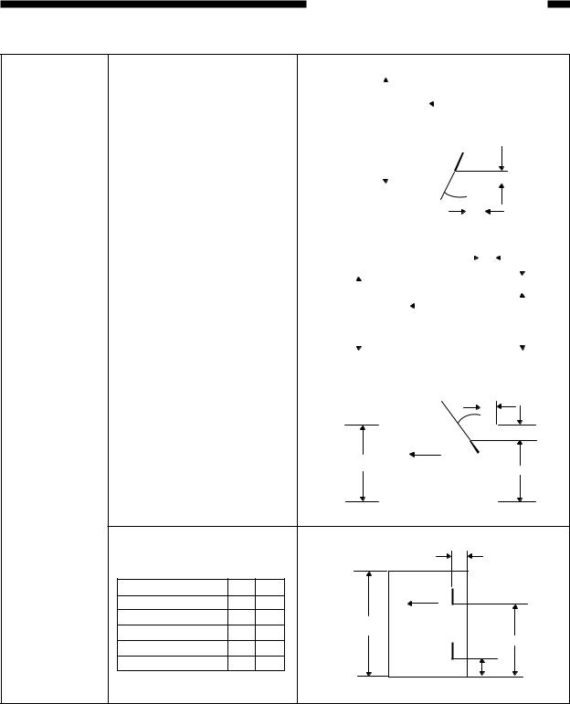
CHAPTER 1 GENERAL DESCRIPTION
Stapling position One-point staple in the front |
|
|
|
|
|
|
|
|
|
|
|
|
|
|
|
|
|
|
|
|
|
|
|
|
||||
|
|
|
|
|
|
|
|
|
|
|
|
|
|
|
|
|
|
|
|
|
|
|
|
|
|
|
|
|
|
|
|
|
|
|
|
|
|
|
|
|
|
|
Paper feeding |
|
|
|
|
|
|
|
|
|
|||||
|
|
|
|
|
|
|
|
|
|
|
|
|
|
direction |
|
|
|
|
|
|
|
|
|
|
|
|||
|
|
|
|
|
|
|
|
|
|
|
|
|
|
|
|
|
|
|
|
|
|
|
|
|
|
|
|
|
|
|
|
|
|
|
|
|
|
|
|
|
|
|
|
|
|
|
|
|
|
|
|
|
|
|
|
||
|
|
* Stapling position range: |
|
|
Paper width |
|
|
|
|
|
|
|
|
|
|
|
|
|
|
|
|
|||||||
|
|
|
|
|
|
|
|
|
|
|
|
|
|
|
|
|
|
|
|
|
|
|
|
|
|
|||
|
|
The specified value ± 4mm |
|
|
|
|
|
|
|
|
|
|
|
|
|
|
|
|
4.4 |
|
|
|
|
|
||||
|
|
|
|
|
|
|
|
|
|
|
|
|
|
|
|
|
|
|
|
|
|
|||||||
|
|
|
|
|
|
|
|
|
|
|
|
|
|
|
|
|
|
|
|
|
|
|
|
|
|
|||
|
|
|
|
|
|
|
|
|
|
|
|
|
|
|
|
|
|
|
|
|
|
|
|
|
|
|||
|
|
|
|
|
|
|
|
|
|
|
|
|
|
(30˚) |
4.4 |
|
|
|
|
|
|
|
|
|
||||
|
|
|
|
|
|
|
|
|
|
|
|
|
|
|
|
|
|
|
|
|
|
|
|
|
|
|
||
|
|
|
|
|
|
|
|
|
|
|
|
|
|
|
|
|
|
|
|
|
|
|
|
|
|
|
|
|
|
One-point staple at that back |
|
|
|
|
|
|
|
|
|
|
|
|
|
|
|
|
|
|
|
|
|
|
|
|
|||
|
|
|
|
|
|
|
|
|
|
|
|
|
|
|
|
|
|
|
|
5.0 |
|
|
|
|
|
|
|
|
|
|
|
|
|
|
|
|
|
|
|
|
|
|
|
|
|
|
|
|
|
|
|
|
|
||||
|
|
|
|
|
|
|
|
|
|
|
|
|
|
|
|
|
|
|
|
|
|
|
|
|
|
|
|
|
|
|
|
|
|
|
|
|
|
|
|
Paper feeding |
|
|
|
6.0 |
|
|
|||||||||||
|
|
Size |
A |
|
|
|
|
|
|
|
|
direction |
|
|
|
|
|
|
|
|
|
|
|
|||||
|
Paper width |
|
|
|
|
|
|
|
|
|
|
|
|
|
|
|||||||||||||
|
|
A4-Long, FOLIO |
204.0 |
|
|
|
|
|
|
|
|
|
|
|
|
|
|
|
|
|
|
|
||||||
|
|
|
|
|
|
|
|
|
|
|
|
|
|
|
|
|
|
|
|
|
||||||||
|
|
|
|
|
|
|
|
|
|
|
|
|
|
|
|
|
|
|
|
|
|
A |
||||||
|
|
LG-Long, LT-Long |
210.0 |
|
|
|
|
|
|
|
|
|
|
|
|
|
|
|
|
|
|
|
|
|||||
|
|
|
|
|
|
|
|
|
|
|
|
|
|
|
|
|
|
|
|
|
|
|
|
|
|
|||
|
|
|
|
|
|
|
|
|
|
|
|
|
|
|
|
|
|
|
|
|
|
|
|
|
||||
|
|
|
|
|
|
|
|
|
|
|
|
|
|
|
|
|
|
|
|
|
|
|
|
|
|
|
|
|
|
|
|
|
|
|
|
|
|
|
|
|
|
|
|
|
|
|
|
|
|
|
|
|
|
|
|
|
|
|
|
|
|
|
|
|
|
|
|
|
|
|
|
|
|
|
|
|
|
|
|
|
|
|
|
|
|
|
|
|
|
|
|
|
|
|
|
|
|
|
|
|
|
|
|
|
|
|
|
|
|
|
|
|
|
|
|
|
One-point staple at the back |
|
|
|
|
|
|
|
|
|
|
|
(30˚) |
|
|
|
|
|
|
|
|
|
|
|
||||
|
(Slant staple) |
|
|
|
|
|
|
|
|
|
|
|
|
|
|
4.0 |
|
|
|
|
|
|
|
|
||||
|
|
|
|
|
|
|
|
|
|
|
|
|
|
|
|
|
|
|
|
|
|
|
||||||
|
|
|
|
|
|
|
|
|
|
|
|
|
|
|
|
|
|
|
|
|
|
|
|
|||||
|
|
|
|
|
|
|
|
|
|
|
|
|
|
|
|
6.0 |
|
|
||||||||||
|
|
|
|
|
|
|
|
|
|
|
Paper feeding |
|
|
|
|
|
|
|||||||||||
|
|
Size |
|
A |
|
|
|
|
|
|
|
|
direction |
|
|
|
|
|
|
|
|
|
|
|
||||
|
|
A3 long, A4 short |
|
291.0 |
Paper width |
|
|
|
|
|
|
|
|
|
|
|
|
|
|
|
A |
|||||||
|
|
|
|
|
|
|
|
|
|
|
|
|
||||||||||||||||
|
|
B4 long, B5 short |
|
251.0 |
|
|
|
|
|
|
|
|
|
|
|
|
|
|
|
|
|
|
|
|
||||
|
|
|
|
|
|
|
|
|
|
|
|
|
|
|
|
|
|
|
|
|
|
|
|
|
|
|
||
|
|
|
|
|
|
|
|
|
|
|
|
|
|
|
|
|
|
|
|
|
|
|
|
|
|
|
|
|
|
|
LD long, LT short |
|
273.5 |
|
|
|
|
|
|
|
|
|
|
|
|
|
|
|
|
|
|
|
|
|
|
|
|
|
|
|
|
|
|
|
|
|
|
|
|
|
|
|
|
|
|
|
|
|
|
|
|
|
|
|
|
|
|
|
|
|
|
|
|
|
|
|
|
|
|
|
|
|
|
|
|
|
|
|
|
|
|
|
|
|
|
Two-point staple |
|
|
|
|
|
|
|
5.0 |
|
Size |
A |
B |
Paper feeding |
|
direction |
||||
A3 long, L4 short |
83.0 |
203.0 |
||
|
||||
A4 long, FOLIO |
62.5 |
138.5 |
Paper width |
|
B4 long, B5 short, COMP |
63.0 |
183.0 |
||
B |
||||
LD long, LT short |
74.0 |
194.0 |
||
|
||||
LT long, LG LONG |
62.5 |
144.5 |
A |
|
|
|
|
1-5

CHAPTER 1 GENERAL DESCRIPTION
d.Saddle stitch section (AR-FN9 only)
Staple type |
|
Unit assembly type |
||||||
Staple load |
|
Staple cartridge (2,000 staples) |
||||||
|
|
|
|
|
|
|
|
|
Staple empty detection |
|
Available |
||||||
|
|
|
|
|
|
|
|
|
Installing direction |
|
Inside of the front lower cover |
||||||
|
|
|
|
|
|
|
|
|
Stapling capacity |
|
15 sheets |
||||||
|
|
|
|
|
|
|
|
|
Stapling system |
|
Center stapling, two-fold, |
||||||
|
|
* Fixed stapling pitch |
||||||
|
|
|
|
|
|
|
|
|
Folding position |
|
Center folding |
||||||
|
|
* Sheet center adjustment function provided |
||||||
|
|
|
|
|
|
|
|
|
Applicable paper |
|
A3 long, B4 long, A4 long, LD long, LT long |
||||||
|
|
|
|
|
|
|
|
|
Size |
Weight |
64 - 80g/m2 |
||||||
|
|
* Cover only: 64 - 200g/m2 |
||||||
|
Kind |
Normal paper, recycled paper |
||||||
|
|
|
|
|
|
|
|
|
|
Load capacity |
Bundle of 11 - 15 sheets: 10 sets |
||||||
|
|
Bundle of 6 - 10 sheets: 20 sets |
||||||
|
|
Bundle of 5 sheets or less: 25 sets |
||||||
|
|
* No stapling for one-folding |
||||||
|
|
|
|
|
|
|
|
|
Stapling position |
|
|
|
|
|
|
±1.0mm or less |
|
|
|
|
|
|
|
|
||
|
|
|
|
|
||||
|
|
|
|
|
|
|
||
|
|
|
|
|
|
|
|
|
|
|
|
|
|
|
|
|
|
|
|
|
|
|
|
|
|
|
|
|
|
|
|
|
|
|
|
|
|
|
|
|
|
|
|
|
|
|
|
|
|
|
|
|
|
B
|
|
|
|
|
|
|
|
|
|
|
|
|
|
|
|
|
|
|
|
|
|
|
|
A |
||
|
|
|
|
|
|
|
|
|
|
|
|
|
|
|
|
|
|
Size |
|
|
|
A |
|
B |
|
|
|
|
|
|
|
||||
A3 long |
|
|
|
83.0 |
203.0 |
|
||
|
|
|
|
|
||||
B4 long |
|
|
|
63.0 |
183.0 |
|
||
|
|
|
|
|
||||
A4 long |
|
|
|
39.5 |
159.5 |
|
||
|
|
|
|
|
||||
LD long |
|
|
|
74.0 |
194.0 |
|
||
|
|
|
|
|
||||
LT long |
|
|
|
42.0 |
162.0 |
|
||
1-6

CHAPTER 1 GENERAL DESCRIPTION
2.Machine specifications
External dimensions |
Machine external |
W599 x D615 x H1014mm |
|
dimensions |
* Excluding the connection rail and the |
|
|
projection. With no punch, with latch unit |
|
|
installed, with sub tray closed. |
|
|
|
|
Package external |
W1162 x D817 x H951m |
|
dimensions |
* Including the cardboard pallet |
|
|
|
Weight |
Machine weight |
About 32kg (AR-FN8) About 52kg (AR-FN9) |
|
|
* Machine body (excluding the connection |
|
|
rail) |
|
|
|
|
Package weight |
About 86kg |
|
|
* Shipping condition |
|
|
|
Packed items |
|
Finisher unit (1) |
|
|
Installing bracket (1) |
|
|
Rail (1) |
|
|
Latch hold plate (1) |
|
|
Positioning bracket (1) |
|
|
Tray (2) |
|
|
Harness cover (Large) (1) |
|
|
Harness cover (Small) (1) |
|
|
Latch unit (1) |
|
|
Latch unit lower cover (1) |
|
|
IPC board (1) |
|
|
Locking support (1) |
|
|
Staple position label (1) |
|
|
Entry port mylar (1) |
|
|
TPPAN screw M4x6 (4) |
|
|
BID screw with washer M4x6 (1) |
|
|
BID screw with washer M4x20 (4) |
|
|
DIS screw with washer M4x16 (2) |
|
|
Step screw (4) |
|
|
BID screw M4x14 (1) |
|
|
BID screw M4x6 (2) |
|
|
|
3.Electrical specifications
Input voltage |
DC24V±10% supplied from PPC |
|
|
4.Environment conditions
Operating conditions |
Temperature |
10 - 30°C (without dew) |
||
|
|
|
|
|
|
Humidity |
20 |
- 85%RH (without dew) |
|
|
|
|
||
Transit/storage |
Temperature |
-10 - 30°C (without dew) |
||
conditions |
|
|
|
|
Humidity |
20 |
- 85% RH (without dew) |
||
|
||||
|
|
|
|
|
1-7
CHAPTER 1 GENERAL DESCRIPTION
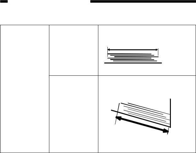
5. |
Reliability |
|
|
Stack alignment |
Side shift |
Non-sort, sort, group |
|
[Stack section] |
|
L1: 30mm or less |
|
|
|
|
A |
|
|
|
L1=A - Paper width |
|
|
Lead edge shift |
Non-sort, sort, group |
|
|
|
L2: 50mm or less |
|
|
|
Non-sort, sort, group |
|
|
|
B |
|
|
|
L2=B - Paper length |
(1)Excluding ST-R, A5-R, B5-R
(2)Bundle identification must be valid in the job offset mode.
(3)Side shift quantity is the value at the back edge of paper.
(4)Excluding unexpected error of non-conformity of the standards
(5)Alignment of 750 sheets or more is out of the above specifications.(Loadable)
(6)Alignment of mixed sizes is out of the above specifications. (Loadable)
6.Conforming standards
Safety standards |
(1) UL |
|
|
(2) |
C-UL |
|
(3) |
TUV |
|
(4) |
CE (Applied by Sharp) |
|
|
|
Obstruction wave standards |
(19 VCCI (As a system) |
|
|
(2) |
FCC (IC) (As a system) |
|
|
|
1-8

CHAPTER 1 GENERAL DESCRIPTION
7.System comparison of AR-S650/650

 Paper size and load height (cascade setup)
Mode |
Simple load (Non-sort/group) |
Job offset load (Sort) |
Staple load |
||||
Tray no. |
1 |
2 |
1 |
2 |
1 |
2 |
|
A5 long, ST long |
X |
X |
X |
X |
X |
X |
|
B5 long |
X |
X |
X |
X |
X |
X |
|
|
|
|
|
|
93mm, 637 |
93mm, 637 |
|
A4 short, |
|
|
|
|
sheets, or 42 |
sheets, or 42 |
|
B5 short, |
X |
X |
125mm |
125mm |
sets, whichever |
sets, whichever |
|
LT short |
|
|
|
|
is reached |
is reached |
|
|
|
|
|
|
first. |
first. |
|
A4 long, B4 long, |
|
|
|
|
63mm, 425 |
63mm, 425 |
|
A3 long, |
|
|
|
|
|||
|
|
|
|
sheets, or 42 |
sheets, or 42 |
||
LT long, |
|
|
|
|
|||
X |
X |
63mm |
63mm |
sets, whichever |
sets, whichever |
||
LG long, |
|||||||
|
|
|
|
is reached |
is reached |
||
LD long, FOLIO, |
|
|
|
|
|||
|
|
|
|
first. |
first. |
||
COMP |
|
|
|
|
|||
|
|
|
|
|
|
||

 Paper size and load height (cascade setup) in mixed load
Mode |
|
Size mixed load |
|
Staple mixed load |
||
Setup |
Non-sort |
Sort |
Group |
One-point staple |
Two-point staple |
|
Different width |
X |
X |
X |
X |
X |
|
mixed |
||||||
|
|
|
|
|
||
|
|
|
|
63mm, 425 sheets, |
63mm, 425 sheets, |
|
A3 and A4 mixed |
X |
63mm |
X |
or 42 sets, |
or 42 sets, |
|
whichever is |
whichever is |
|||||
|
|
|
|
|||
|
|
|
|
reached first. |
reached first. |
|
|
|
|
|
63mm, 425 sheets, |
63mm, 425 sheets, |
|
B4 and B5 mixed |
X |
63mm |
X |
or 42 sets, |
or 42 sets, |
|
whichever is |
whichever is |
|||||
|
|
|
|
|||
|
|
|
|
reached first. |
reached first. |
|
|
|
|
|
63mm, 425 sheets, |
63mm, 425 sheets, |
|
LD and LT mixed |
X |
63mm |
X |
or 42 sets, |
or 42 sets, |
|
whichever is |
whichever is |
|||||
|
|
|
|
|||
|
|
|
|
reached first. |
reached first. |
|
|
|
|
|
63mm, 425 sheets, |
63mm, 425 sheets, |
|
LG and LT-R |
X |
63mm |
X |
or 42 sets, |
or 42 sets, |
|
mixed |
whichever is |
whichever is |
||||
|
|
|
||||
|
|
|
|
reached first. |
reached first. |
|
1-9

CHAPTER 1 GENERAL DESCRIPTION
B.Punch unit specifications
1.Basic specifications
a.General
Installation type |
|
Field option |
|
|
|
|
|
Number of |
|
2-hole (Ø6.5) |
Japan, Europe |
punch holes and |
|
|
|
|
2-hole/3-hole |
North America |
|
hole dia. |
|
||
|
auto selection |
|
|
* For details of |
|
|
|
|
(Ø8.0) |
|
|
punch positions, |
|
|
|
|
|
|
|
|
4-hole (Ø6.5) |
France (80mm pitch) |
|
refer to the next |
|
||
|
|
|
|
page. |
|
4-hole (Ø6.5) |
Sweden (70, 21mm pitch) |
|
|
|
|
Punch position adjustment |
Punch hole pitch is fixed. |
||
|
|
|
Punch position adjustment in the back and forth direction is |
|
|
|
provided. |
|
|
|
|
Allowable |
|
2-hole |
A3 long, B4 long, A4 (long/short), B5 (long/short), FOLIO, |
punch size |
|
|
LD long, LG long, LT (long/short), COMPUTER |
|
|
|
|
|
|
2-hole/3-hole |
A3 long, A4 short, LD long, LT short (3-hole), LG long, LT |
|
|
auto selection |
long, COMPUTER (2-hole) |
|
|
|
|
|
|
4-hole (F) |
A3 long, A4 short, LD long, LT short |
|
|
|
|
|
|
4-hole (S) |
A3 long, B4 long, A4 (long/short), B5 (long/short), FOLIO, |
|
|
|
LD long, LG long, LT (long/short), COMPUTER |
|
|
|
|
Punch dust full detection |
Available |
||
|
|
|
* Punch dust full and jam are displayed on the copier display. |
|
|
|
|
Allowable weight for punch |
64 - 200g (OHP sheet or special paper cannot be used.) |
||
|
|
|
|
Punch life |
|
1 million sheets (80g paper) |
|
|
|
|
|
Display section |
|
Not provided. |
|
|
|
|
|
Operation panel |
|
Not provided |
|
|
|
|
* The punch mode can be set with the operation panel of the |
|
|
|
copier. |
|
|
|
|
1-10
CHAPTER 1 GENERAL DESCRIPTION

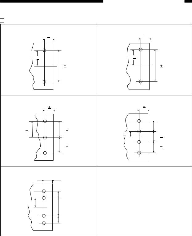
 Punch position (Unit : mm)
2-hole ( Ø 6.5) : Japan/Europe (80mm pitch) |
2-hle ( Ø 8.0) : North America (70mm pitch) |
|||||||||
12 |
3 |
|
|
12 |
|
3 |
|
|
||
|
|
|
|
|||||||
|
|
|
|
|
|
|
|
|
|
|
|
|
|
|
|
|
|
|
|
|
|
40 |
3 |
|
35 |
3 |
|
|
80 |
1 |
|
70 |
1 |
3-hole ( Ø 8.0) : North America |
4-hole ( Ø 6.5) : France |
|
|
|||||
12 |
3 |
|
|
12 |
3 |
|
||
|
|
|
|
|
|
|||
|
|
|
|
|
|
|
|
|
(80  1)
1)
108 |
3 |
108 |
1 |
40 3
(80 1)
108 |
1 |
(80 |
1) |
|
|
4-hole ( Ø 6.5) Sweden
12  3
3
(21  1)
1)
35  3
3
(70  1)
1)
(21  1)
1)
1-11

CHAPTER 1 GENERAL DESCRIPTION
2.Machine specifications
External dimensions |
Machine external |
W76 x D581x H373mm |
|
dimensions |
* Punch dimension does not include the punch |
|
|
lower cover. |
|
|
|
|
Package external |
W726 x D514 x H339mm |
|
dimensions |
|
|
|
|
Weight |
Machine weight |
About 6kg |
|
|
|
|
Package weight |
About 11kg |
|
|
|
Package weight |
|
Punch unit body (1) |
|
|
Punch lower cover (1) |
|
|
Jam process label (1) |
|
|
Saddle jam process label (1) |
|
|
Connector cover (1) |
|
|
Body cover stopper (1) |
|
|
Step screw (long) (1) |
|
|
Step screw (short) (2) |
|
|
BID screw M4x16 (1) |
|
|
BID screw M4x6 (3) |
|
|
|
3.Electrical specifications
Input voltage |
DC24±V10% supplied from PPC |
|
|
4.Environment conditions
Operating conditions |
Temperature |
10 |
- 30 ° C (without dew) |
|
|
|
|
|
|
|
Humidity |
20 |
- 85%RH (without dew) |
|
|
|
|
||
Transit/storage |
Temperature |
-10 - 30 ° C (without dew) |
||
conditions |
|
|
|
|
Humidity |
20 |
- 85% RH (without dew) |
||
|
||||
|
|
|
|
|
1-12
CHAPTER 1 GENERAL DESCRIPTION
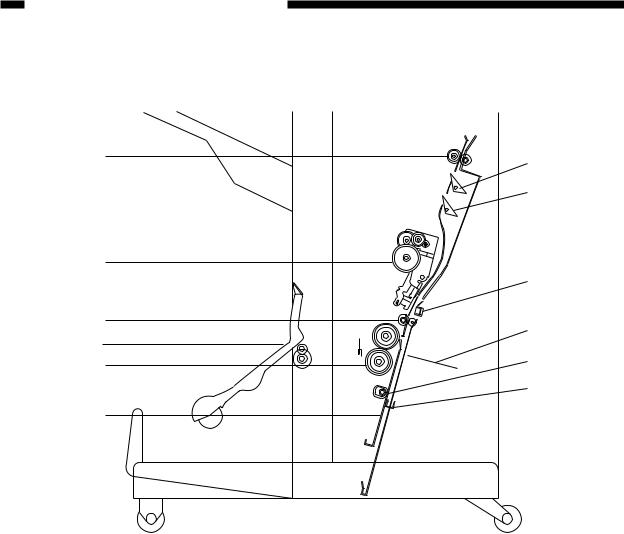
C.Cross Section
1.Finisher Unit
[1] |
[2] [3] [4] [5] [6] |
[7] |
[8] [9] |
[10] [11] [18] [19] |
||
|
|
|
|
|
|
|
|
|
|
|
|
|
|
|
|
|
|
|
|
|
|
|
|
|
|
|
|
|
|
|
|
|
|
|
[17] [16] [15] [14] [13] [12]
[1]Tray 1/2
[2]Shutter
[3]Delivery roller
[4]Swing guide
[5]Feed roller 2
[6]Height sensor
[7]Wrap flapper
[8]Buffer roller
[9]Buffer inlet flapper
[10]Saddle stitcher flapper
[11]Inlet feed roller
[12]Feed roller 1
[13]Vertical path
[14]Stapler
[15]Knurled belt
[16]Tray lift motor
[17]Saddle stitcher unit (Saddle Finisher)
[18]Latch unit
[19]Inlet feed section
Figure 1-204
1-13
CHAPTER 1 GENERAL DESCRIPTION
2.Saddle Stitcher Unit
[6] |
[7] |
|
|
|
[8] |
[5]
[9]
[4]
[10]
[3] [2] 
 [11]
[11]
[12]
[1]
[1] |
Guide plate |
[7] |
No. 1 flapper |
[2] |
Folding roller |
[8] |
No. 2 flapper |
[3] |
Delivery guide plate |
[9] Stitcher plate (front, rear) |
|
[4] |
Holding roller |
[10] |
Butting plate |
[5] |
Stitcher (front, rear) |
[11] |
Crescent roller |
[6] |
Inlet roller |
[12] |
Paper positioning plate |
Figure 1-205
1-14

CHAPTER 1 GENERAL DESCRIPTION
3.Puncher Unit (option)
[1]
[2]
[3]
 [5] [4]


 [6]
[6]
[7]
[8]
[9]
[1]Punch motor
[2]Cam
[3]Hole puncher (Punch blade)
[4]Die
[5]Photosensor PCB
[6]LED PCB
[7]Horizontal registration motor
[8]Scrap-full detector PCB unit
[9]Punched scrap container
Figure 1-206
1-15

CHAPTER 1 GENERAL DESCRIPTION
IV. USING THE MACHINE
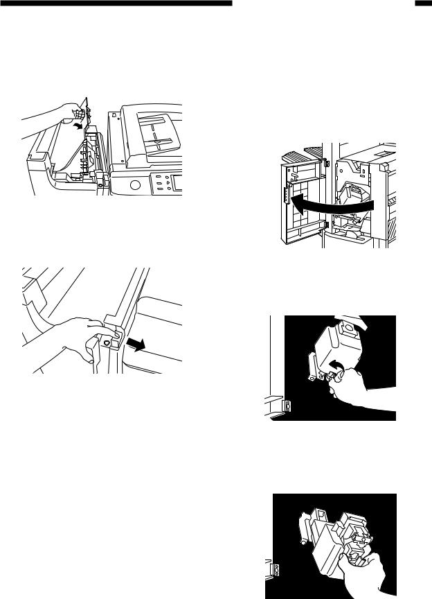
A.Removing Paper Jams from the Finisher Unit
If the host machine indicates the finisher paper jam message, perform the following to remove the jam.
1)Holding the latch lever down as shown, move it to detach it from the host machine.
Figure 1-301
2) Remove any jam visible from the outside.
Figure 1-302
3)Open the upper cover and check the inside of the finisher.
Figure 1-303
4)Lift the buffer roller cover and remove the jam.
Figure 1-304
5) Lift the buffer roller and remove the jam.
Figure 1-305
1-16
6)Return the buffer roller and the buffer roller cover to their original positions, and close the upper cover.
Figure 1-306
7) Connect the finisher to the host machine.
Figure 1-307
8)Operate as instructed on the display.
CHAPTER 1 GENERAL DESCRIPTION
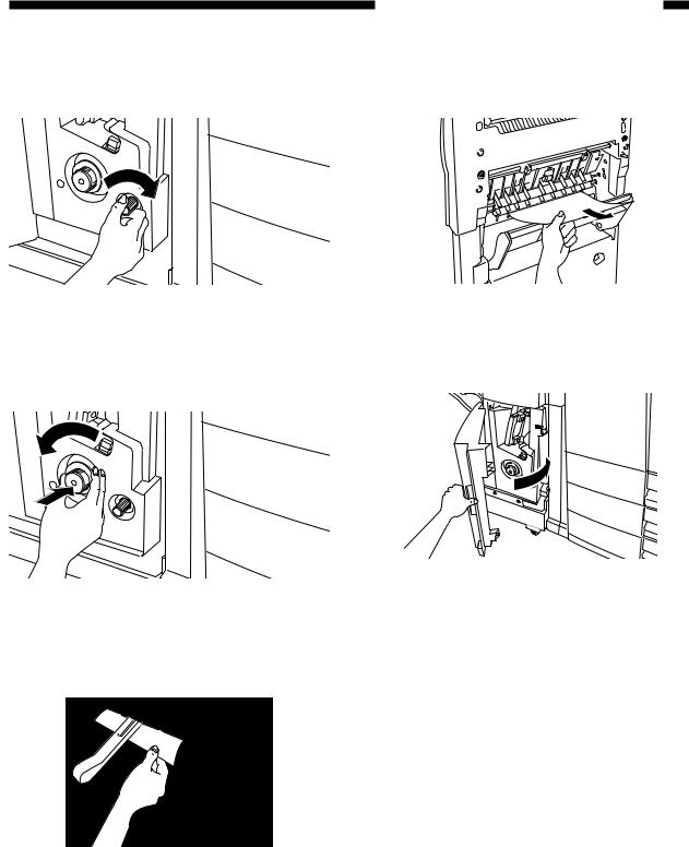
B.Supplying the Finisher Unit with Staples
If the copier indicates the finisher unit staple supply message, perform the following to supply it with staples.
1) Open the front door.
Figure 1-308
2) Turn the blue knob counterclockwise.
Figure 1-309
3)Draw out the staple unit, and pull put the staple cartridge.
Figure 1-310
1-17
CHAPTER 1 GENERAL DESCRIPTION
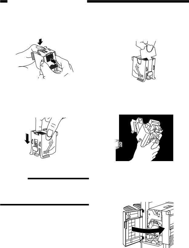
4)Push the blue knob and pull out the empty staple case.
Figure 1-311
5) Set a new staple case.
Figure 1-312
Reference:
You may set no more than one staple cartridge at a time.
Make sure that the new cartridge is one specifically designed for the finisher unit.
*Do not tear off the seal which fixes the staples before setting them in the cartridge.
6)Pull the length of tape (used to hold the staples in place) straight out.
Figure 1-313
7) Set the staple cartridge.
Figure 1-314
8)Push in the stapler unit completely until it stops and turn the blue knob clockwise to lock it and close the front door.
Figure 1-315
1-18
C.Removing Staple Jams from the Finisher Unit
If the copier indicates the finisher unit staple jam message, perform the following to remove the jam.
1)Remove the stack waiting to be stapled from the delivery tray.
Figure 1-316
2) Open the front door.
Figure 1-317
3) Turn the blue knob counterclockwise.
Figure 1-318
CHAPTER 1 GENERAL DESCRIPTION
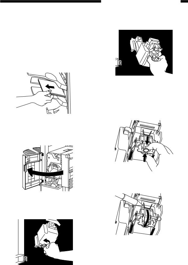
4) Draw out the stapler unit and then lift it up.
Figure 1-319
5)Remove the lock of the stopper and open the staple cover.
*Lift up the metal knob softly to open the staple cover.
Figure 1-320
6) Remove the jammed staples.
Figure 1-321
7) Push down the metallic knob and close the
1-19
CHAPTER 1 GENERAL DESCRIPTION
staple cover.
8)Return the stapler unit to its original position, and turn the blue knob clockwise to lock it.
Figure 1-322
9) Close the front door.
Reference:
When the door has been closed, the stapler unit will automatically execute idle punching several times to advance the staples.
D.Removing Paper Jams from the Saddle Stitcher Unit (Saddle Finisher)
If the host machine indicates the saddle stitcher unit paper jam message, perform the following to remove the jam.
1)Holding the latch lever down unit as shown, move it to detach it from the host machine.
Figure 1-323
2) Open the front lower door.
Figure 1-324
1-20
3) Turn the knob clockwise.
Figure 1-325
4)Turn the knob counterclockwise while pushing it in.
Figure 1-326
5) Remove the jam.
Figure 1-327
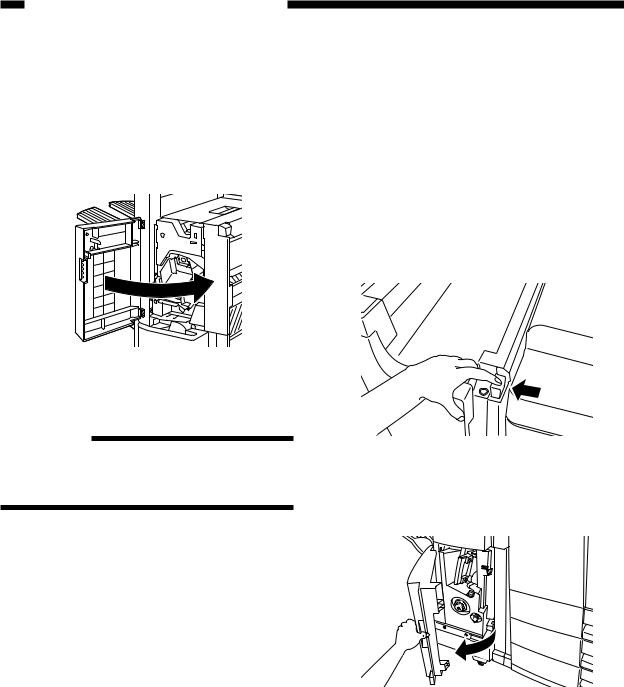
CHAPTER 1 GENERAL DESCRIPTION
6) Open the inlet cover and remove the jam.
Figure 1-328
7) Close the front lower door.
Figure 1-329
8)Connect the saddle finisher to the host machine.
9)Operate as instructed on the display.
1-21
CHAPTER 1 GENERAL DESCRIPTION
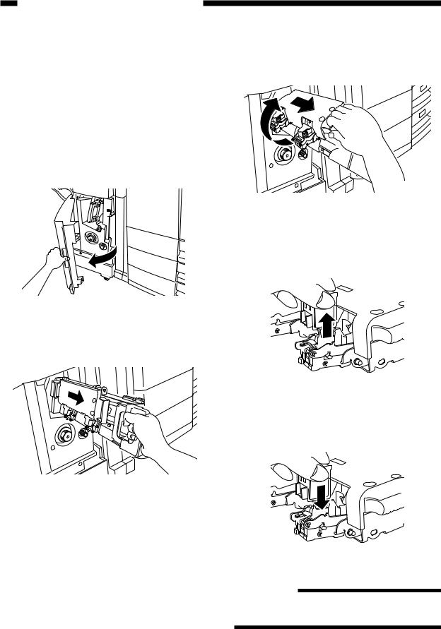
E.Supplying the Saddle Stitcher Unit with Staples (Saddle Finisher)
If the host machine indicates the saddle stitcher unit staple supply message, perform the following to supply it with staples.
1) Open the front lower door.
3)Pull the stitcher unit to the front once and then shift it up.
Figure 1-332
4) Hold the empty cartridge on its sides and remove it.
Figure 1-330
2) Slide out the stitcher unit.
Figure 1-333
5) Set a new cartridge.
Figure 1-331
Figure 1-334
Reference
You must always replace both cartridges at the same time.
1-22
 Loading...