


 Loading...
q SERVICE MANUAL
CODE : 00ZARD28//A1E
AR-MU2
AR-D28
LASER PRINTER OPTIONS
PAPER FEED UNIT
OPTIONAL POWER SUPPLY UNIT
AR-D27
AR-D28
AR-D27
MODEL AR-MU2
CONTENTS
[1] |
PRODUCT OUTLINE . . . . . . . . . . . . . . . . . . . . . . . . . . . . . . . . . |
1 - 1 |
[2] |
CONFIGURATION . . . . . . . . . . . . . . . . . . . . . . . . . . . . . . . . . . . |
2 - 1 |
[3] |
SPECIFICATIONS . . . . . . . . . . . . . . . . . . . . . . . . . . . . . . . . . . . |
3 - 1 |
[4] |
UNPACKING AND INSTALLATION . . . . . . . . . . . . . . . . . . . . . . |
4 - 1 |
[5] EXTERNAL VIEWS AND INTERNAL STRUCTURES . . . . . . . . |
5 - 1 |
|
[6] |
ADJUSTMENTS . . . . . . . . . . . . . . . . . . . . . . . . . . . . . . . . . . . . . |
6 - 1 |
[7] DISASSEMBLY AND ASSEMBLY, MAINTENANCE . . . . . . . . . |
7 - 1 |
|
[8]BLOCK DIAGRAM, WIRING DIAGRAM,
CIRCUIT DIAGRAM, PARTS ARRANGEMENT . . . . . . . . . . . . . 8 - 1
PARTS GUIDE
Parts marked with "!" are important for maintaining the safety of the set. Be sure to replace these parts with specified ones for maintaining the safety and performance of the set.
|
|
|
This document has been published to be used |
SHARP CORPORATION |
for after sales service only. |
The contents are subject to change without notice. |
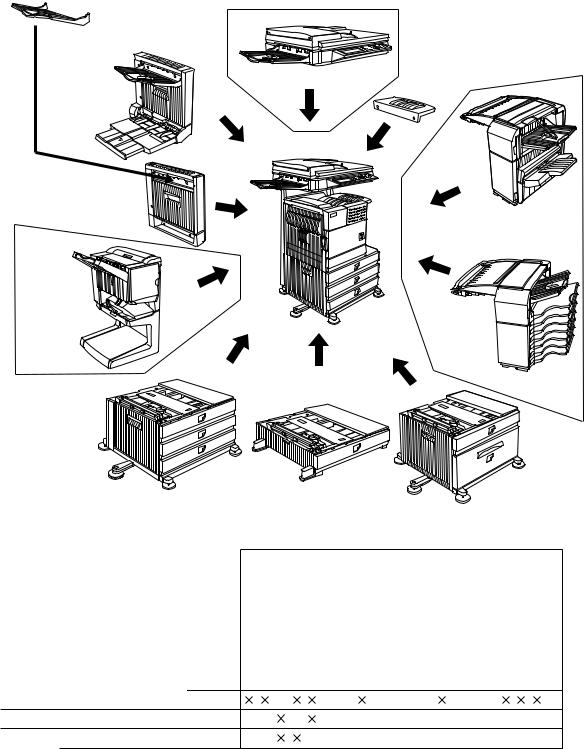
[1] PRODUCT OUTLINE
This unit is installed to one of the following machines to serve as a Paper feed module.
When installing the unit to one of the following machines, one of the multi-purpose tray (AR-MU2), the large capacity paper feed desk (AR-D28), and the 3-stage paper feed desk (AR-D27) must be installed in advance.
Applicable models |
AR-M351N/M451N/M355N/M455N |
|
AR-M351U/M451U/M355U/M455U |
|
|
[2] CONFIGURATION
1. The AR-MU2 cannot be installed together with the saddle finisher (AR-FN7)/Scanner unit (AR-EF3).
Exit tray |
|
(AR-TE3 or AR-DU4 Standard) |
B/W scanner module/DSPF(AR-EF3) |
|
|
Duplex |
|
module/bypass tray |
Upper exit tray |
|
extension |
|
(AR-TE4) |
Finisher
(AR-FN6)
Duplex module (AR-DU3)
Saddle stitch |
Mail-bin |
finisher |
|
(AR-FN7) |
stacker |
|
(AR-MS1) |
|
Multi purpose drawer |
|
(AR-MU2) |
Stand/3 x 500 sheet |
|
|
paper drawer |
Stand/MPD & 2000 sheet |
|
(AR-D27) |
||
paper drawer |
||
|
||
|
(AR-D28) |
Related to paper feed unit
Multi purpose drawer |
AR-MU2 |
Stand/3 x 500 sheet paper drawer |
AR-D27 |
Stand/MPD & 2000 sheet paper drawer |
AR-D28 |
|
|
B/W scanner module/DSPF |
Scanner rack |
|
Multi purpose drawer |
|
Stand/3 x 500 sheet paper drawer |
|
Stand/MPD & 2000 sheet |
Duplex module/bypass tray |
Duplex module |
Saddle stitch finisher |
Finisher |
Mail-bin stacker |
Exit tray |
Upper exit tray extension |
Punch unit |
Multi-function controller board |
Print server card |
PS3 expansion kit |
Network scanner expansion kit |
Facsimile expansion kit |
Fax memory (8 MB) |
Hard disk drive |
|||
|
|
|
|
|
|
|
|
|
|
|
|
|
|
|
|
|
|
|
|
|
|
|
|
|
|
|
|
|
|
|
|
|
|
|
|
|
|
|
|
|
|
|
|
|
|
|
|
|
|
|
|
|
|
|
|
|
|
|
|
|
|
|
|
|
|
|
|
|
|
|
|
|
|
|
|
|
|
|
|
|
|
|
|
|
|
|
|
|
|
|
|
|
|
|
|
|
|
|
|
|
|
|
|
AR-D28/D27/MU2 PRODUCT OUTLINE
1 – 1
[3] SPECIFICATIONS
1. AR-D28
|
|
|
|
AR-D28 |
|
|
|
|
|
||
Type |
|
Stand MPD&2000 Sheet Paper Drawer |
|||
|
|
|
(large capacity tray + multi purpose drawer) |
||
|
|
|
|||
Transport speed |
To support 35-45 sheet/minute |
||||
|
|
|
|||
Transport alignment |
Center alignment |
||||
|
|
|
|
||
Paper size |
1 Tray |
A3, B4, A4, A4R, B5, B5R, A5R |
|||
|
|
|
11"x17", 8.5"x14", 8.5"x13", 8.5"x11", |
||
|
|
|
8.5"x11"R, 5.5"x8.5"R |
||
|
|
|
Executive, Japanese p/c, Monarch(envelope) |
||
|
|
|
Com-10(envelope), DL(envelope), |
||
|
|
|
C5(envelope), ISO B5(envelope) |
||
|
|
|
|
||
|
|
2 Tray |
A4, 8.5" x 11" |
||
|
|
|
|
||
How to change |
|
Guide adjustment by user/ |
|||
the paper size |
|
Software setting by user |
|||
|
|
|
|
|
|
F a c t o r y |
1 Tray |
8.5" x 11" |
|
||
default paper |
|
|
|
||
|
2 Tray |
The size guide plate is packed together. |
|||
size setting |
|
|
|
||
Media avail- |
1 Tray |
Plain paper |
: 60-128g/m² / 16-34lbs |
||
able for paper |
|
Index paper : 176g/m² / 47lbs |
|||
feeding |
|
Cover paper : 200-205g/m² / 54-55lbs |
|||
|
|
|
Envelope |
: 75-90g/m², 20-24lbs |
|
|
|
|
Transparency film |
||
|
|
|
*Media heavier than 105g/m² should be |
||
|
|
|
A4/8.5x11" or smaller. Media heavier than |
||
|
|
|
128g/m² should be fed from shorter edge. |
||
|
|
|
*Only single paper feed is enabled for over- |
||
|
|
|
lay copy or copy on back-side of printed |
||
|
|
|
paper. |
|
|
|
|
|
|
||
|
|
2 Tray |
Plain 60-105g/m² / 16-28lbs |
||
|
|
|
|||
Paper capacity |
1 Tray |
Standard: 500sheets(80g/m²) |
|||
|
|
|
Post card: 40sheets |
||
|
|
|
Envelope: 40sheets |
||
|
|
|
Transparency film: 40sheets |
||
|
|
|
|
||
|
|
2 Tray |
880+1,320sheets (64g/m²) / |
||
|
|
|
800+1,200sheets (80g/m²) |
||
|
|
|
|||
Paper type |
1 Tray |
Plain, recycled, pre-printed, pre-punched, |
|||
|
|
|
color, letter head, labels, heavy, transpar- |
||
|
|
|
ency, Japanese p/c, envelope |
||
|
|
|
(User can set bi-type for each of the above |
||
|
|
|
paper type.) |
|
|
|
|
|
|
||
|
|
2 Tray |
Plain, recycled, pre-printed, pre-punched, |
||
|
|
|
color, letter head (User can set bi-type for |
||
|
|
|
each of the above paper type.) |
||
|
|
|
|||
Sizes to be |
1 Tray |
Auto detection-AB: |
|||
detected |
|
A3, B4, A4, A4R, B5, B5R, 8.5"x13", A5R |
|||
|
|
|
|
||
|
|
|
Auto detection-Inch: |
||
|
|
|
11"x17", 8.5"x14", 8.5"x11", 8.5"x11"R, |
||
|
|
|
7.25"x10.5"R, 5.5" x 8.5R |
||
|
|
|
|
||
|
|
|
Manual (input detection): |
||
|
|
|
postal card, Monarch(envelope), |
||
|
|
|
Com-10(envelope), DL(envelope), |
||
|
|
|
C5(envelope), ISO B5(envelope) |
||
|
|
|
|
||
|
|
|
Ignore detection selectable: |
||
|
|
|
|
||
|
|
2 Tray |
Size setting by the serviceman |
||
|
|
|
|||
P a p e r b a l - |
1 Tray |
Provided (paper empty and 3 steps) |
|||
ance detec- |
|
|
|
|
|
|
2 Tray |
Enable (Paper empty and |
|||
tion |
|||||
|
6 steps (3 steps + 3 steps)) |
||||
|
|
|
|||
|
|
|
|
|
|
|
|
AR-D28 |
|
|
|
Paper loading system |
To be loaded from the upper side with |
|
|
|
front loading system |
|
|
|
Tray ascent/ |
Ascent |
Within 12 seconds |
descent time |
|
|
|
At paper empty, required time from |
|
|
|
|
|
|
tray insert to the empty detection |
|
|
|
|
Descent |
Own weight descent |
|
|
|
Dehumidification heater |
Not provided |
|
|
|
|
Power consumption |
32.2W or lower |
|
|
|
|
Power source |
Supplied from main unit |
|
|
|
(DC24V 1.3A / DC5V 0.2A) |
|
|
|
External dimensions |
589 x 630 x 404 (mm) |
|
|
|
|
Occupied dimensions |
963 x 665 (mm) |
|
|
|
|
Weight |
Approx. 34kg |
|
|
|
|
2. AR-D27
|
|
|
AR-D27 |
|
|
|
|
Type |
|
Stand /3x500 Sheet Paper Drawer |
|
|
|
(2 paper trays + 1 multi purpose drawer) |
|
|
|
||
Transport speed |
To support 35-45 sheet/minute |
||
|
|
||
Transport alignment |
Center alignment |
||
|
|
|
|
Paper size |
1 Tray |
A3, B4, A4, A4R, B5, B5R, A5R |
|
|
|
11"x17", 8.5"x14", 8.5"x13", 8.5"x11", |
|
|
|
8.5"x11"R, 5.5"x8.5"R |
|
|
|
Executive, Japanese p/c,Monarch(envelope) |
|
|
|
Com-10 (envelope), DL (envelope), |
|
|
|
C5 (envelope), ISO B5 (envelope) |
|
|
|
|
|
|
2 or 3 |
A3, B4, A4, A4R, B5, B5R |
|
|
Tray |
11"x17", 8.5"x14", 8.5"x13", 8.5"x11", |
|
|
|
8.5"x11"R, 7.25"x10.5"R |
|
|
|
|
|
How to change the |
Unit is delivered with paper guide set at max. |
||
paper size |
|
position in width. (Both of two cassettes.) |
|
|
|
||
Factory default paper |
To be set to maximum paper guide width at |
||
size setting |
|
factory default status (for both trays) |
|
|
|
|
|
Media avail - |
1 Tray |
Plain paper |
: 60-128g/m² / 16-34lbs |
able for paper |
|
Index paper : 176g/m² / 47lbs |
|
feeding |
|
Cover paper : 200-205g/m² / 54-55lbs |
|
|
|
||
|
|
Envelope |
: 75-90g/m², 20-24lbs |
|
|
Transparency film |
|
|
|
*Media heavier than 105g/m² should be |
|
|
|
A4/8.5x11" or smaller. |
|
|
|
Media heavier than 128g/m² should be |
|
|
|
fed from shorter edge. |
|
|
|
*Only single paper feed is enabled for |
|
|
|
overlay copy or copy on back-side of |
|
|
|
printed paper. |
|
|
|
|
|
|
2 or 3 |
Plain 60-105g / m² / 16-28lbs |
|
|
Tray |
|
|
|
|
|
|
Paper capacity |
1 Tray |
Standard:500sheets(80g/m²) |
|
|
|
Post card:40sheets |
|
|
|
Envelope:40sheets |
|
|
|
Transparency film:40sheets |
|
|
|
|
|
|
2 or 3 |
Standard paper:500sheets x 2 (64g/m²) |
|
|
Tray |
|
|
|
|
|
|
AR-D28/D27/MU2 SPECIFICATIONS
3 – 1
|
|
|
AR-D27 |
|
|
|
|
Paper type |
1 Tray |
Plain, recycled, pre-printed, pre-punched, |
|
|
|
|
color, letter head, labels, heavy, |
|
|
|
transparency, Japanese p/c, envelope |
|
|
|
(User can set bi-type for each of the above |
|
|
|
paper type.) |
|
|
|
|
|
|
2 or 3 |
Plain, recycled, pre-printed, pre-punched, |
|
|
Tray |
color, letter head |
|
|
|
(User can set bi-type for each of the above |
|
|
|
paper type.) |
|
|
|
|
Sizes to be |
1 Tray |
Auto detection-AB: |
|
detected |
|
A3, B4, A4, A4R, B5, B5R, 8.5"x13", A5R |
|
|
|
|
|
|
|
|
Auto detection-Inch: |
|
|
|
11"x17", 8.5"x14", 8.5"x11", 8.5"x11"R, |
|
|
|
7.25"x10.5"R, 5.5" x 8.5R |
|
|
|
|
|
|
|
Manual (input detection): |
|
|
|
postal card, Monarch(envelope), |
|
|
|
Com-10(envelope), DL(envelope), |
|
|
|
C5(envelope), ISO B5(envelope) |
|
|
|
|
|
|
|
Ignore detection selectable: |
|
|
|
|
|
|
2 or 3 |
Auto detection-AB |
|
|
Tray |
A3, B4, A4, A4R, B5, B5R, 8.5"x13" |
|
|
|
|
|
|
|
Auto detection-inch |
|
|
|
8.5"x14", 8.5"x13", 8.5"x11", 8.5"x11"R, |
|
|
|
7.25"x10.5"R |
|
|
|
|
Paper balance detection |
Provided (paper empty and 3 steps) |
||
|
|
||
Paper loading system |
To be loaded from the upper side with front |
||
|
|
|
loading system |
|
|
|
|
Tray ascent |
Ascent |
Within 7 seconds |
|
/descent time |
|
|
|
|
At paper empty, required time from |
||
|
|
|
|
|
|
|
tray insert to the empty detection |
|
|
|
|
|
|
Descent |
Own weight descent |
|
|
|
|
Dehumidification heater |
Not provided. |
||
|
|
||
Power consumption |
32.2W or lower |
||
|
|
|
|
Power source |
|
Supplied from main unit |
|
|
|
|
(DC24V 1.3A / DC5V 0.2A) |
|
|
||
External dimensions |
589 x 630 x 404 (mm) |
||
|
|
||
Occupied dimensions |
963 x 665 (mm) |
||
|
|
|
|
Weight |
|
Approx. 32kg |
|
|
|
|
|
3. AR-MU2
|
|
|
AR-MU2 |
|
|
||
Type |
Multi purpose drawer |
||
|
|
||
Transport speed |
To support 35-45 sheets/minute |
||
|
|
||
Transport alignment |
Center alignment |
||
|
|
||
Paper size |
A3, B4, A4, A4R, B5, B5R, A5R |
||
|
|
11"x17", 8.5"x14", 8.5"x13", 8.5"x11", |
|
|
|
8.5"x11"R, 5.5"x8.5"R |
|
|
|
Executive, Japanese p/c, Monarch(envelope) |
|
|
|
Com-10(envelope), DL(envelope), |
|
|
|
C5(envelope), ISO B5(envelope) |
|
|
|
||
How to change the |
Guide adjustment by user / |
||
paper size |
Software setting by user |
||
|
|
||
Factory default paper |
To be set to maximum paper guide width at |
||
size setting |
factory default status. |
||
|
|
|
|
Media available for |
Plain paper |
: 60-128g/m² / 16-34lbs |
|
paper feeding |
Index paper : 176g/m² / 47lbs |
||
|
|
Cover paper : 200-205g/m² / 54-55lbs |
|
|
|
Envelope |
: 75-90g/m², 20-24lbs |
|
|
Transparency film |
|
|
|
*Media heavier than 105g/m² should be |
|
|
|
A4/8.5x11" or smaller. |
|
|
|
Media heavier than 128g/m² should be fed |
|
|
|
from shorter edge. |
|
|
|
*Only single paper feed is enabled for overlay |
|
|
|
copy or copy on back-side of printed paper. |
|
|
|
||
Paper capacity |
Standard:500sheets(80g/m²) |
||
|
|
Post card:40sheets |
|
|
|
Envelope:40sheets |
|
|
|
Transparency film:40sheets |
|
|
|
||
Paper type |
Plain, recycled, pre-printed, pre-punched, |
||
|
|
color, letter head, labels, heavy, |
|
|
|
transparency, Japanese p/c, envelope |
|
|
|
(User can set bi-type for each of the above |
|
|
|
paper type.) |
|
|
|
||
Sizes to be detected |
Auto detection-AB: |
||
|
|
A3, B4, A4, A4R, B5, B5R, 8.5"x13", A5R |
|
|
|
|
|
|
|
Auto detection-Inch: |
|
|
|
11"x17", 8.5"x14", 8.5"x11", 8.5"x11"R, |
|
|
|
7.25"x10.5"R, 5.5" x 8.5R |
|
|
|
|
|
|
|
Manual (input detection): |
|
|
|
postal card, Monarch(envelope), |
|
|
|
Com-10(envelope), DL(envelope), |
|
|
|
C5(envelope), ISO B5(envelope) |
|
|
|
|
|
|
|
Ignore detection selectable: |
|
|
|
||
Paper balance detection |
Provided (paper empty and 3 steps) |
||
|
|
||
Paper loading system |
To be loaded from the upper side with front |
||
|
|
loading system |
|
|
|
||
Tray ascent/ |
Ascent |
Within 7 seconds |
|
descent time |
|
|
|
|
At paper empty, required time from |
||
|
|
||
|
|
tray insert to the empty detection |
|
|
|
|
|
|
Descent |
Own weight descent |
|
|
|
|
|
Dehumidification heater |
Not provided. |
||
|
|
||
Power consumption |
24.5W or lower |
||
|
|
||
Power source |
Supplied from main unit |
||
|
|
(DC24V 1A / DC5V 0.1A) |
|
|
|
||
External dimensions |
654 x 567 x 144 (mm) |
||
|
|
||
Occupied dimensions |
654 x 567 (mm) |
||
|
|
||
Weight |
Approx. 11kg |
||
|
|
|
|
AR-D28/D27/MU2 SPECIFICATIONS
3 – 2
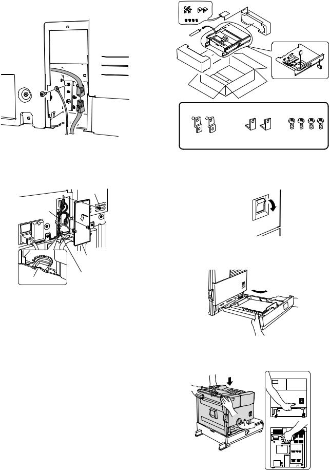
[4] UNPACKING AND INSTALLATION
1. AR-D28
<Before installation>
•Start installation after checking that the DATA and COMMUNICATION indicators on the operation panel are neither lit nor blinking.
<Parts included>
Front mounting |
Rear mounting |
Screws (M4x6): |
plates: 2 pcs. |
plates: 2 pcs. |
4 pcs. |
Left adjuster: 1 pc.
Left paper guides: 2 pcs. |
Right paper guides: 2 pcs. |
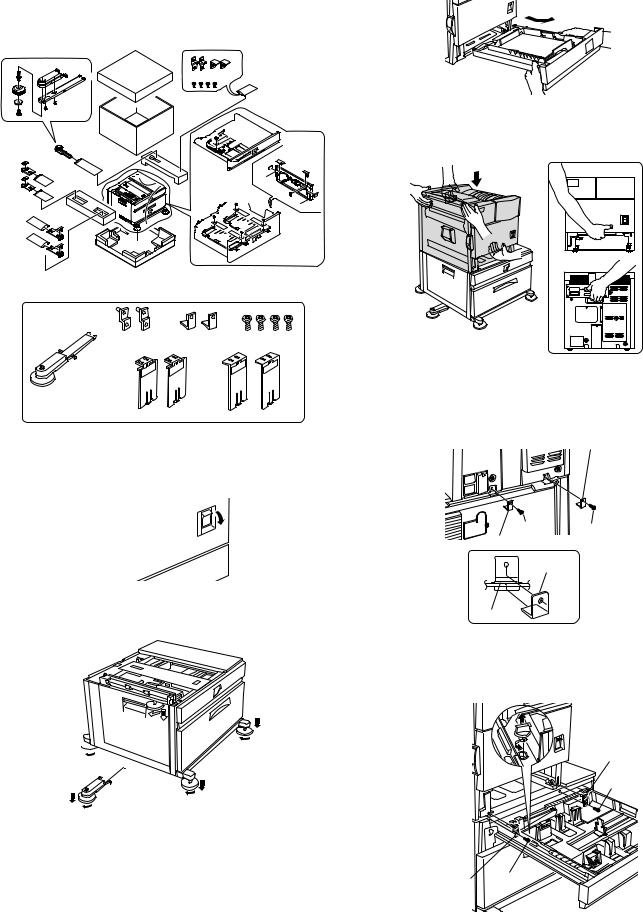
1)Turn off the main switch of the main unit of the printer.
Turn the main switch located on the front side of the printer to the "OFF" position.
Then remove the power plug from the outlet.
"OFF"
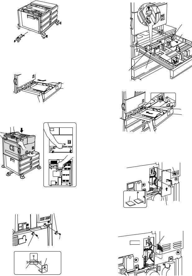
2) Attach the adjusters and adjust them.
<1>Insert the left adjusters to the stand/paper drawer.
<2>Turn the each adjusters to lower them until they touch the floor.
2

 2 2
2 2 
1 |
2 |
|
*Be sure to attach the left adjuster to prevent overturning.
Caution: The lower tray cannot be pulled out unless the adjuster is lowered to the specified position.
3) Put the main unit of the printer on the stand/paper drawer.
<1>Pull out the paper tray of the main unit until it stops and then remove it by lifting both ends of the tray.
<2>Hold the main unit of the printer at the positions shown in the illustration and put the main unit on the stand/paper drawer so that the front side and the left side of the main unit are aligned to those of the stand/paper drawer.
Front side
Rear side
Caution: For installation of the main unit, it must be held by two persons and installed without haste.
4) Connect the main unit to the stand/paper drawer.
<1>Attach the rear mounting plates using a supplied screw for each.
Rear mounting plate
Screw Screw
Rear mounting plate
Rear
mounting plate
Desk frame
Caution: Insert the rear mounting plates under the desk frame.
<2>Pull out the upper paper tray of the stand/paper drawer until it stops and attach the front mounting plates using a supplied screw for each. Then, remove the lock of the paper tray and close the tray.
Front mounting plate
Screw
Front mounting |
Screw |
|
plate |
||
|
AR-D28/D27/MU2 UNPACKING AND INSTALLATION
4 – 1
<3>Reattach the paper tray of the main unit.
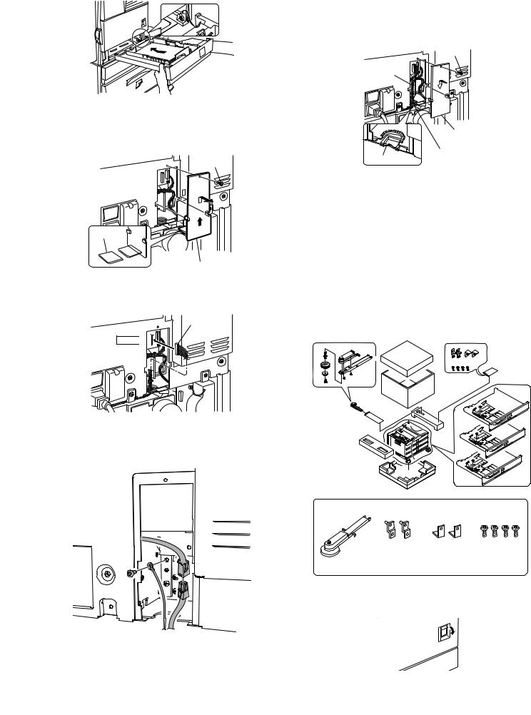
5)Connect the power supply I/F harness to the PCU PWB of the main unit of the printer.
<1>Remove the screw that fixes the harness cover of the main unit of the printer and slide the harness cover up to remove it.
Process the harness cover as shown in the illustration.
Screw
Cut out.
Harness cover
<2>Connect the power supply I/F harness connector (red, 22pin) to CN11 (red connector) of the PCU PWB of the main unit of the printer.
Connector
CN11 

Connect the connector (white, 4pin) of power supply I/F harness to the I/F connector (white, 4pin) of the main unit.
Remove the M4 screw shown in the illustration, insert the circle terminal of ground harness, and it fixes again.
<3>Reattach the power supply I/F harness cover to its original position and fix it with the removed screw.
At this time, ensure that the power supply I/F harness are arranged as shown in the illustration.
• Fix the harness securely to the wire saddle.
Screw
Power supply
I/F harness
Harness cover
Wire saddle
Wire saddle
6)Attach the paper guides to the lower tray (large capacity tray) and set the size.
Refer to "Setting and adjustment" described later.
*If another peripheral device must be installed, carry out the following step at the end of the installation work.
7)Adjust the position of the paper guides of the upper paper tray of the stand/paper drawer.
Refer to "Setting and adjustment" described later.
8)Carry out the off center adjustment.
2. AR-D27
<Before installation>
•Start installation after checking that the DATA and COMMUNICATION indicators on the operation panel are neither lit nor blinking.
<Parts included>
Front mounting |
Rear mounting |
Screws (M4x6): |
plates: 2 pcs. |
plates: 2 pcs. |
4 pcs. |
Left adjuster: 1 pc.
1)Turn off the main switch of the main unit of the printer.
Turn the main switch located on the front side of the printer to the "OFF" position.
Then remove the power plug from the outlet.
"OFF"
AR-D28/D27/MU2 UNPACKING AND INSTALLATION
4 – 2
2) Attach the adjusters and adjust them.
<1>Insert the left adjusters to the stand/paper drawer.
<2>Turn the five adjusters to lower them until they touch the floor.
<2>Pull out the upper paper tray of the stand/paper drawer until it stops and attach the front mounting plates using a supplied screw for each. Then, remove the lock of the paper tray and close the tray. Remove the locks of the middle tray and the lower tray similarly.
2
 2 2
2 2 
1 |
2 |
|
*Be sure to attach the left adjuster to prevent overturning.
Caution: The lower tray cannot be pulled out unless the adjuster is lowered to the specified position.
3) Put the main unit of the printer on the stand/paper drawer.
<1>Pull out the paper tray of the main unit until it stops and then remove it by lifting both ends of the tray.
Front mounting plate
Screw
Front mounting |
|
plate |
Screw |
<2>Hold the main unit of the printer at the positions shown in the illustration and put the main unit on the stand/paper drawer so that the front side and the left side of the main unit are aligned to those of the stand/paper drawer.
Front side
Rear side
<3>Reattach the paper tray of the main unit.
5)Connect the power supply I/F harness to the PCU PWB of the main unit of the printer.
<1>Remove the screw that fixes the harness cover of the main unit of the printer and slide the harness cover up to remove it.
Process the harness cover as shown in the illustration.
Screw
Caution: For installation of the main unit, it must be held by two persons and installed without haste.
4) Connect the main unit to the stand/paper drawer.
<1>Attach the rear mounting plates using a supplied screw for each.
Rear mounting plate
Screw Screw
Rear mounting plate
Mounting plate
Desk frame
Caution: Insert the rear mounting plates under the desk frame.
Cut out. 
Harness cover
<2>Connect the power supply I/F harness connector (red, 22pin) to CN11 (red connector) of the PCU PWB of the main unit of the printer.
Connector
CN11 

AR-D28/D27/MU2 UNPACKING AND INSTALLATION
4 – 3
Connect the connector (white, 4pin) of power supply I/F harness to |
3. AR-MU2 |
the I/F connector (white, 4pin) of the main unit. |
|
Remove the M4 screw shown in the illustration, insert the circle ter- |
|
minal of ground harness, and it fixes again. |
|
<Parts included>
<3>Reattach the harness cover to its original position and fix it with the removed screw.
At this time, ensure that the power supply I/F harness is arranged as shown in the illustration.
• Fix the harness securely to the wire saddle.
Screw
Power supply
I/F harness
Harness cover
Wire saddle
Wire saddle
6)Adjust the position of the paper guides of the upper paper tray of the stand/paper drawer.
Refer to "Setting and adjustment" described later.
7)Carry out the off center adjustment.
Front mounting plates: Rear mounting plates: Screws (M4x8): 2 pcs. 2 pcs. 4 pcs.
1)Turn off the main switch of the main unit of the printer.
Turn the main switch located on the front side of the main unit to the "OFF" position.
Then, remove the power plug of the main unit from the outlet.
"OFF"
2) Put the main unit of the printer on the multi purpose drawer.
<1>Pull out the paper tray of the main unit until it stops and then remove it by lifting both ends of the tray.
<2>Hold the main unit of the printer at the positions shown in the illustration and put the main unit on the multi purpose drawer so that the front side and the left side of the main unit are aligned to those of the multi purpose drawer.
Front side
Rear side
Caution: For installation of the main unit, it must be held by two persons and installed without haste.
AR-D28/D27/MU2 UNPACKING AND INSTALLATION
4 – 4
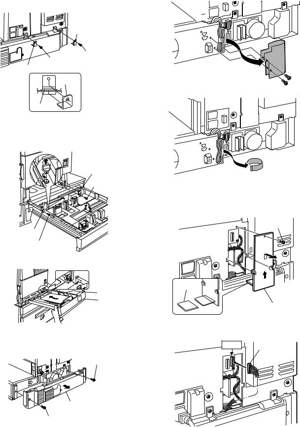
3) Connect the main unit of the printer to the multi purpose drawer.
<1>Attach the rear mounting plates using a supplied screw for each.
<2>Remove the two screws that secure the Harness protection sheet.
Rear mounting plate
Screw
Screw
Rear mounting plate
Mounting
plate
Tray frame
Caution: Insert the mounting plate under the desk frame.
<2>Pull out the paper tray of the multi purpose drawer until it stops and attach the front mounting plates using a supplied screw for each. Then, remove the lock of the paper tray and close the tray.
Front mounting plate
Screw
Front mounting plate
Screw
<3>Reattach the paper tray of the main unit of the printer.
<3> Remove the filament tape that secure the the power supply I/F harness.
5) Connect the harness to the main unit of the printer.
<1>Remove the screw that fixes the harness cover of the main unit of the printer and then slide the harness cover up to remove it. Process the harness cover as shown in the illustration.
Screw
Cut out.
Harness cover
4)Remove the multi rear cabinet.
<1>Remove the two screws that secure the multi rear cabinet.
Screw
<2>Connect the connector of the relay harness of the multi purpose drawer to the connector of the PCU PWB of the main unit of the printer.
CN10 Connector
Multi rear cabinet
Screw
AR-D28/D27/MU2 UNPACKING AND INSTALLATION
4 – 5
<3>Connect the connector (white, 4pin) of power supply I/F harness to the I/F connector (white, 4pin) of the main unit.
Connect the power supply I/F harness connector (red, 22pin) to CN11 (red connector) of the PCU PWB of the main unit of the printer.
Remove the M4 screw shown in the illustration, insert the circle terminal of ground harness, and it fixes again.
Connector
 CN11
CN11
*For installation of a finisher or a mail-bin stacker, see its installation manual.
6)Attach the harness cover.
Reattach the harness cover to its original position and fix it with the removed screw.
At this time, ensure that the power supply I/F harness is arranged as shown in the illustration.
• Fix the harness securely to the wire saddle.
Screw
Harness cover
Wire saddle
Wire saddle
*If another peripheral device must be installed, carry out the following step at the end of the installation work.
7)Adjust the position of the paper guides of the paper tray. Refer to "Setting and adjustment" described later.
8)Carry out the off center adjustment.
AR-D28/D27/MU2 UNPACKING AND INSTALLATION
4 – 6
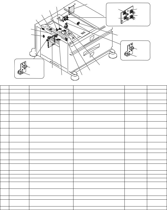
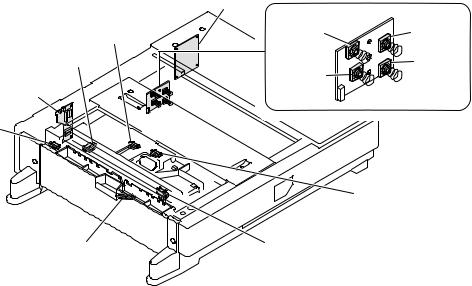
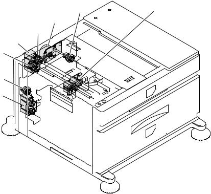
[5] EXTERNAL VIEWS AND INTERNAL STRUCTURES
A. EXTERNAL VIEW
|
|
|
|
1 |
|
5 |
|
|
2 |
|
1 |
|
|
3 |
|
|
|
|
|
5 |
4 |
|
|
|
|
|
|
5 |
1 |
|
|
|
|
|
|
|
AR-D27 |
|
|
AR-D28 |
|
|
|
AR-MU2 |
1 Multi-purpose tray (No. 2 tray) |
2 |
No. 3 tray |
|
3 No. 4 tray |
4 Large capacity tray |
5 |
Desk left door |
|
|
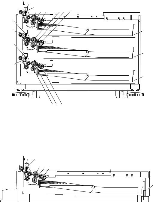
B. INTERNAL STRUCTURE
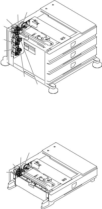
(1) AR-D28
4
1.TPFD1 |
8 |
9 |
10 |
|
|
|
|||
5 |
6 |
7 |
|
|
15
 16
16
2.TPFD2
14
|
|
3.TPFD3 |
17 |
11 |
|
18 |
|
|
13 |
12 |
|
|
|||
|
|
|
|
|
|
||
|
|
|
|
|
|
|
|
1 |
Tandem tray paper transport sensor 1 (TPFD1) |
7 |
Multipurpose tray paper take-up roller |
|
13 |
Tandem tray 1 separation roller |
|
2 |
Tandem tray paper transport sensor 2 (TPFD2) |
8 |
Tandem tray transport roller 2 |
|
14 |
Tandem tray 1 paper feed roller |
|
3 |
Tandem tray paper transport sensor 3 (TPFD3) |
9 |
Tandem tray 2 paper feed roller |
|
15 |
Tandem tray paper transport roller 1 |
|
4 |
Multipurpose tray paper transport roller |
10 |
Tandem tray 2 paper take-up roller |
|
16 |
Multipurpose tray |
|
5 |
Multipurpose tray paper feed roller |
|
11 |
Tandem tray 2 separation roller |
|
17 |
Tandem tray 1 |
6 |
Multipurpose tray separation roller |
|
12 |
Tandem tray 1 take-up roller |
|
18 |
Tandem tray 2 |
AR-D28/D27/MU2 EXTERNAL VIEWS AND INTERNAL STRUCTURES
5 – 1
(2) AR-D27
4 |
|
|
|
|
|
1.DPFD1 |
|
|
|
||
5 |
6 |
7 |
9 |
10 |
11 |
|
|
|
|||
2.DPFD2 |
|
|
|
|
|
8 |
|
|
|
|
16 |
3.DPFD3
17
15
18
|
|
|
14 |
13 |
12 |
|
|
|
|
|
|
|
|
||
1 |
Desk paper transport sensor 1 (DPFD1) |
7 |
Multipurpose tray paper take-up roller |
13 |
Desk tray 3 paper feed roller |
||
2 |
Desk paper transport sensor 2 (DPFD2) |
8 |
Desk transport roller 2 |
14 |
Desk tray 3 paper feed roller |
||
3 |
Desk paper transport sensor 3 (DPFD3) |
9 |
Desk tray 2 paper feed roller |
15 |
Desk tray 3 paper transport roller |
||
4 |
Desk paper transport roller 1 |
10 |
Desk tray 2 paper separation roller |
16 |
Multipurpose tray |
||
5 |
Multipurpose tray paper feed roller |
11 |
Desk tray 2 take-up roller |
17 |
Desk tray 2 |
||
6 |
Multipurpose tray separation roller |
12 |
Desk tray 3 take-up roller |
18 |
Desk tray 3 |
||
(3) AR-MU2
2 1.MCPPD
3 4 5
6
1 |
Multipurpose tray paper transport sensor (MCPPD) |
3 |
Multipurpose tray paper feed roller |
5 |
Multipurpose tray paper take-up roller |
2 |
Multipurpose tray paper transport roller |
4 |
Multipurpose tray separation roller |
6 |
Multipurpose tray |
AR-D28/D27/MU2 EXTERNAL VIEWS AND INTERNAL STRUCTURES
5 – 2
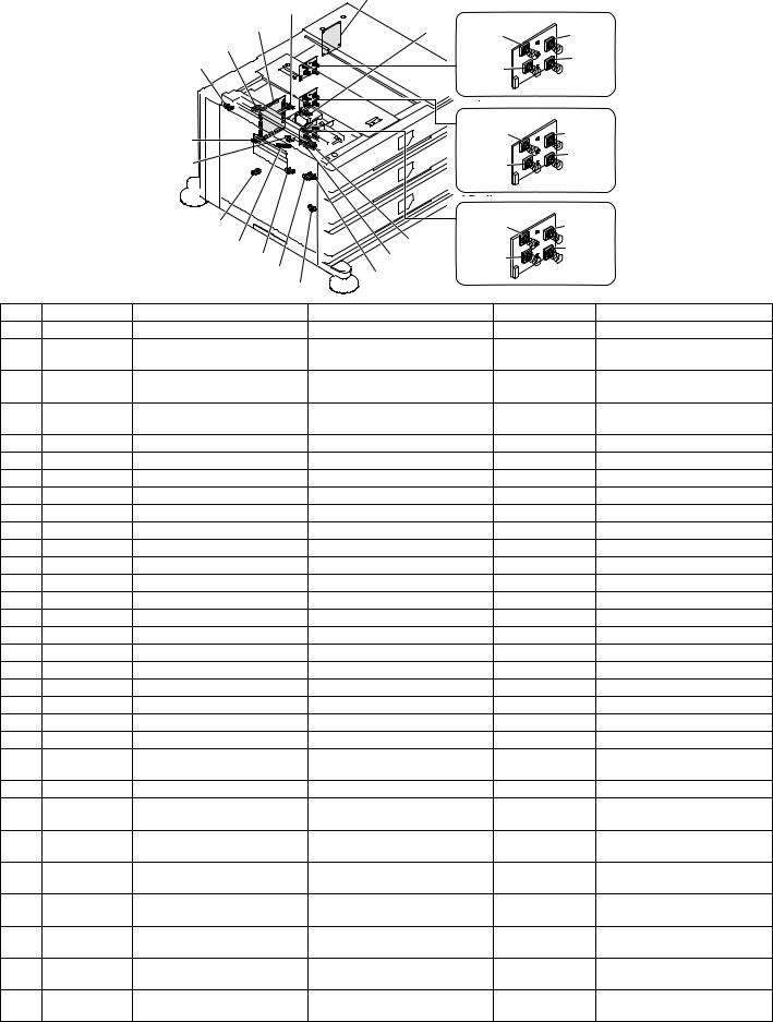
C. PWB, SENSOR
(1) AR-D28
|
|
|
21. |
|
|
|
|
6.MCLUD |
22. |
|
|
|
|
|
|
|
|
|
|
5.TPFD3 |
7.MCSS1 |
8.MCSS2 |
|
|
|
4.MCSPD |
|
10.MCSS4 |
|
|
|
3.TDRS |
|
||
|
|
9.MCSS3 |
|
|
|
|
2.TSPD1 |
|
|
|
|
|
1.TPFD2 |
11.TTSD |
|
||
|
|
|
|
||
|
|
|
|
12.TLUD2 |
|
|
|
|
|
13.TPED2 |
|
|
|
19.TLUD1 |
14.TSPD2 |
|
|
|
|
|
|
|
|
|
|
18. |
15.MCPED |
|
|
|
|
|
|
|
|
|
|
20.TPED1 |
16.TPFD1 |
|
|
|
|
17.MCPWS |
|
|
|
|
Code |
Name |
Function |
Active condition |
Remark |
1 |
TPFD2 |
Tandem tray paper transport sensor 2 |
Tandem tray paper transport detection |
L : Paper detected |
|
2 |
TSPD1 |
Tandem 1 tray |
Tandem 1 tray |
|
|
|
|
remaining paper quantity sensor |
remaining paper quantity detection |
|
|
3 |
TDRS |
Side door open/close sensor |
Side door open/close detection |
H : Door closed |
|
4 |
MCSPD |
MP tray remaining paper quantity |
MP tray remaining paper quantity detection |
|
|
|
|
sensor |
|
|
|
5 |
TPFD3 |
Tandem tray paper transport sensor 3 |
Tandem tray paper transport detection |
L : Paper detected |
|
6 |
MCLUD |
MP tray upper limit sensor |
MP tray upper limit detection |
H : Upper limit |
|
|
|
|
|
detected |
|
7 |
MCSS1 |
MP tray rear edge sensor 1 |
MP tray rear edge size detection |
L : When pressed |
In MP tray rear |
|
|
|
|
|
edge size PWB |
8 |
MCSS2 |
MP tray rear edge sensor 2 |
MP tray rear edge size detection |
L : When pressed |
In MP tray rear |
|
|
|
|
|
edge size PWB |
9 |
MCSS3 |
MP tray rear edge sensor 3 |
MP tray rear edge size detection |
L : When pressed |
In MP tray rear |
|
|
|
|
|
edge size PWB |
10 |
MCSS4 |
MP tray rear edge sensor 4 |
MP tray rear edge size detection |
L : When pressed |
In MP tray rear |
|
|
|
|
|
edge size PWB |
11 |
TTSD |
Tandem tray open/close sensor |
Tandem tray open/close detection |
H : Tray closed |
|
12 |
TLLD2 |
Tandem 2 tray upper limit sensor |
Tandem tray 2 upper limit detection |
L : Upper limit |
|
|
|
|
|
detected |
|
13 |
TPED2 |
Tandem 2 tray paper empty sensor |
Tandem tray 2 paper empty detection |
H : Paper loaded |
|
14 |
TSPD2 |
Tandem 2 tray |
Tandem 2 tray |
|
|
|
|
remaining paper quantity sensor |
remaining paper quantity detection |
|
|
15 |
MCPED |
MP tray paper empty sensor |
MP tray paper empty detection |
L : Paper loaded |
|
16 |
TPFD1 |
Tandem tray paper transport sensor 1 |
Tandem tray paper transport detection |
L : Paper detected |
|
17 |
MCPWS |
MP tray width sensor |
MP tray paper width detection |
|
Slide volume |
18 |
Control PWB |
Control PWB |
Communication with the machine, |
|
|
|
|
|
machine operation control |
|
|
19 |
TLLD1 |
Tandem 1 tray upper limit sensor |
Tandem tray 1 upper limit detection |
L : Upper limit |
|
|
|
|
|
detected |
|
20 |
TPED1 |
Tandem 1 tray paper empty sensor |
Tandem tray 1 paper empty detection |
H : Paper loaded |
|
21 |
MP tray rear |
MP tray rear edge size PWB |
Multi-purpose tray rear edge size detection |
|
|
|
edge size PWB |
|
|
|
|
22 |
Power I/F PWB |
Power I/F PWB |
Distributed the power supply from the main unit. |
|
|
AR-D28/D27/MU2 EXTERNAL VIEWS AND INTERNAL STRUCTURES
5 – 3
(2) AR-D27
|
|
|
31. |
|
|
|
|
|
|
4.MCLUD |
|
28. |
|
|
|
|
|
3. |
5.MCPED |
|
|
|
|
|
|
|
|
6.MCSS1 |
7.MCSS2 |
||
|
|
2.MCSPD |
|
|
|
|
|
|
|
1.DDRS |
|
8.MCSS3 |
9.MCSS4 |
||
|
|
|
|
|
|||
|
|
|
|
|
|
||
|
|
|
|
29. |
|
|
|
|
|
27.DSPD1 |
|
10.DCSS11 |
11.DCSS12 |
||
|
|
|
|
|
|
|
|
|
|
26.DLUD1 |
|
|
|
13.DCSS14 |
|
|
|
|
12.DCSS13 |
|
|
||
|
|
|
|
30. |
|
|
|
|
|
25.DSPD2 |
|
14.DCSS21 |
15.DCSS22 |
||
|
|
24.MCPWS |
18.DPFD1 |
|
|
17.DCSS24 |
|
|
|
|
|
|
|
||
|
|
23.DLUD2 |
19.DPED1 |
16.DCSS23 |
|
|
|
|
|
22.DPED2 |
20.DPFD2 |
|
|
|
|
|
|
|
|
|
|
|
|
|
|
21.DPFD3 |
|
|
|
|
|
|
Code |
Name |
Function |
|
Active condition |
Remark |
|
1 |
DDRS |
Side door open/close sensor |
Side door open/close detection |
H : Door closed |
|
||
2 |
MCSPD |
MP tray |
MP tray |
|
|
|
|
|
|
remaining paper quantity sensor |
remaining paper quantity detection |
|
|
|
|
3 |
Control PWB |
Control PWB |
Communication with the machine, |
|
|
|
|
|
|
|
machine operation control |
|
|
|
|
4 |
MCLUD |
MP tray upper limit sensor |
MP tray upper limit detection |
|
H : Upper limit |
|
|
|
|
|
|
|
detected |
|
|
5 |
MCPED |
MP tray paper empty sensor |
MP tray paper empty detection |
L : Paper loaded |
|
||
6 |
MDSS1 |
MP tray rear edge sensor 1 |
MP tray rear edge size detection |
L : When pressed |
In MP tray rear edge size PWB |
||
7 |
MCSS2 |
MP tray rear edge sensor 2 |
MP tray rear edge size detection |
L : When pressed |
In MP tray rear edge size PWB |
||
8 |
MCSS3 |
MP tray rear edge sensor 3 |
MP tray rear edge size detection |
L : When pressed |
In MP tray rear edge size PWB |
||
9 |
MCSS4 |
MP tray rear edge sensor 4 |
MP tray rear edge size detection |
L : When pressed |
In MP tray rear edge size PWB |
||
10 |
DCSS11 |
No. 3 tray rear edge sensor 1 |
No. 3 tray rear edge size detection |
L : When pressed |
In No. 3 tray rear edge size PWB |
||
11 |
DCSS12 |
No. 3 tray rear edge sensor 2 |
No. 3 tray rear edge size detection |
L : When pressed |
In No. 3 tray rear edge size PWB |
||
12 |
DCSS13 |
No. 3 tray rear edge sensor 3 |
No. 3 tray rear edge size detection |
L : When pressed |
In No. 3 tray rear edge size PWB |
||
13 |
DCSS14 |
No. 3 tray rear edge sensor 4 |
No. 3 tray rear edge size detection |
L : When pressed |
In No. 3 tray rear edge size PWB |
||
14 |
DCSS21 |
No. 4 tray rear edge sensor 1 |
No. 4 tray rear edge size detection |
L : When pressed |
In No. 4 tray rear edge size PWB |
||
15 |
DCSS22 |
No. 4 tray rear edge sensor 2 |
No. 4 tray rear edge size detection |
L : When pressed |
In No. 4 tray rear edge size PWB |
||
16 |
DCSS23 |
No. 4 tray rear edge sensor 3 |
No. 4 tray rear edge size detection |
L : When pressed |
In No. 4 tray rear edge size PWB |
||
17 |
DCSS24 |
No. 4 tray rear edge sensor 4 |
No. 4 tray rear edge size detection |
L : When pressed |
In No. 4 tray rear edge size PWB |
||
18 |
DPFD1 |
Desk paper transport sensor 1 |
Desk paper transport detection |
L : Paper detected |
|
||
19 |
DPED1 |
N. 3 tray paper empty sensor |
N. 3 tray paper empty detection |
L : Paper loaded |
|
||
20 |
DPFD2 |
Desk paper transport sensor 2 |
Desk paper transport detection |
L : Paper detected |
|
||
21 |
DPFD3 |
Desk paper transport sensor 3 |
Desk paper transport detection |
L : Paper detected |
|
||
22 |
DPED2 |
No. 4 tray paper empty sensor |
No. 4 tray paper empty detection |
L : Paper loaded |
|
||
23 |
DLUD2 |
No. 4 tray upper limit sensor |
No. 4 tray upper limit detection |
H : Upper limit |
|
||
|
|
|
|
|
detected |
|
|
24 |
MCPWS |
MP tray width sensor |
MP tray paper width detection |
Analog voltage |
Slide volume |
||
25 |
DSPD2 |
No. 4 tray |
No. 4 tray |
|
|
|
|
|
|
remaining paper quantity sensor |
remaining paper quantity detection |
|
|
|
|
26 |
DLUD1 |
No. 3 tray upper limit sensor |
No. 3 tray upper limit detection |
H : Upper limit |
|
||
|
|
|
|
|
detected |
|
|
27 |
DSPD1 |
No. 3 tray |
No. 3 tray |
|
|
|
|
|
|
remaining paper quantity sensor |
remaining paper quantity detection |
|
|
|
|
28 |
MP tray rear |
MP tray rear edge size PWB |
MP tray rear edge size detection |
|
|
|
|
|
edge size PWB |
|
|
|
|
|
|
29 |
No. 3 tray rear |
No. 3 tray rear edge size PWB |
No. 3 tray rear edge size detection |
|
|
|
|
|
edge size PWB |
|
|
|
|
|
|
30 |
No. 4 tray rear |
No. 4 tray rear edge size PWB |
No. 4 tray rear edge size detection |
|
|
|
|
|
edge size PWB |
|
|
|
|
|
|
31 |
Power I/F PWB |
Power I/F PWB |
Distributed the power supply from |
|
|
|
|
|
|
|
the main unit. |
|
|
|
|
|
|
AR-D28/D27/MU2 EXTERNAL VIEWS AND INTERNAL STRUCTURES |
|
|
|||
5 – 4
(3) AR-MU2
12.
|
13. |
|
4.MCLUD |
5.MCSS1 |
6.MCSS2 |
|
|
|
3.MCSPD |
|
8.MCSS4 |
|
7.MCSS3 |
|
2.
1.MCDRS
9.MCPED
11.MCPWS |
10.MCPPD |
|
|
Code |
Name |
Function |
Active condition |
Remark |
|
|
|
|
|
|
1 |
MCDRS |
MP door open / close |
MP left door open / close detection |
H : Door closed |
|
|
|
sensor |
|
|
|
|
|
|
|
|
|
2 |
Control PWB |
Control PWB |
Communication with the machine, |
|
|
|
|
|
machine operation control |
|
|
|
|
|
|
|
|
3 |
MCSPD |
MP tray remaining paper |
MP tray remaining paper quantity detection |
L : When |
|
|
|
quantity sensor |
|
pressed |
|
|
|
|
|
|
|
4 |
MCLUD |
MP tray upper limit sensor |
MP tray upper limit detection |
H : Upper limit |
|
|
|
|
|
detected |
|
|
|
|
|
|
|
5 |
MDSS1 |
MP tray rear edge sensor 1 |
MP tray rear edge size detection |
L : When |
In MP tray rear edge size PWB |
|
|
|
|
pressed |
|
|
|
|
|
|
|
6 |
MCSS2 |
MP tray rear edge sensor 2 |
MP tray rear edge size detection |
L : When |
In MP tray rear edge size PWB |
|
|
|
|
pressed |
|
|
|
|
|
|
|
7 |
MCSS3 |
MP tray rear edge sensor 3 |
MP tray rear edge size detection |
L : When |
In MP tray rear edge size PWB |
|
|
|
|
pressed |
|
|
|
|
|
|
|
8 |
MCSS4 |
MP tray rear edge sensor 4 |
MP tray rear edge size detection |
L : When |
In MP tray rear edge size PWB |
|
|
|
|
pressed |
|
|
|
|
|
|
|
9 |
MCPED |
MP tray paper empty |
MP tray paper empty detection |
L : Paper loaded |
|
|
|
sensor |
|
|
|
|
|
|
|
|
|
10 |
MCPPD |
MP transport sensor |
Detection of paper on the path |
L : Paper |
|
|
|
|
|
detected |
|
|
|
|
|
|
|
11 |
MCPWS |
MP tray width sensor |
MP tray paper width detection |
Analog voltage |
Slide volume |
|
|
|
|
|
|
12 |
MP tray rear |
MP tray rear |
MP tray rear edge size detection |
|
|
|
edge size PWB |
edge size PWB |
|
|
|
|
|
|
|
|
|
13 |
Power I/F PWB |
Power I/F PWB |
Distributed the power supply from the main unit. |
|
|
|
|
|
|
|
|
AR-D28/D27/MU2 EXTERNAL VIEWS AND INTERNAL STRUCTURES
5 – 5
D. MOTOR, CLUTCH
(1) AR-D28
7.TPCL2 |
8.TLUM2 |
6.TMM
5.MCPCL
4.MCLUM
3.TPFCL
2.TPCL1
1.TLUM1
|
Code |
Name |
Function |
Remark |
|
|
|
|
|
1 |
TLUM1 |
Tandem tray 1 lift-up motor |
Tandem tray 1 lift-up |
|
|
|
|
|
|
2 |
TPCL1 |
Tandem tray 1 paper feed clutch |
Clutch for paper feed from tandem tray 1 |
|
|
|
|
|
|
3 |
TPFCL |
LCC transport clutch |
Clutch for transport from LCC desk |
|
|
|
|
|
|
4 |
MCLUM |
Multi-purpose tray lift-up motor |
Multi-purpose tray lift-up |
|
|
|
|
|
|
5 |
MCPCL |
Multi-purpose paper feed clutch |
Clutch for paper feed from Multi-purpose tray |
|
|
|
|
|
|
6 |
TMM |
LCC transport motor |
LCC desk paper transport |
|
|
|
|
|
|
7 |
TPCL2 |
Tandem tray 2 paper feed clutch |
Clutch for paper feed from tandem tray 2 |
|
|
|
|
|
|
8 |
TLUM2 |
Tandem tray 2 lift-up motor |
Tandem tray 2 lift-up |
|
|
|
|
|
|
AR-D28/D27/MU2 EXTERNAL VIEWS AND INTERNAL STRUCTURES
5 – 6
(2) AR-D27
6.DMM
5.MCPCL
4.MCLUM
3.DPFCL
2.DLUM1
1.DLUM2
8.DPCL2
7.DPCL1
|
Code |
Name |
Function |
Remark |
|
|
|
|
|
1 |
DLUM2 |
Desk 2 tray lift-up motor |
Gate switch between duplex and paper exit |
|
|
|
|
|
|
2 |
DLUM1 |
Desk 1 tray lift-up motor |
Cooling the machine and inside of ADU |
|
|
|
|
|
|
3 |
DPFCL |
Desk transport clutch |
Clutch for transport |
|
|
|
|
|
|
4 |
MCLUM |
Multi-purpose tray lift-up motor |
Multi-purpose tray lift-up |
|
|
|
|
|
|
5 |
MCPCL |
Multi-purpose paper feed clutch |
Clutch for paper feed from Multi-purpose tray |
|
|
|
|
|
|
6 |
DMM |
3 tray desk transport motor |
No. 3 tray desk paper transport |
|
|
|
|
|
|
7 |
DPCL1 |
Desk 1 tray paper feed clutch |
Clutch for paper feed from desk tray 1 |
|
|
|
|
|
|
8 |
DPCL 2 |
Desk 2 tray paper feed clutch |
Clutch for paper feed from desk tray 2 |
|
|
|
|
|
|
(3) AR-MU2
4.MCM
3.MCPCL
2.MCLUM
1.MCFCL
|
Code |
Name |
Function |
Remark |
|
|
|
|
|
1 |
MCFCL |
Multi-purpose tray transport clutch |
Multi-purpose tray transport clutch |
|
|
|
|
|
|
2 |
MCLUM |
Multi-purpose tray lift-up motor |
Multi-purpose tray lift-up |
|
|
|
|
|
|
3 |
MCPCL |
Multi-purpose paper feed clutch |
Clutch for paper feed from Multi-purpose tray |
|
|
|
|
|
|
4 |
MCM |
Multi-purpose tray transport motor |
Multi-purpose tray paper transport |
|
|
|
|
|
|
AR-D28/D27/MU2 EXTERNAL VIEWS AND INTERNAL STRUCTURES
5 – 7
[6] ADJUSTMENTS
1. CHANGING THE PAPER SIZE
[Upper tray(Tray2)]
•A3 to A5R(11x7 to 5-1/2x8-1/2R) size plain paper can be set.
•Special paper can be set.
•Two maximum height lines are indicated: one for plain paper and one for special paper.
[Middle/Lower tray(Tray3/4)]
• A4, B5 or 8-1/2" x 11" size plain paper can be set.
Use the following procedure to change the size as needed.
1)Pull out paper tray.
If paper remains in the tray, remove it.
2)Adjust the guide plates A and B in the tray to the length and width of the paper.
The guide plates A and B are slidable. Adjust them to the paper size to be loaded while squeezing their lock levers.
3)Load paper into the tray.
Do not exceed red line when loading special paper to upper tray.
4)Gently push tray into the machine.
Push the tray firmly all the way into the machine.
5)Set the paper size.
Be sure to set the paper size and paper type referring to "2.Setting the paper type and paper size".
If this is not done, paper misfeeds will occur.
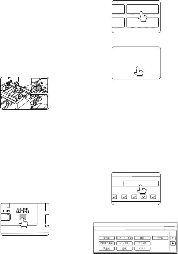
2.SETTING THE PAPER TYPE AND PAPER SIZE
Follow these steps to change the paper type setting if the paper type is changed in either paper tray. For the paper types that can be used in each tray.
1)Press the [CUSTOM SETTINGS] key.
The custom setting menu screen will appear.
2)Touch the [PAPER TRAY SETTINGS] key. The paper tray selection screen will appear.
RINT
PAPER TRAY
SETTINGS
TA |
PRINTER |
ORWARD |
CONDITION |
3) Touch the [TRAY SETTINGS] key.
CUSTOM SETTINGS
PAPER TRAY SETTINGS
TRAY SETTINGS
4) Display the setting screen of the desired paper tray.
CUSTOM SETTINGS
PAPER TRAY SETTINGS |
|
OK |
|
|
|
TYPE / SIZE
FIXED PAPER SIDE 1/4
TRAY 1 |
PLAIN / A4 |
DISABLE DUPLEX
COPY |
FAX |
I-FAX |
DOC. |
DISABLE STAPLE |
||
FILING |
||||||
|
|
|
|
|
DISABLE PUNCH
Touch the  key or
  key to display the setting screen of the desired paper tray.
Note: To automatically switch to a tray with the same size and type of paper (if there is one) in the event that the paper tray runs out of paper, display the last screen with the  key and select [AUTO TRAY SWITCHING].
5) Touch the [TYPE/SIZE] key.
PER TRAY SETTINGS
TYPE / SIZE
TRAY 2 |
PLAIN / A4 |
DOC.
PRINT COPY FAX I-FAX FILING
6)Select the type of paper that was loaded in the tray. Example: The paper type of tray 2 is selected
CUSTOM SETTINGS
TRAY 2 TYPE/SIZE SETTING |
CANCEL |
SELECT THE PAPER TYPE.
1/2
PLAIN |
|
|
LETTER HEAD |
|
|
HEAVY PAPER |
|
ENVELOPE |
|
|
|
|
|
|
|
|
|
PRE-PRINTED |
|
|
PRE-PUNCHED |
|
|
LABELS |
|
|
|
|
|
|
|
|
|
|
|
RECYCLED |
|
|
COLOUR |
|
|
TRANSPARENCY |
|
|
1/2
Touch the desired paper type to select it.
The paper size setting screen will appear.
Note: Heavy paper, label sheets and transparency film cannot be used in trays 1, 3, and 4. Envelopes can only be placed in tray 2.
AR-D28/D27/MU2 ADJUSTMENTS
6 – 1

[7] DISASSEMBLY AND ASSEMBLY, MAINTENANCE
(1) AR-D28
A. MAJOR PARTS AND SIGNAL FUNCTIONS
|
|
|
|
|
|
|
|
2 |
MCLUM/ |
|
|
|
|
|
|
|
|
|
|
|
1 |
+24V |
|
|
|
|
|
|
|
|
|
|
|
PHR-2 |
|
|
|
|
|
|
|
|
|
|
|
|
2 |
2 |
|
|
|
|
|
|
|
|
|
|
|
1 |
1 |
|
|
|
|
|
|
|
|
|
|
SMP-02V-NC SMR-02V-N |
|
|
|
||
|
|
|
|
|
|
|
|
2 |
2 |
|
|
|
|
|
|
|
|
|
|
|
1 |
1 |
|
|
|
|
|
|
|
|
|
|
SMP-02V-BC SMR-02V-B |
|
|
|
||
|
|
|
|
|
|
|
MCLUM |
TMM |
MPT LD PWB |
|
||
|
|
|
|
|
|
|
|
|
|
|
||
|
|
|
|
|
|
|
|
|
MCPCL |
MCSS1 |
MCSS2 |
|
|
|
|
|
|
|
|
|
|
|
|
||
|
|
|
|
|
|
|
|
|
|
|
|
|
|
|
|
|
|
|
|
|
|
|
MCSS3 |
MCSS4 |
|
|
|
|
|
|
|
|
|
TPFCL |
|
|
|
|
|
|
|
|
|
11 |
11 |
|
|
|
|
|
|
|
|
|
|
|
10 |
10 |
|
|
|
MCSPD |
|
|
TAN Control PWB |
|
|
9 |
9 |
|
|
|
|
|
|||
|
|
8 |
8 |
|
|
|
MCLUD |
|
||||
|
|
|
|
|
7 |
7 |
|
|
|
|
|
|
CN-D |
|
|
|
|
6 |
6 |
5 |
TMMCLK/ |
|
|
MCPED |
|
|
|
|
|
5 |
5 |
|
|
|
||||
VB(+24V) |
|
1 |
|
|
4 |
4 |
4 |
TMM-T |
|
|
|
|
TPFCL/ |
|
2 |
|
|
3 |
3 |
3 |
TMM/ |
TDRS |
|
|
|
VB(+24V) |
|
3 |
|
|
|
|
|
|||||
MCPCL/ |
|
4 |
|
|
2 |
2 |
2 |
GND1 |
|
|
|
|
|
|
|
1 |
1 |
1 |
+24V |
|
|
|
|
||
+24V(MCLUM) |
|
5 |
|
|
|
|
|
|
||||
|
|
SMP-11V-NC |
SMR-11V-N |
PHR-5 |
|
|
|
|
||||
MCLUM/ |
|
6 |
|
|
|
|
|
|||||
|
|
|
|
|
|
|
|
|
|
|
||
VB(+24V) |
|
7 |
|
|
|
|
1 |
+5V |
|
|
|
|
GND1(P-GND) |
|
8 |
|
|
|
|
2 |
MCSPD |
|
|
|
|
TMM/ |
|
9 |
|
|
|
|
3 |
GND2 |
|
|
TPFD1 |
|
TMMCLK/ |
|
10 |
|
|
|
|
179228-3 |
|
|
|
||
TMM-T |
|
11 |
|
|
|
|
1 |
N.C. |
|
MCPWS |
|
|
MCSPD |
|
12 |
|
|
|
|
|
|
|
|||
VD(+5V) |
|
13 |
|
|
|
|
2 |
GND2 |
|
|
|
|
GND2(S-GND) |
|
14 |
|
|
|
|
3 |
MCSS1 |
|
|
|
|
MCSS1 |
|
15 |
|
|
|
|
4 |
MCSS2 |
|
|
|
|
GND2(S-GND) |
|
16 |
|
|
|
|
5 |
MCSS3 |
|
|
|
|
MCSS2 |
|
17 |
|
|
|
|
6 |
MCSS4 |
|
|
|
|
MCSS3 |
|
18 |
|
|
|
|
PHR-6 |
|
|
|
|
|
MCSS4 |
|
19 |
|
|
|
|
|
|
|
TPFD3 |
|
|
F-GND |
|
20 |
|
|
|
|
|
|
|
|
|
|
PHDR-20VS-1 |
|
|
|
18 |
18 |
|
1 |
+5V |
|
|
|
|
|
|
|
SRA-21T-4 |
|
|
|
|
|
||||
|
|
|
17 |
17 |
|
2 |
MCLUD |
|
|
|
|
|
CN-E |
|
|
|
16 |
16 |
|
3 |
GND2 |
TPFD2 |
|
|
|
|
|
|
|
|
|
179228-3 |
|
|
|
|||
GND2(S-GND) |
|
1 |
|
|
|
|
1 |
+5V |
|
|
|
|
MCLUD |
|
2 |
|
15 |
15 |
|
|
|
|
|
||
VD(+5V) |
|
3 |
|
14 |
14 |
|
2 |
TPFD1 |
|
|
|
|
VD(+5V) |
|
4 |
|
13 |
13 |
|
3 |
GND2 |
|
|
|
|
GND2(S-GND) |
|
5 |
|
|
|
|
179228-3 |
|
|
|
|
|
MCPED |
|
6 |
|
9 |
9 |
|
1 |
+5V |
|
|
|
|
GND2(S-GND) |
|
7 |
|
|
|
|
|
|
||||
|
|
8 |
8 |
|
2 |
TDRS |
|
|
|
|
||
TDRS |
|
8 |
|
7 |
7 |
|
3 |
GND2 |
|
|
|
|
VD(+5V) |
|
9 |
|
|
|
|
|
|
||||
|
|
|
|
|
179228-3 |
|
|
|
|
|||
VD(+5V) |
|
10 |
|
|
|
|
|
|
|
|
||
|
|
6 |
6 |
|
1 |
+5V |
|
|
|
|
||
GND2(S-GND) |
|
11 |
|
|
|
|
|
|
||||
TPFD1 |
|
12 |
|
5 |
5 |
|
2 |
MCPED |
|
|
|
|
MCPWS2 |
|
13 |
|
4 |
4 |
|
3 |
GND2 |
|
|
|
|
MCPWS |
|
14 |
SMP-18V-BC |
SMR-18V-B |
179228-3 |
|
|
|
|
|||
VD(+5V) |
|
15 |
|
3 |
3 |
|
2T MCPWS |
|
|
|
|
|
N.C. |
|
16 |
|
|
|
|
|
|
||||
|
|
2 |
2 |
|
1T MCPWS2 |
|
|
|
|
|||
PHDR-16VS-1 |
|
|
|
|
|
|
|
|
||||
|
|
|
1 |
1 |
|
3T VAREF |
|
|
|
|
||
|
|
|
|
|
|
|
|
|
||||
CN-I |
|
|
SMP-03V-BC |
SMR-03V-B |
|
|
|
|
|
|
||
|
|
|
|
|
|
|
|
|
|
|
|
|
S-GND |
|
1 |
1 |
VD(+5V) |
|
|
|
|
|
|
|
|
TPFD3 |
|
2 |
2 |
TPFD3 |
|
|
|
|
|
|
|
|
VD(+5V) |
|
3 |
3 |
S-GND |
|
|
|
|
|
TPCL2 |
|
|
S-GND |
|
4 |
179228-3 |
|
|
|
|
|
|
|
||
TLUD1 |
|
5 |
1 |
TPED1 |
|
|
|
|
|
|
|
|
VD(+5VR) |
|
6 |
|
|
|
|
|
|
|
|
||
N.C |
|
7 |
2 |
TLUD1 |
|
|
|
|
|
TAN Sensor PWB |
|
|
TPED1 |
|
8 |
3 |
S-GND |
|
|
|
|
|
|
||
VD(+5V) |
|
9 |
4 |
VD(+5VR) |
|
|
|
|
|
|
|
|
PHR-9 |
|
|
5 |
VD(+5V) |
|
|
|
|
|
|
TLUD2 |
TTSD |
|
|
PHR-5 |
|
|
|
|
|
|
||||
CN-B |
|
|
|
|
|
|
|
TPED2 |
|
|||
|
|
1 |
VD(+5V) |
|
|
|
|
|
|
|
||
S-GND |
|
1 |
|
|
|
|
|
|
|
|||
TSPD1 |
|
2 |
2 |
TSPD1 |
|
|
|
|
|
|
|
|
VD(+5V) |
|
3 |
3 |
S-GND |
|
|
|
|
|
|
|
|
TLUM2/ |
|
4 |
179228-3 |
|
|
|
|
|
|
|
|
|
VB(TLUM2) |
|
5 |
1 |
VB(+24V) |
|
|
|
|
|
TSPD2 |
|
|
N.C. |
|
6 |
|
|
|
TLUM2 |
|
|||||
S-GND |
|
7 |
2 |
TLUM2 |
|
|
|
|
|
|
||
TPFD2 |
|
8 |
PHR-2 |
|
|
|
|
|
|
|
|
|
VD(+5V) |
|
9 |
1 |
VD(+5V) |
|
|
|
TPCL1 |
|
|
|
|
S-GND |
|
10 |
|
|
|
|
|
|
||||
TTSD |
|
11 |
2 |
TPFD2 |
|
|
|
|
|
|
|
|
|
3 |
S-GND |
|
|
|
|
|
|
|
|
||
VD(+5V) |
|
12 |
|
|
|
|
|
|
|
|
||
|
179228-3 |
|
|
|
|
TAN Sensor PWB |
|
|
||||
PHR-12 |
|
|
|
|
|
|
|
|
||||
|
|
1 |
VD(+5V) |
|
|
|
|
|
|
|||
|
|
|
|
|
|
|
|
|
|
|
||
|
|
|
2 |
TTSD |
|
|
|
|
|
TLUD1 |
|
|
|
|
|
3 |
S-GND |
|
|
|
|
|
|
|
|
CN-C |
|
|
179228-3 |
|
|
|
|
TPED1 |
TSPD1 |
|
|
|
|
|
|
|
|
|
|
|
|
|
|||
VB(+24V) |
|
1 |
1 |
1 |
|
|
|
|
|
|
|
|
TPCL1/ |
|
2 |
2 |
2 |
|
|
|
|
|
|
|
|
PHR-2 |
|
|
SMP-02V-BC SMR-02V-B |
|
|
|
|
|
|
|
||
CN-G |
(RED) |
|
|
|
|
|
|
|
|
|
|
|
VB(+24V) |
|
1 |
1 |
1 |
|
|
TLUM1 |
|
|
|
|
|
TPCL2/ |
|
2 |
2 |
2 |
|
|
|
|
|
|
||
PHR-2-R(RED) |
|
SMP-02V-NC |
SMR-02V-N |
|
|
|
|
|
|
|
||
CN-J |
|
|
1 |
VB(+24V) |
|
|
|
|
|
|
|
|
TLUM1/ |
|
1 |
|
|
|
|
|
|
|
|
||
VB(TLUM1) |
|
2 |
2 |
TLUM1/ |
|
|
|
|
|
|
|
|
N.C. |
|
3 |
PHR-2 |
|
|
|
|
|
|
|
|
|
N.C. |
|
4 |
|
|
|
|
|
|
|
|
|
|
N.C. |
|
5 |
|
|
|
|
|
|
|
|
|
|
N.C. |
|
6 |
|
|
|
|
|
|
|
|
|
|
N.C. |
|
7 |
|
|
|
|
|
|
|
|
|
|
N.C. |
|
8 |
|
|
|
|
|
|
|
|
|
|
N.C. |
|
9 |
|
|
|
|
|
|
|
|
|
|
N.C. |
|
10 |
|
|
|
|
|
|
|
|
|
|
PHR-10 |
|
|
|
|
|
|
|
|
|
|
|
|
CN-A |
|
|
1 |
VD(+5V) |
|
|
|
|
|
|
|
|
S-GND |
|
1 |
|
|
|
|
|
|
|
|
||
TSPD2 |
|
2 |
2 |
TSPD2 |
|
|
|
|
|
|
|
|
VD(+5V) |
|
3 |
3 |
S-GND |
|
|
|
|
|
|
|
|
S-GND |
|
4 |
179228-3 |
|
|
|
|
|
|
|
|
|
TLUD2 |
|
5 |
|
|
|
|
|
|
|
|
||
|
1 |
TPED2 |
|
|
|
|
|
|
|
|
||
VD(+5VR) |
|
6 |
|
|
|
|
|
|
|
|
||
N.C |
|
7 |
2 |
TLUD2 |
|
|
|
|
|
|
|
|
TPED2 |
|
8 |
3 |
S-GND |
|
|
|
|
|
|
|
|
VD(+5V) |
|
9 |
4 |
VD(+5VR) |
|
|
|
|
|
|
|
|
PHR-9 |
|
|
5 |
VD(+5V) |
|
|
|
|
|
|
|
|
|
|
|
PHR-5 |
|
|
|
|
|
|
|
|
|
AR-D28/D27/MU2 DISASSEMBLY AND ASSEMBLY, MAINTENANCE
7 – 1
Code |
Name |
Function |
Remark |
|
|
|
|
TPFD2 |
Tandem tray paper transport sensor 2 |
Tandem tray paper transport detection |
|
|
|
|
|
TSPD1 |
Tandem 1 tray remaining paper quantity sensor |
Tandem 1 tray remaining paper quantity detection |
|
|
|
|
|
TDRS |
Side door open/close sensor |
Side door open/close detection |
|
|
|
|
|
MCSPD |
MP tray remaining paper quantity sensor |
MP tray remaining paper quantity detection |
|
|
|
|
|
TPFD3 |
Tandem tray paper transport sensor 3 |
Tandem tray paper transport detection |
|
|
|
|
|
MCLUD |
MP tray upper limit sensor |
MP tray upper limit detection |
|
|
|
|
|
MCSS1 |
MP tray rear edge sensor 1 |
MP tray rear edge size detection |
In MP tray rear edge size PWB |
|
|
|
|
MCSS2 |
MP tray rear edge sensor 2 |
MP tray rear edge size detection |
In MP tray rear edge size PWB |
|
|
|
|
MCSS3 |
MP tray rear edge sensor 3 |
MP tray rear edge size detection |
In MP tray rear edge size PWB |
|
|
|
|
MCSS4 |
MP tray rear edge sensor 4 |
MP tray rear edge size detection |
In MP tray rear edge size PWB |
|
|
|
|
TTSD |
Tandem tray open/close sensor |
Tandem tray open/close detection |
|
|
|
|
|
TLLD2 |
Tandem 2 tray upper limit sensor |
Tandem tray 2 upper limit detection |
|
|
|
|
|
TPED2 |
Tandem 2 tray paper empty sensor |
Tandem tray 2 paper empty detection |
|
|
|
|
|
TSPD2 |
Tandem 2 tray |
Tandem 2 tray |
|
|
remaining paper quantity sensor |
remaining paper quantity detection |
|
|
|
|
|
MCPED |
MP tray paper empty sensor |
MP tray paper empty detection |
|
|
|
|
|
TPFD1 |
Tandem tray paper transport sensor 1 |
Tandem tray paper transport detection |
|
|
|
|
|
MCPWS |
MP tray width sensor |
MP tray paper width detection |
Slide volume |
|
|
|
|
TLLD1 |
Tandem 1 tray upper limit sensor |
Tandem tray 1 upper limit detection |
|
|
|
|
|
TPED1 |
Tandem 1 tray paper empty sensor |
Tandem tray 1 paper empty detection |
|
|
|
|
|
TLUM1 |
Tandem tray 1 lift-up motor |
Tandem tray 1 lift-up |
|
|
|
|
|
TPCL1 |
Tandem tray 1 paper feed clutch |
Clutch for paper feed from tandem tray 1 |
|
|
|
|
|
TPFCL |
LCC transport clutch |
Clutch for transport from LCC desk |
|
|
|
|
|
MCLUM |
Multi-purpose tray lift-up motor |
Multi-purpose tray lift-up |
|
|
|
|
|
MCPCL |
Multi-purpose paper feed clutch |
Clutch for paper feed from Multi-purpose tray |
|
|
|
|
|
TMM |
LCC transport motor |
LCC desk paper transport |
|
|
|
|
|
TPCL2 |
Tandem tray 2 paper feed clutch |
Clutch for paper feed from tandem tray 2 |
|
|
|
|
|
TLUM2 |
Tandem tray 2 lift-up motor |
Tandem tray 2 lift-up |
|
|
|
|
|
AR-D28/D27/MU2 DISASSEMBLY AND ASSEMBLY, MAINTENANCE
7 – 2
B. MAINTENANCE LIST
(1) MAINTENANCE LIST
u Check (Clean, replace, or adjust as necessary.) |
F Clean |
|
b Replace |
v Adjust |
|
, Lubricate |
k Move position |
||||||
|
|
|
|
|
|
|
|
|
|
|
|
|
|
Unit name |
No. |
Part name |
|
|
When |
|
100K |
200K |
|
300K |
|
400K |
Remark |
|
|
calling |
|
|
|
||||||||
|
|
|
|
|
|
|
|
|
|
|
|
|
|
|
|
|
|
|
|
|
|
|
|
|
|
|
|
Paper feed separation section |
1 |
Paper feed rollers |
|
u |
|
u |
u |
|
u |
|
u |
*1 |
|
|
|
|
|
|
|
|
|
|
|
|
|
|
|
Transport section |
2 |
Transport rollers |
|
|
u |
|
F |
F |
|
F |
|
F |
|
|
|
|
|
|
|
|
|
|
|
|
|
|
|
Drive section |
3 |
Gears |
|
|
u |
|
, |
, |
|
, |
|
, |
(Specified position) |
|
|
|
|
|
|
|
|
|
|
|
|
|
|
|
4 |
Belts |
|
|
u |
|
u |
u |
|
u |
|
u |
|
|
|
|
|
|
|
|
|
|
|
|
|
|
|
Other |
5 |
Sensors |
|
|
u |
|
u |
u |
|
u |
|
u |
|
|
|
|
|
|
|
|
|
|
|
|
|
|
|
*1: Replacement reference: Use the counter value of each paper feed port as the replacement reference. Paper feed section pickup roller, paper feed roller: 100K or 1 year
4 |
|
5 |
|
4 |
5 |
5 |
|
2 |
1 |
|
|
3 |
5 |
|
2 |
3
4 |
5 |
5 |
|
3 |
4 |
|
|
3 |
1 |
|
|
5 |
2 |
|
|
4 |
1 |
|
AR-D28/D27/MU2 DISASSEMBLY AND ASSEMBLY, MAINTENANCE
7 – 3
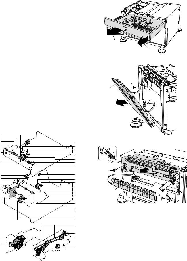
(2) MAINTENANCE AND PARTS REPLACEMENT
(List of Replacement Parts)
No. |
Unit |
|
Parts |
|
|
|
|
|
|
a |
Paper feed unit |
1 |
Pick up roller |
b |
|
|
|
|
|
|
|
2 |
Paper feed roller |
b |
|
|
|
|
|
|
|
3 |
Separate roller |
b |
|
|
|
|
|
|
|
4 |
Torque limiter |
u |
|
|
|
|
|
|
|
5 |
Belts |
u |
|
|
6 |
Upper limit sensor |
u |
|
|
|
|
|
|
|
7 |
Paper empty sensor |
u |
|
|
|
|
|
|
|
8 |
Paper transport sensor |
u |
|
|
9 |
Side door open/close sensor |
u |
|
|
|
|
|
|
|
10 |
Transfer rollers |
u |
|
|
|
|
|
b |
Tand em tray |
1 |
Pick up roller |
b |
|
paper feed unit |
|
|
|
|
2 |
Paper feed roller |
b |
|
|
|
|||
|
|
|
|
|
|
|
3 |
Separate roller |
b |
|
|
|
|
|
|
|
4 |
Torque limiter |
u |
|
|
5 |
Belts |
u |
|
|
|
|
|
c |
Transfer unit |
1 |
Transfer roller |
u |
|
|
|
|
|
d |
Multi-purpose |
1 |
Gears |
u , |
|
drive unit |
|
|
|
|
|
|
|
|
e |
Tandem drive |
1 |
Gears |
u , |
|
unit |
|
|
|
|
2 |
Belts |
u |
|
|
|
|||
|
|
|
|
|
f |
Other |
1 |
Rear edge size PWB |
|
|
|
|
|
|
|
|
2 |
Remaining paper quantity sensor |
u |
|
|
|
|
|
|
|
3 |
Control PWB |
|
|
|
|
|
|
|
|
4 |
Sensor PWB |
|
|
|
|
|
|
|
|
5 |
Paper transfer sensor |
u |
|
|
|
|
|
|
|
6 |
Tandem tray open/close sensor |
u |
|
|
|
|
|
a. Paper feed unit
1)Pull out the multi-purpose tray.
First, pull out the right side of the tray, and then pull out the left side.
2)
1)
2) Remove the left door.
1)
2)
1)
a-5 |
|
|
|
a |
|
3) Remove the multi-purpose paper feed unit. |
|
f-2 |
f-1 |
|
|
a-10 |
|
|
|
a-6 |
8) |
|
|
a-5 |
|
||
a-7 |
7) |
|
|
a-9 |
|
|
|
a-4 |
a-1 |
|
|
a-2 |
|
|
|
a-3 |
|
|
|
a-8 |
|
|
|
|
a-10 |
6) |
|
|
|
|
|
f-4 |
b-6 |
|
|
f-2 |
b-5 |
|
|
f-5 |
|
|
|
b-1 |
|
|
|
f-2 |
|
|
|
b-2 |
|
|
|
f-5 |
6) |
|
|
f-4 |
b-3 |
3) |
|
f-3 |
b-4 |
|
|
b-5 |
b |
|
|
|
c-1 |
4) |
|
|
c |
5) |
|
|
c-1 |
|
|
|
b-1 |
|
|
|
b-2 |
|
|
|
b-3 |
|
|
|
b-4 |
|
|
|
e-2 |
|
|
|
e-1 |
|
|
b |
e |
|
|
b-1 |
e-1 |
|
|
|
|
|
AR-D28/D27/MU2 DISASSEMBLY AND ASSEMBLY, MAINTENANCE
7 – 4

a-1. |
Pick up roller |
a-5. Belts |
a-2. |
Paper feed roller |
1) Remove the paper feed unit. |
a-3. |
Separate roller |
|
a-4. |
Torque limiter |
|
1) Pull out the multi-purpose tray.
2) Remove the paper guide.
2)
2) Remove the pickup roller and paper feed roller.
3) Disengage the roller hook, and remove the roller.
a
3)
*When installing the roller, check to ensure that the hook is securely engaged in the groove.
4) After removing the roller, remove the torque limiter.
b
*When installing the torque limiter, check to ensure that the pin is fully inserted into the torque limiter groove.
a-6. Upper limit sensor a-7. Paper empty sensor
a-8. Paper transport sensor
a-9. Side door open/close sensor
1) Remove the paper feed unit.
1)
1)
1) 
2)
1)
3) 
a 4)
3) 
4)
a
4) |
3) |
a
a
AR-D28/D27/MU2 DISASSEMBLY AND ASSEMBLY, MAINTENANCE
7 – 5
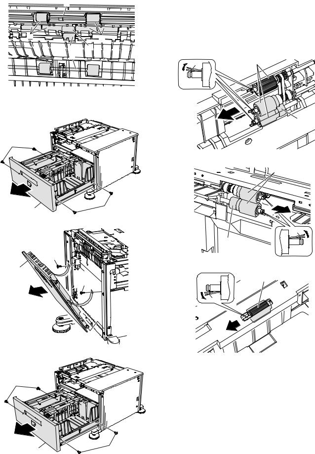
a-10. Transfer rollers
1) Remove the paper feed unit.
a
b
b
b a
a
b. Tandem tray paper feed unit
1) Remove the stopper screw, and pull out the large capacity tray.
2)
1) |
2) |
2) Remove the left door.
1)
2)
1)
3) Remove the tandem paper feed unit.
2)
b-1. Pick up roller
b-2. Paper feed roller
b-3. Separate roller
b-4. Torque limiter
1)Remove the stopper, and pull out the large capacity tray.
2)Disengage the roller hook, and remove the roller and the torque limiter.
• Tandem tray 1
2) |
a |
|
b
• Tandem tray 2
a
2)
b
a
2)
*When installing the roller, check to ensure that the hook is securely engaged in the groove.
*When installing the torque limiter, check to ensure that the pin is fully inserted into the torque limiter groove.
1) |
2) |
AR-D28/D27/MU2 DISASSEMBLY AND ASSEMBLY, MAINTENANCE
7 – 6

b-5. Belts |
2) Remove the transfer unit. |
1) Remove the stopper, and pull out the large capacity tray.
4)
3) 

5)
3)

• Tandem tray 1
c-1. Transfer roller
1) Pull out the multi-purpose tray.
a
• Tandem tray 2
b
d. Multi-purpose drive unit
c. Transfer unit
1) Remove the left door.
1)
2)
1) Remove the rear cabinet.
1)
1)
2)
1)
AR-D28/D27/MU2 DISASSEMBLY AND ASSEMBLY, MAINTENANCE
7 – 7

2) Remove the multi-purpose tray drive section.
 5)
5)
4)
4)
3)
f-1. Rear edge size PWB
f-2. Remaining paper quantity sensor f-3. Control PWB
f-4. Sensor PWB
f-5. Paper transfer sensor
f-6. Tandem tray open/close sensor
1) Remove the rear cabinet.
d-1. Gears
1) Remove the multi-purpose tray drive section.
1)
2)
1)
2) Remove the control PWB and the sensors.
a
e. Tandem drive unit |
a |
1) Remove the tandem tray drive section.
|
10) |
|
|
6) |
7) |
|
|
|
a |
|
|
|
11) |
|
a |
6) |
a |
|
|
|
|
||
6) |
|
|
|
8) |
|
10) |
10) |
|
|
7)
 7)
7)
6)
e-1. Gears
e-2. Belts
2) Remove the tandem tray drive section.
AR-D28/D27/MU2 DISASSEMBLY AND ASSEMBLY, MAINTENANCE
7 – 8
Loading...