


AR-SP3
AR-FX3
AR-DE9
AR-SP3
CODE: 00ZAR15OPTA1E
DIGITAL COPIER OPTIONS
AR-SP3 (SPF)
AR-FX3 (FAX)
AR-DE9 (1 TRAY UNIT) MODEL AR-PG1 (GDI + USB Kit)
For the specifications, operational descriptions, circuit diagrams, and Parts Guide of the AR-FX3, refer to the AR-F151
Service Manual and Parts Guide.
AR-PG1
|
|
CONTENTS |
|
|
|
[ 1 ] GENERAL . . . . . . . . . . . . . . . . . . . . . . . . . . . |
1 |
- 1 |
|||
[ 2 |
] UNPACKING AND INSTALLATION . . . . . . . . . . . . . |
2 |
- 1 |
||
[ 3 |
] AR-SP3 . . . . . . . . . . . . . . . . . . . . . . . . . . . . |
3 |
- 1 |
||
[ 4 |
] AR-DE9 . . . . . . . . . . . . . . . . . . . . . . . . . . . . |
4 |
- 1 |
||
[ 5 |
] AR-PG1 . . . . . . . . . . . . . . . . . . . . . . . . . . . . |
5 |
- 1 |
||
● PARTS GUIDE
Parts marked with “  ” are important for maintaining the safety of the set. Be sure to replace these parts with specified ones for maintaining the safety and performance of the set.
This document has been published to be used
SHARP CORPORATION for after sales service only.
The contents are subject to change without notice.
AR-SP3
[1] GENERAL
1. List of available options
Model |
AR-150 |
AR-155 |
AR-F151 |
|
Option |
||||
|
|
|
||
AR-SP3 |
1 |
|
|
|
(SPF) |
|
|
||
|
|
|
||
AR-FX3 |
1 |
|
|
|
(FAX) |
|
|
||
|
|
|
||
AR-DE9 |
|
|
1 |
|
(1 TRAY UNIT) |
|
|
||
|
|
|
||
AR-PG1 |
|
|
|
|
(GDI + USB Kit) |
|
|
|
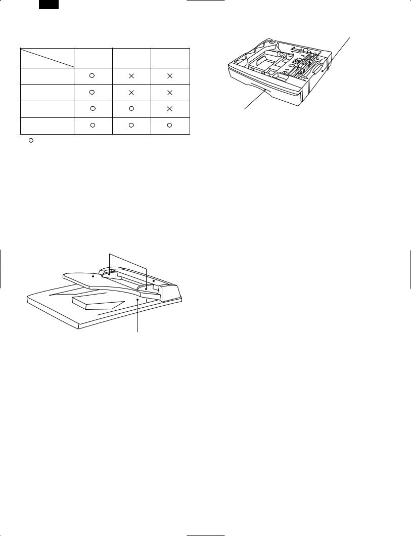
: Option available
 : Option not available
1: The option setup is provided in the models for Europe. FAX and SPF are incompatible.
2.Outline and specifications of each option
A. AR-SP3 (Single Pass Feeder)
The single pass feeder (SPF) holds up to 30 originals for automatic feeding.
Part names
Original guides
Document feeder tray |
Feeding roller cover |
||
|
|
|
|
|
|
|
|
|
|
|
|
|
|
SPF exit area |
|
Specifications |
|
|
|
|
|
||
Acceptable |
Weight: 14 to 23 lbs. |
||
|
|
||
Size: |
5-1/2″ × 8-1/2″ to 8-1/2″ × 14″ |
||
originals |
|||
|
Capacity: Up to 30 sheets |
||
|
|
||
Power supply |
Drawn from the copier |
||
|
|
||
Weight |
Approx.6.6 lbs.(3kg) |
||
|
|
||
Dimensions |
19.6″ (W) × 15″ (D) × 4.3″ (H) |
||
(498 mm (W) × 380 mm (D) × 110 mm (H)) |
|||
|
|||
|
|
|
|
B AR-DE9 (250 - Sheet Paper Feed Unit)
The paper feed unit provides the convenience of increased paper capacity for the copier and a greater choice of paper sizes readily available for copying.
Part names
Side cover
Tray
Specifications
Copy paper size |
5-1/2″ × 8-1/2″ to 8-1/2″ × 14″ |
|
|
|
|
Paper weight |
15 lbs. to 21 lbs. |
|
|
|
|
Paper capacity |
One paper tray with capacity for 250 sheets |
|
of 21 lb. bond paper |
||
|
||
|
|
|
Weight |
Approx. 6.6 lbs. (3 kg) |
|
|
|
|
Dimensions |
19.6″ (W) × 15.6″ (D) × 3.5″ (H) |
|
(498 mm (W) × 395 mm (D) × 88 mm (H)) |
||
|
||
|
|
|
Power supply |
Drawn from the copier |
|
|
|
C. AR-PG1 (GDI + USB Expansion Kit)
(1) MAIN FEATURES
a.Printing from Windows 3.1x, Windows 95, Windows 98*, and Windows NT 4.0 applications
USB is supported on Windows 98 pre-installed only.
●High-speed and high-quality printing can be performed from Windows 3.1x, Windows 95, Windows 98, and Windows NT 4.0 applications through the SHARP GDI (Graphics Device Interface) system.
●Since print data is processed in the computer, waiting time during printing is short.
b. High-speed printing at 8 pages/min.
●First print time is approximately 9.6 seconds.
(Excluding the communication time with PC)
●Print speed is 8 pages/min., when printing multiple pages.
(2) SPECIFICATIONS
Resolution |
600 or 300 can be selected. |
|
|
|
|
Page description |
SHARP GDI (Parallel) |
|
language |
SHARP GDI, USB (USB) |
|
|
|
|
Page orientation |
Portrait or landscape |
|
|
|
|
First print time |
Approx. 9.6 seconds* |
|
|
|
|
|
Approx. 8 pages per minute (letter or A4) |
|
Print speed |
(Parallel) |
|
(multiple pages) |
Approx. 6 pages per minute (letter or A4) |
|
|
(USB) |
|
|
|
|
|
Bi-directional parallel interface |
|
Interface port |
(IEEE 1284 compliant) 2 m (6 feet) Max. |
|
USB (B-type) interface (twisted pair cable) |
||
|
||
|
2 m (6 feet) Max. |
|
|
|
First print time may differ depending on operating conditions, such as power-supply voltage and room temperature.
Also the time may differ depending on data quantity to be printed and applications.
D.AR-FX3 (Facsimile Expansion Kit)
Refer to the AR-F151 Service Manual.
1 – 1

[2] UNPACKING AND INSTALLATION
1. AR-SP3 Instalation Manual
Turn the main switch to the “OFF” position and remove the power plug from the outlet.
1)Remove the document cover.
●Remove the document cover from the copier.
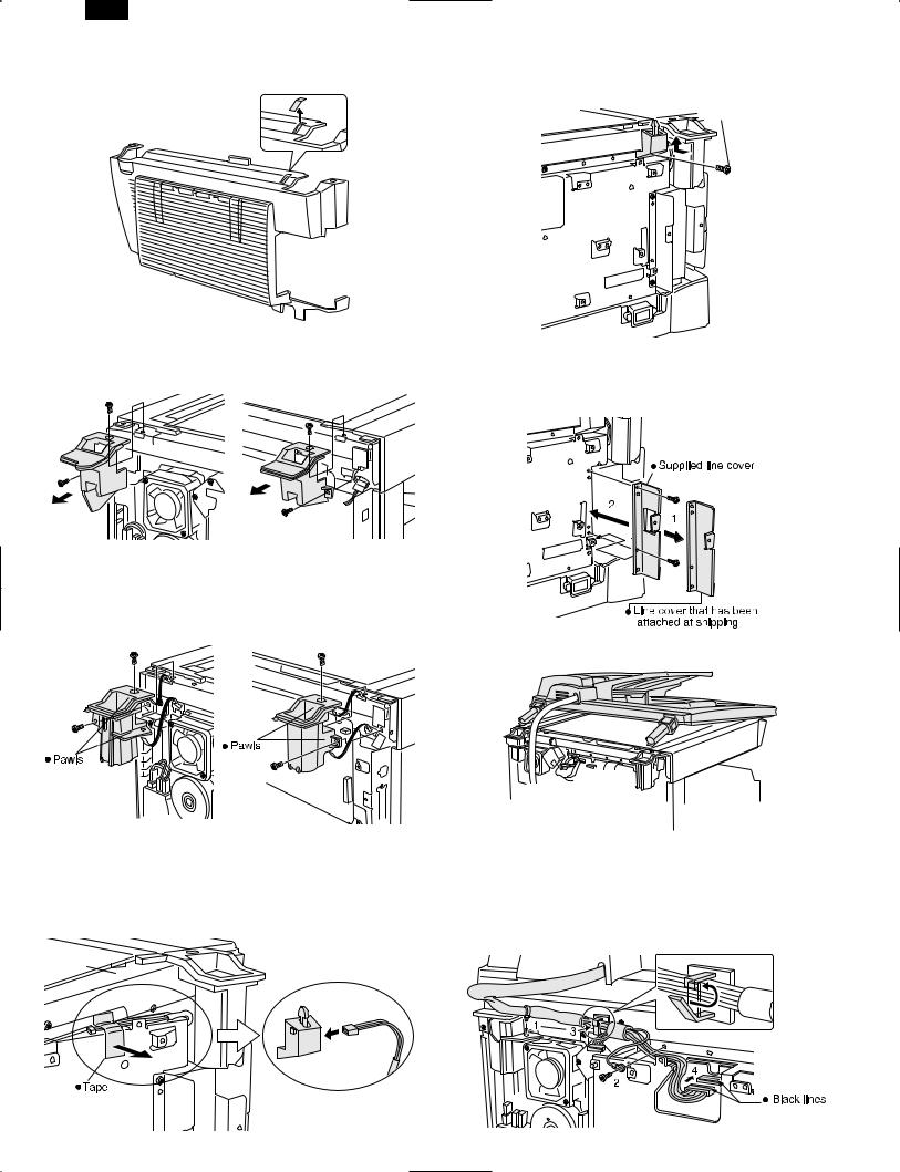
2)Remove the rear cabinet.
●Remove the four screws and then remove the rear cabinet.
AR-SP3
3)Remove the Mylar sheet from the rear cabinet.
●Remove the Mylar sheet that covers the hole for the actuator of sensor unit.
4)Remove the hinge guides L and R.
●Remove the screws (two for each) and then remove the hinge guides L and R.
5)Attach the hinge guides L and R.
●Attach the hinge guides L and R by fitting the pawls (two for
each) into the frame of the copier and secure them with the two screws (M3 × 8) for each that have been removed in step 3.
6) Place the SPF on the copier.
2 – 1

AR-SP3
7) Connect the SPF with the copier using the relay harness.
<1> Fit the snap band to the position shown in the illustration. <2> Attach the core to the relay harness. At this time, take care on
the core position and twist the harness two or three times.
<3> Secure the relay harness with the harness clamp. <4> Connect the connector.
(Connect the connectors by aligning the black lines.)
8) Attach the core to the ground wire and secure it.
<1> Attach the core with two binding bands as shown in the illustration by taking care that the core is in the specified position.
<2> Secure the ground wire to the hinge guides with the binding bands.
<3> Secure the ground terminal to the frame of the copier with a screw (M3 × 10) and handle the wiring so that the core is under the hinge guides.
9)Remove the securing tape of the relay harness and connect the harness to the sensor unit.
●Remove the tape that secures the harness.
Then connect the connector of the relay harness to the supplied sensorunit.
10)Attach the sensor unit.
●While pushing up the sensor unit fully, secure it to the PWB holder with a screw (M3 × 8).
M3X8
11)Attach the rear cabinet.
●Remove the rib from the rear cabinet.
<1> Hang the four pawls shown in the illustration below on the plate.
<2> Push down the actuator of the sensor unit.
<3> Position the cabinet to the upper screw positions.
<4> Ensure that the actuator is inserted into the square hole of the cabinet.
Note: While pushing down the actuator of the sensor unit, attach the rear cabinet so that the actuator is inserted into the hole of the rear cabinet.
12) Attach the cover to the rear cabinet.
<1> Align the arrow marks as shown in the illustration.
<2> Then slide the cover to the left. <3> Secure the cover with a screw.
2 – 2

AR-SP3
2. AR-FX3 Installation Manual
13) Attach the SPF to the copier.
● Attach the SPF by inserting the hinge guide sections of the SP3 into the hinge guides L and R.
1
2 |
2 |
|
14)Insert the power plug into the outlet and turn the main switch of the copier to the “ON” position.
15)Perform SIM setting.
●Execute simulation [2] of [26] and enter [1].
16)Check the ON/OFF operation of the open detection sensor and book detection sensor.
●Execute simulation [2] of [2] and check that the indicator on the operation panel lights up and goes out by opening and closing the SPF. When the book detection sensor is turned ON/OFF, the drum replacement lamp is turned ON/OFF accordingly.
17)Check the copy ratio, and then check the center displacement and leading edge image void.
●Place an original on the document glass and make a copy.
Then, place an original in the document feeder tray and make a copy.
If the center of the copy from the document glass is displaced from the copyfrom the document feeder, adjust the center referring to the service manual.
 Circuit standard label, 1 sheet
Turn the main switch to the “OFF” position and remove the power plug from the outlet.
1)Remove the document cover and the rear cabinet.
●After removing the document cover, remove the four screws and then remove the rear cabinet.
2 – 3
AR-SP3
2)Remove the Mylar sheet from the rear cabinet.
●Remove the Mylar sheet that covers the hole for the actuator of sensor unit.
3)Remove the hinge guides L and R.
●Remove the screws (two for each) and then remove the hinge guides L and R.
4)Attach the hinge guides L and R.
●Attach the hinge guides L and R by fitting the pawls (two for
each) into the frame of the copier and secure them with the two screws (M3 × 8) for each that have been removed in step 2.
5)Remove the securing tape of the relay harness and connect the harness to the sensor unit.
●Remove the tape that secures the harness.
Then connect the connector of the relay harness to the supplied sensor unit.
6)Attach the sensor unit.
●While pushing up the sensor unit fully, secure it to the PWB holder with a screw (M3 × 8).
 M3X8
M3X8
7)Replace the line cover.
●Remove the two screws, replace the line cover that has been attached at shipping with the supplied line cover, and secure it with the two screws.
8) Place the SPF on the copier.
9) Connect the SPF to the copier with the SPF relay harness. <1> Fit the snap band to the position shown in the illustration.
<2> Remove the screw that secures the PWB holder and tighten the ground wire together with the PWB holder.
<3> Secure the relay harness with the harness clamp.
<4> Connect the connector.(Connect the connectors by aligning the black lines.)
2 – 4

10)Attach the fax PWB.
●While ensuring that the connector of the fax PWB is securely
connected to that of the copier, attach the fax PWB to the PWB cover with seven screws (M3 × 6) and connect the relay harness
connector.
Connect the relay harness to the connector of the fax PWB.
(Connect the connectors by aligning the black lines.)
AR-SP3
13) Attach the cover to the rear cabinet.
<1> Align the arrow marks as shown in the illustration. <2> Then slide the cover to the left.
<3> Secure the cover with a screw.
11)Attach the PWB cover.
●Attach the supplied PWB cover with five screws (M3 × 6).
M3X6
M3X6
M3X6
M3X6
12) Attach the rear cabinet.
<1> Hang the four pawls shown in the illustration below on the plate.
<2> Push down the actuator of the sensor unit.
<3> Position the cabinet to the upper screw positions.
<4> Ensure that the actuator is inserted into the square hole of the cabinet.
Note: While pushing down the actuator of the sensor unit, attach the rear cabinet so that the actuator is inserted into the hole of the rear cabinet.
14)Attach the SPF to the copier.
●Attach the SPF by inserting the hinge guide sections of the FX3 into the hinge guides L and R.
1
2 |
2 |
|
15)Stick the label to the rear cabinet.
●After installing the FAX expansion kit in the machine, please put the registration label, packed with the kit, on the prescribed location.
For the details,refer to the AR-FX3 Installation Manual.
2 – 5

AR-SP3
16)Insert the power plug into the outlet and turn the main switch of the copier to the “ON” position.
17)Perform SIM setting.
Execute simulation [2] of [26] and enter [1].
18)Check the ON/OFF operation of the open detection sensor and book detection sensor.
●Execute simulation [2] of [2] and check that the indicator on the operation panel lights up and goes out by opening and closing the FAX-SPF. When the book detection sensor is turned ON/OFF, the drum replacement lamp is turned ON/OFF accordingly.
19)Check the copy ratio, and then check the center displacement and leading edge image void.
●Place an original on the document glass and make a copy. Then, place an original in the document feeder tray and make a copy. If the center of the copy from the document glass is displaced from the copy from the document feeder, adjust the center referring to the service manual.
3. AR-DE9 Installation Manual
Turn the main switch to the “OFF” position and remove the power plug from the outlet.
1)Remove the DV cartridge from the copier.
●Open the bypass tray, side cover, and front cover, and then remove the DV cartridge.
1
3
2
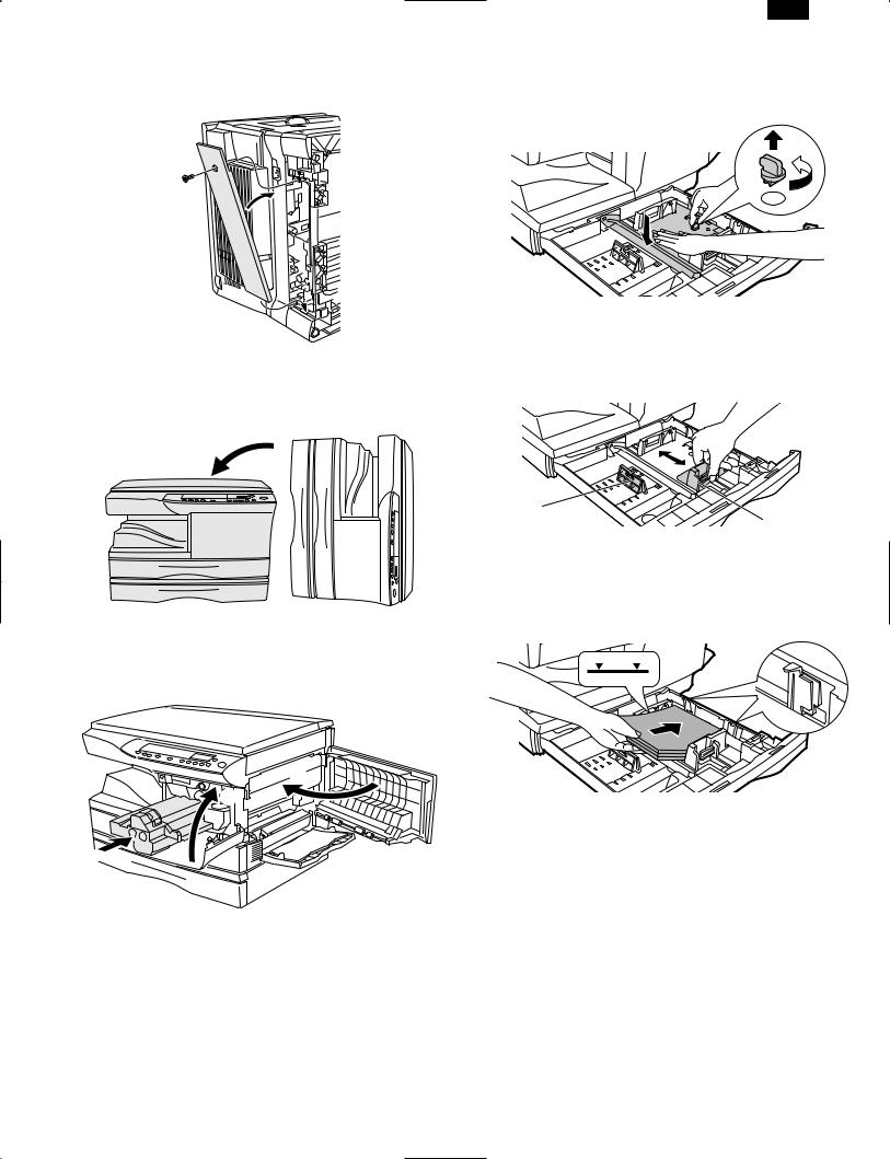
2)Make the copier upright.
●Close the front cover, side cover, and bypass tray, and then make the copier upright in the orientation shown in the illustration.
3)Remove the OP gear cover and rubber feet from the bottom of the copier.
●Remove the screw and remove the OP gear cover.
Then, take off and remove the rubber feet.
4)Install the second cassette unit to the copier.
●If the second cassette unit is aligned to the copier, it can be positioned automatically.
Hold the copier lightly to prevent it from toppling down and secure the second cassette unit with four screws (M4 × 16).
5)Remove the rear cover and connect the connector.
●Remove the screw and remove the rear cover.
Then, connect the connector of the second cassette unit to that of the copier.
2 – 6
6)Attach the rear cover.
●Attach the rear cover to its original position and secure it with the screw (M4 × 12).
7)Return the copier to the normal orientation.
●When returning the copier to the normal orientation, gently return it without giving a shock.
AR-SP3
9)Remove the paper tray lock for packing.
●Remove the paper tray lock for packing that secures the turning plate in the paper tray by rotating it in the direction of the arrow and store it in the specified position.
10)Set the paper tray side guide.
●Squeeze the lever of the paper tray side guide to slide the guide to the position for the paper size to be used.
8)Insert the DV cartridge into the copier.
●Open the bypass tray, side cover, and front cover, and insert the
DV cartridge. Then, close the front cover, side cover, and bypass tray.
3
2 |
1
Paper guide (B) |
Paper guide (A) |
11)Load paper into the paper tray.
●When loading paper, do not exceed the maximum height line.
12)Remove the optical locking screw and fusing unit packing lever so that the copier is ready.
13)Insert the power plug into the outlet and turn the main switch to the “ON” position. Then, perform the following procedure.
14)Perform SIM setting.
●Execute simulation [3] of [26] and enter [1].
15)Check the center displacement.
●Place an original on the document glass and make a copy using the tray in the copier.
Then, make a copy using the tray in the installed optional paper feed unit.
If the center of the copy from the optional paper feed unit is displaced from the copy from the tray in the copier, adjust the center referring to the service manual.
2 – 7

AR-SP3
4. AR-PG1
A. Installation Manual
3)Attach the GDI interface PWB.
●Fit the connector of the GDI PWB into the mounting position of the copier, secure the side A with three screws, and then secure the front B with two screws.
A
B
M3X8
M3X8
Turn the main switch to the “OFF” position and remove the power plug from the outlet.
1)Remove the cover of the rear cabinet.
●Remove the screw, slide the cover in the direction indicated by the arrow, and remove the cover of the rear cabinet.
2) Remove the PWB cover.
<1> Loosen the screws that secure the PWB cover. <2> Push up the PWB cover and
<3> Rotate it counterclockwise to remove it.
2
1
3
1
4)Attach the GDI harness.
●Attach the GDI harness so that the blue lines face forward and also face toward the GDI interface side.
Note: Be careful about the direction of the blue lines.
5) Attach the PWB cover.
<1> Before attaching the PWB cover, hold down the GDI harness in the direction A in the illustration below.
<2> Fit the upper part of the PWB cover to the upper screw that has been loosened in step 2 above.
<3> While rotating the lower part of the PWB cover clockwise, fit it to the lower screw.
<4> Tighten the upper and lower screws to secure the cover.
2 – 8
6)Attach the rear cover.
●Align the arrow marks as shown in the illustration and then slide the cover to the left. Then, secure the cover with a screw.
Arrow marks |
After sliding |
AR-SP3
(3) Installing the printer driver
The software for your printer is provided on CD-ROM.
Before installing the printer driver, be sure to check the following items.
●Is the printer connected properly to the computer?
●Does the printer have paper?
●Is there another GDI printer driver or Windows Printing System printer driver already installed? If installed, change the printer
port setting. To change the printer port settings.
In this description, the following drive configuration is presumed.
Specify proper drives depending on the configuration of your computer. Drive R: CD-ROM drive (installation source). If necessary,
replace R with the letter of your CD-ROM drive.
Drive C: Hard disk drive (installation destination). If necessary, replace C with the letter of your hard disk drive.
a. Windows 95/Windows NT 4.0 Installation Instructions:
With both the computer and the printer turned off, connect the printer to the computer with a parallel interface cable.
1)Load paper into the paper tray of the printer. For instructions on loading paper, see the section LOADING COPY PAPER in the copier operation manual.
2)Turn on the printer.
3)Turn on your computer and start Windows.
4)When using Windows 95 on a personal computer with plug & play*, the “Update Device Driver Wizard” window will appear. Insert the installation CD-ROM into the CD-ROM drive. Click the Next button and follow the on-screen instructions. Proceed to step 7. If the
“Copying Files” window appears during this operation, enter R:\ (if the CD-ROM is designated as drive R) and click the OK button.
B. Installing the printer driver software
(1) Description of the printer driver
The printer driver is the software program which runs the printer. It converts the data in your file into information that the printer can understand. It also controls communication between the printer and computer as the data is printed.
(2) Checking the hardware and software requirements
You will need the following hardware and software in order to install the printer driver.
Computer type |
IBM PC/AT or compatible computer |
|
equipped with a bi-directional parallel or |
|
USB interface, and CD-ROM drive |
Windows type |
Windows 3.1x, Windows 95, Windows 98*, |
|
Windows NT 4.0 |
|
USB is supported on Windows 98 |
|
preinstalled only. |
CPU |
486DX 66 MHz or better |
Physical RAM |
Windows 95, Windows 3.1x: 8MB (16MB or |
|
more is recommended.) |
|
Windows NT4.0: 12MB (16MB or more is |
|
recommended.) |
|
Windows 98: 16MB (32MB or more is |
|
recommended.) |
Display |
640 480 dots (VGA) or better |
Hard disk free space |
10 MB or more |
Caution: The printer driver included in this product cannot be used under Windows NT3.5x, OS/2, pure MS-DOS and other operating systems which are not described above.
●If you use Windows 95 and the “New Hardware Found” window will appear, click the Driver from Disk Provided by Hardware Manufacturer button and then click OK. Proceed to step 6.
●If you use Windows 95 and the screen shown above or the “New Hardware Found” window does not appear, proceed to step 5.
●If you use Windows NT 4.0, proceed to step 5.
Plug & play
This feature is effective if both the computer and peripheral equipment are equipped with IEEE 1284 compliant parallel interface.
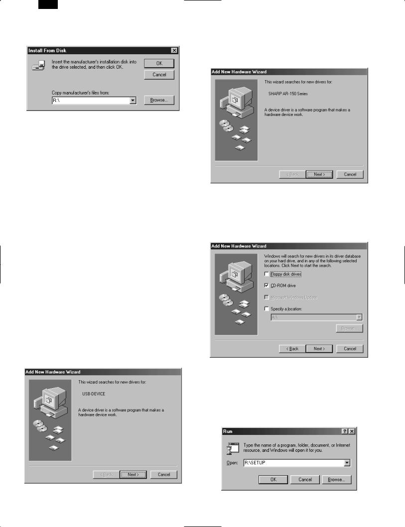
5) Insert the installation CD-ROM into the CD-ROM drive.
Click the Start button and select Run. When the screen shown below appears, type R:\SETUP (if the CD-ROM is designated as drive R) and click the OK button. Proceed to step 7.
2 – 9
AR-SP3
6)“Install from Disk” window will appear. Insert the installation CD-
ROM into the CD-ROM drive. Type R:\ (if the CD-ROM is designated as drive R) and click the OK button. Proceed to step 7.
7)The installation program will start. To install the printer driver to the default folder, click the Next button. To select a different folder, select Browse or type in the new path and folder name. Click OK and say YES to create the folder, select the Next button to continue.
8)On the display, you will see “printer port to be used”. Normally, this is LPT1 and it is selected automatically.
Ensure that Yes is checked to use the printer as the default printer.
Finally click the Next button.
9)A “Confirm installation” window will be displayed. To continue installation, click the Yes button.
10)When the installation is complete, you will be asked whether or not to print a test page. If you wish to do so, click the Yes button. At this time, ensure that paper is loaded in the paper tray.
11)If the test print completes successfully, click the Finish button.
“The installation of the SHARP AR-150 Series Software is complete.” window will be displayed. Click the OK button.
b.Windows 98:
With both the computer and the printer turned off, connect the printer to the computer with either a parallel or a USB interface cable.
1)Load paper into the paper tray of the printer. For instructions on loading paper, see the section LOADING COPY PAPER found in the copier operation manual.
2)Turn on the printer.
3)Turn on your computer and start Windows.
When using the USB interface:
●Connect your personal computer and the printer using a USB interface cable if you have not already done so.
●When the “Add New Hardware Wizard” window appears, insert the installation CD-ROM, click the Next button, follow the onscreen instructions, and finally click the Finish button.
4)When using Windows 98 on a personal computer with plug & play*, the “Add New Hardware Wizard” window will appear. Click the Next
button and follow the on-screen instructions.
●If the “Add New Hardware Wizard” window does not appear, proceed to step 8.
Plug &play: For plug & play information
5)Select Search for the best driver for your device and click the Next button.
6)Insert the installation CD-ROM into the CD-ROM drive. (If you are using the USB interface, confirm that the installation CD-ROM is in the CD-ROM drive.) Select the CD-ROM drive and click the Next button.
7)Windows driver file search will find the device “SHARP AR-150 Series”. Click the Next button. Proceed to step 9.
8)Insert the installation CD-ROM into the CD-ROM drive. (If you are using the USB interface, confirm that the installation CD-ROM is in the CD-ROM drive.) Click the Start button and select Run. When the window shown below appears, type R:\SETUP (if the CD-ROM is designated as drive R) and click the OK button. Proceed to step 9.
2 – 10

9)The installation program will start. To select a different folder, select
Browse and type in the path and folder name where the printer driver will be installed. Click OK and say YES to create the folder, select the Next button to continue. To install the printer driver to the default folder, click the Next button.
10)On the display you will see “printer port to be used”. The printer port is selected automatically. If you are using the parallel interface, this is LPT1. If you are using the USB interface, this is
LPT/USB1. Ensure that Yes is checked to use the printer as the default printer. Finally click the Next button.
11)A “Confirm installation” window will be displayed. To continue installation, click the Yes button.
12)When the installation is complete, you will be asked whether or not to print a test page. If you wish to do so, click the Yes button. At this time, ensure that paper is loaded in the paper tray.
13)If the test print completes successfully, click the Finish button. “The installation of the SHARP AR-150 Series Software is complete.” window will be displayed. Click the OK button.
c. Windows 3.1x:
With both the computer and the printer turned off, connect the printer to the computer with a parallel interface cable.
1)Load paper into the paper tray of the printer. For instructions on loading paper, see the section LOADING COPY PAPER in the copier operation manual.
2)Turn on the printer and then start Windows on your computer.
3)Insert the installation CD-ROM into a CD-ROM drive.
4)Choose File from the Menu bar in Program Manager, and then choose the Run... command.
5)Type R:\SETUP (if the CD-ROM is designated as drive R) in the command line box and then click the OK button.
6)Select a directory to which the printer driver will be installed and click the Next button. To install it to the default directory, click the
Next button.
7)A “printer port to be used” window will be displayed. Normally, LPT1 is automatically set.
Then ensure that Yes is checked to use this printer as the default printer.
8)A “Confirm installation” window will be displayed. To continue installation, click Yes.
9)When the installation is complete, restart Windows.
(4) AR-150 Series printer driver group
When the printer driver is installed, the SHARP AR-150 Series printer driver group will be created. This group of software programs provides the following functions:
AR-SP3
a. Uninstall AR-150 Series
The printer driver can be uninstalled. If the driver is uninstalled, printing can no longer be performed on the printer.
For proper uninstallation, be sure to use the SHARP uninstall program of the printer driver group.
Readme
The latest information on the printer driver is included in this document. Read the Readme first.
Advanced Settings
See help for Advanced Settings.
Status Monitor
The Status Monitor window provides visual information about the printer state and current job.
DOS Emulation Setup
Status Monitor HELP
Assistance and information for Status Monitor.
DOS Emulation HELP
Assistance and information for DOS Emulation support.
Advanced Settings HELP
Assistance and information for Advanced Settings.
2 – 11

AR-SP3
[3] AR-SP3
1. Operational descriptions
A. Outline
The SPF (Single Path Feeder) is installed to the AL-1000/1200 as a standard provision, and it automatically copies up to 30 sheets of documents of a same size. (Only one set of copies)
B. Document transport path and basic composition
(1) |
Pickup roller |
(2) |
Sheet of document for paper feed |
(3) |
Set detection ACT |
|
|
|
|
|
|
(4) |
Paper stopper |
(5) |
Document feed roller |
(6) |
Separation sheet |
|
|
|
|
|
|
(7) |
Paper entry sensor |
(8) |
PS roller D |
(9) |
Transport follower roller |
|
|
|
|
|
|
(10) |
Paper exit roller |
(11) |
Paper exit follower roller |
(12) |
Document tray |
|
|
|
|
|
|
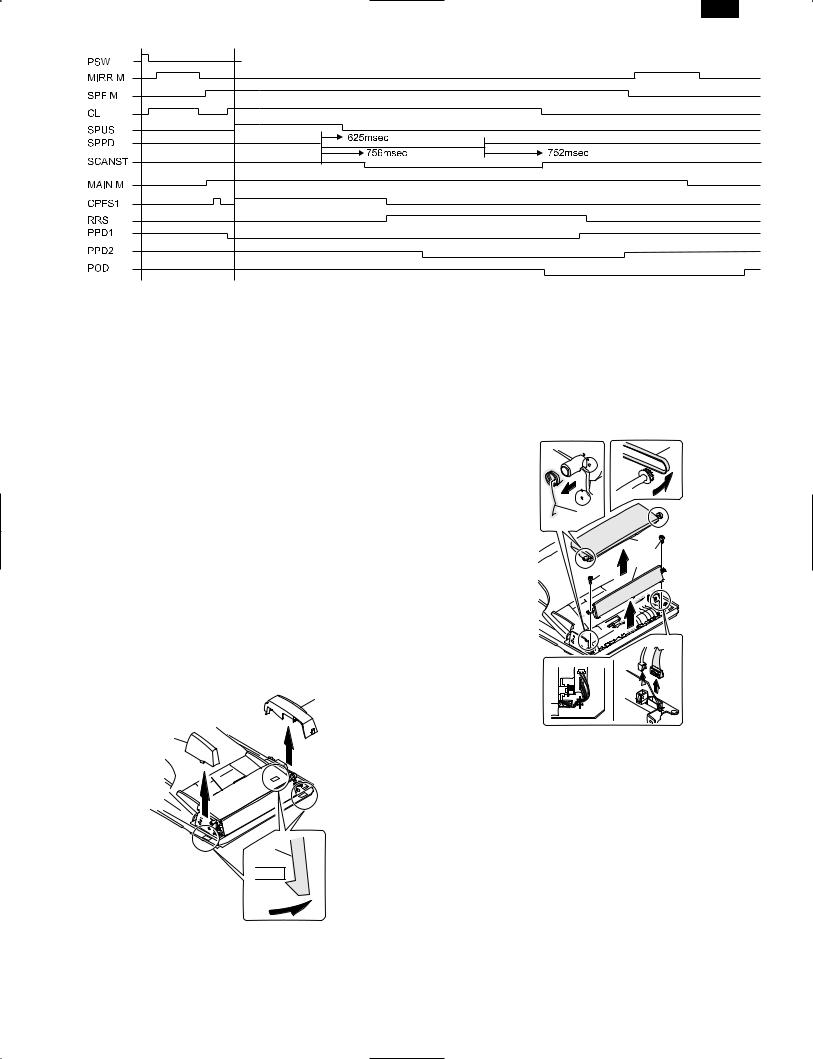
C. Operational descriptions
Time chart (Tray feed)
|
|
|
|
Document set |
|
|
|
|
|
|
|
|
|
|
|
|
|
|
|
|
|
|
|
|
|
|
|
|
|
|
|
|
|
SPID ON |
Document set sensor |
|
|||
|
|
|
|
|
|
|
|
|
|
|
|
|
|
|
|
|
|
||
|
|
Document feed unit lamp ON |
|
|
|
||||
|
|
|
|
|
|
|
|
|
|
|
|
|
|
|
Copy start |
|
|||
|
|
|
|
PSW ON |
|
||||
|
|
|
|
|
The scanner is shifted |
|
|||
|
|
|
|
|
|
||||
|
|
|
|
MIRM rotation |
to the exposure position. |
||||
(Copier side) |
|
|
|
|
(SPF side) |
|
|||
|
|
|
|
|
|||||
|
|
|
|
|
|
SPF motor rotation |
|||
MM rotation |
Main motor rotation |
|
SPFM rotation |
|
|||||
|
Paper feed |
|
|
|
|
|
|||
|
|
|
|
|
|
||||
CPFS ON |
|
|
|
|
|
||||
|
|
|
|
|
|
|
|
|
Document feed |
|
|
|
|
|
|
|
SPUS ON |
|
|
|
|
|
|
|
|
|
|
|
|
PPD ON |
|
|
|
|
|
|
|
|
|
|
|
|
|
|
|
|
|
Document transport sensor |
|
|
|
|
|
|
|
|
|
||
RRC ON |
|
|
Synchronization |
|
|
SPPD ON |
|
||
|
|
|
|
|
|
|
|
|
|
|
|
Paper transport |
|
|
|
|
Document transport |
||
(Transfer) |
|
|
|
|
(Exposure) |
|
|||
(Fusing) |
|
|
|
|
(Document exit) |
|
|||
|
|
|
|
|
|
|
|
|
|
POD ON |
|
|
|
|
|
|
|
|
|
|
|
|
|
|
|
|
|
|
|
(Paper exit)
In the zooming mode, the magnification ratio in the sub scanning direction (paper transport direction) is adjusted by changing the document transport speed.
3 – 1
AR-SP3
D. Cases where a document jam is caused
a.When SPPD is ON (document remaining) when the power is turned on.
b.When SPPD is not turned ON within about 1.5 sec (at 100% copy) after starting the document feed operation.
c.When SPPD is not turned on within about 4.7 sec (at 100% copy) after turning on SPPD.
d.When the SPF document jam release door or the OC cover is opened during document transport (SPF motor rotating).
2. Disassembly and assembly
No. |
Part name Ref. |
|
|
A |
Sensor PWB |
|
|
B |
Pickup solenoid |
|
|
C |
Clutch |
|
|
D |
Manual paper feed roller, pickup roller |
|
|
E |
Belt |
|
|
F |
SPF motor |
|
|
G |
Paper entry sensor |
|
|
H |
PS roller |
|
|
I |
Paper exit roller |
|
|
Pickup unit removal
1)Remove three fixing pawls from the bottom of the machine.
2)Remove the front cover and the rear cover.
2
2
1)Remove the belt, the paper feed frame SP, and two harnesses.
2)Remove the pickup unit.
1
1
2
3
4
3
1 1
1
*When installing the parts, be careful of the hole position of the paper frame SP.
1
3 – 2
 Loading...