


AR-MU1
AR-D13
AR-D14
CODE : 00ZARD13//A1E
LASERPRINTEROPTIONS
PAPERFEEDUNIT
OPTIONALPOWERSUPPLYUNIT
AR-DC1
MODEL
AR-D13 AR-D14 AR-MU1 AR-DC1
CONTENTS
[1] PRODUCT OUTLINE . . . . . . . . . . . . . . . . . . . . . . . . . . . . . . . . 1 - 1 [2] CONFIGURATION . . . . . . . . . . . . . . . . . . . . . . . . . . . . . . . . . . 2 - 1 [3] SPECIFICATIONS . . . . . . . . . . . . . . . . . . . . . . . . . . . . . . . . . . 3 - 1 [4] UNPACKING AND INSTALLATION. . . . . . . . . . . . . . . . . . . . . . 4 - 1 [5] EXTERNAL VIEWS AND INTERNAL STRUCTURES . . . . . . . 5 - 1 [6] ADJUSTMENTS . . . . . . . . . . . . . . . . . . . . . . . . . . . . . . . . . . . . 6 - 1 [7] DISASSEMBLY AND ASSEMBLY, MAINTENANCE. . . . . . . . . 7 - 1 [8] BLOCK DIAGRAM, WIRING DIAGRAM. . . . . . . . . . . . . . . . . . 8 - 1
Parts marked with “ “ are important for maintaining the safety of the set.
Be sure to replace these parts with specified ones for maintaining the safety and performance of the set.
This document has been published to be used for SHARP CORPORATION after sales service only.
The contents are subject to change without notice.

[1] PRODUCT OUTLINE
This unit is installed to one of the following machines to serve as a Paper feed module.
When installing the unit to one of the following machines, one of the multi-purpose tray (AR-MU1), the large capacity paper feed desk (AR-D13), and the 3-stage paper feed desk (AR-D14) must be installed in advance. For the AR-D13 and the AR-D14, the option power unit (AR-DC1) must be installed together.
Applicable models |
AR-P350 / P450, AR-M350 / M450 |
[2] CONFIGURATION
1.For the AR-D13 and the AR-D14, the option power unit (AR-DC1) must be installed together.
2.When the AR-MU1 and the mail bin stacker (AR-MS1) or the finisher (AR-FN6) are installed, the optional power unit (AR-DC1) must be installed together.
3.The AR-MU1 cannot be installed together with the saddle finisher (AR-FN)/Scanner unit (AR-EF1/EF2).
Exit tray |
|
B/W scanner module/DSPF(AR-EF1) |
||
(AR-TE3 or AR-DU4 Standard) |
||||
|
|
|||
|
Duplex |
|
|
|
|
module/bypass tray |
Upper exit tray |
||
|
|
|
||
|
|
|
extension |
|
|
|
|
(AR-TE4) |
|
|
|
Duplex module |
|
|
|
|
(AR-DU3) |
|
|
|
|
|
Finisher |
|
|
|
|
(AR-FN6) |
|
Saddle stitch |
|
finisher |
|
(AR-FN7) |
Mail-bin stacker |
Multi purpose drawer |
|
(AR-MU1) |
(AR-MS1) |
Stand/3 x 500 sheet |
Stand/MPD & 2000 sheet |
paper drawer |
paper drawer |
(AR-D14) |
(AR-D13) |
|
Power supply unit |
|
(AR-DC1) |
Related to paper feed unit |
B/W scanner module/DSPF |
Scanner rack |
Multi purpose drawer |
Stand/3 x 500 sheet paper drawer |
Stand/MPD & 2000 sheet |
Duplex module/bypass tray |
Duplex module |
Saddle stitch finisher |
Finisher |
Mail-bin stacker |
Exit tray |
Upper exit tray extension |
Punch unit |
Multi-function controller board |
Print server card |
PS3 expansion kit |
Network scanner expansion kit |
Facsimile expansion kit |
Fax memory (8 MB) |
Power supply unit |
Hard disk drive |
Multi purpose drawer |
AR-MU1 |
|
|
|
|
|
|
|
|
|
|
|
|
|
|
|
|
|
|
|
|
Stand/3 x 500 sheet paper drawer |
AR-D14 |
|
|
|
|
|
|
|
|
|
|
|
|
|
|
|
|
|
|
|
|
Stand/MPD & 2000 sheet paper drawer |
AR-D13 |
|
|
|
|
|
|
|
|
|
|
|
|
|
|
|
|
|
|
|
|
AR-D13/D14/MU1/DC1 PRODUCT OUTLINE, CONFIGURATION 1-1
[3] SPECIFICATIONS
1. AR-D13
|
|
AR-D13 |
|
|
|
Type |
|
Stand MPD&2000 Sheet Paper Drawer |
|
|
(large capacity tray + multi purpose drawer) |
|
|
|
Transport speed |
To support 35-45 sheet/minute |
|
|
|
|
Transport alignment |
Center alignment |
|
|
|
|
Paper size |
1 Tray |
A3, B4, A4, A4R, B5, B5R, A5R |
|
|
11"x17", 8.5"x14", 8.5"x13", 8.5"x11", |
|
|
8.5"x11"R, 5.5"x8.5"R |
|
|
Executive, Japanese p/c, Monarch(envelope) |
|
|
Com-10(envelope), DL(envelope), |
|
|
C5(envelope), ISO B5(envelope) |
|
|
|
|
2 Tray |
A4, 8.5"x11" |
|
|
|
How to change |
the paper |
Guide adjustment by user / Software setting |
size |
|
by user |
|
|
|
Factory |
1 Tray |
8.5"x11" |
default paper |
|
|
2 Tray |
The size guide plate is packed together. |
|
size setting |
|
|
|
|
|
Media |
1 Tray |
Plain paper:60-128g/m² / 16-34lbs |
available for |
|
Index paper:176g/m² / 47lbs |
paper feeding |
|
Cover paper:200-205g/m² / 54-55lbs |
|
|
|
|
|
Envelope:75-90g/m², 20-24lbs |
|
|
Transparency film |
|
|
* Media heavier than 105g/m² should be |
|
|
A4/8.5x11" or smaller. Media heavier than |
|
|
128g/m² should be fed from shorter edge. |
|
|
* Only single paper feed is enabled for |
|
|
overlay copy or copy on back-side of printed |
|
|
paper. |
|
|
|
|
2 Tray |
Plain 60-105g/m² / 16-28lbs |
|
|
|
Paper |
1 Tray |
Standard:500sheets(80g/m²) |
capacity |
|
Post card:40sheets |
|
|
Envelope:40sheets |
|
|
Transparency film:40sheets |
|
|
|
|
2 Tray |
880+1,320sheets(64g/m²) / |
|
|
800+1,200sheets(80g/m²) |
|
|
|
Paper type |
1 Tray |
Plain, recycled, pre-printed, pre-punched, |
|
|
color, letter head, labels, heavy, |
|
|
transparency, Japanese p/c, envelope |
|
|
(User can set bi-type for each of the above |
|
|
paper type.) |
|
|
|
|
2 Tray |
Plain, recycled, pre-printed, pre-punched, |
|
|
color, letter head |
|
|
(User can set bi-type for each of the above |
|
|
paper type.) |
|
|
|
Sizes to be |
1 Tray |
AutomaticAuto-AB: |
detected |
|
A3, B4, A4, A4R, B5, B5R, 8.5"x13", A5R |
|
|
|
|
|
AutomaticAuto-Inch: |
|
|
11"x17", 8.5"x14", 8.5"x11", 8.5"x11"R, |
|
|
7.25"x10.5"R, 5.5" x 8.5R |
|
|
|
|
|
Manual (input detection): |
|
|
postal card, Monarch(envelope), |
|
|
Com-10(envelope), DL(envelope), |
|
|
C5(envelope), ISO B5(envelope) |
|
|
|
|
|
Ignore detection selectable: |
|
|
|
|
2 Tray |
Size setting by the serviceman |
|
|
|
Paper balance |
1 Tray |
Provided (paper empty and 3 steps) |
detection |
|
|
2 Tray |
Enable (Paper empty and 6 steps |
|
|
|
(3 steps + 3 steps)) |
|
|
|
Paper loading |
system |
To be loaded from the upper side with front |
|
|
loading system |
|
|
|
|
|
AR-D13 |
|
|
|
Tray ascent/ |
Ascent |
Within 12 seconds |
descent time |
|
|
|
At paper empty, required time from tray insert |
|
|
|
to the empty detection |
|
|
|
|
Descent |
Own weight descent |
|
|
|
Dehumidification |
heater |
Not provided |
|
|
|
Power consumption |
32.2W or lower |
|
|
|
|
Power source |
Supplied from main unit |
|
|
|
(DC24V 1.3A / DC5V 0.2A) |
|
|
|
External dimensions |
619x664x404 (mm) |
|
|
|
|
Occupied dimensions |
745x664 (mm) |
|
|
|
|
Weight |
Approx. 34kg |
|
|
|
|
2. AR-D14
|
|
AR-D14 |
|
|
|
Type |
|
Stand /3x500 Sheet Paper Drawer |
|
|
(2 paper trays + 1 multi purpose drawer) |
|
|
|
Transport speed |
To support 35-45 sheet/minute |
|
|
|
|
Transport alignment |
Center alignment |
|
|
|
|
Paper size |
1 Tray |
A3, B4, A4, A4R, B5, B5R, A5R |
|
|
11"x17", 8.5"x14", 8.5"x13", 8.5"x11", |
|
|
8.5"x11"R, 5.5"x8.5"R |
|
|
Executive, Japanese p/c,Monarch(envelope) |
|
|
Com-10(envelope), DL(envelope), |
|
|
C5(envelope), ISO B5(envelope) |
|
|
|
|
2 or 3 |
A3, B4, A4, A4R, B5, B5R |
|
Tray |
11"x17", 8.5"x14", 8.5"x13", 8.5"x11", |
|
|
8.5"x11"R, 7.25"x10.5"R |
|
|
|
How to change |
the paper |
Unit is delivered with paper guide set at max. |
size |
|
position in width. (Both of two cassettes.) |
|
|
|
Factory default paper |
To be set to maximum paper guide width at |
|
size setting |
|
factory default status (for both trays) |
|
|
|
Media |
1 Tray |
Plain paper:60-128g/m² / 16-34lbs |
available for |
|
Index paper:176g/m² / 47lbs |
paper feeding |
|
Cover paper:200-205g/m² / 54-55lbs |
|
|
Envelope:75-90g/m², 20-24lbs |
|
|
Transparency film |
|
|
* Media heavier than 105g/m² should be |
|
|
A4/8.5x11" or smaller. Media heavier than |
|
|
128g/m² should be fed from shorter edge. |
|
|
* Only single paper feed is enabled for |
|
|
overlay copy or copy on back-side of printed |
|
|
paper. |
|
|
|
|
2 or 3 |
Plain 60-105g/m² / 16-28lbs |
|
Tray |
|
|
|
|
Paper |
1 Tray |
Standard:500sheets(80g/m²) |
capacity |
|
Post card:40sheets |
|
|
Envelope:40sheets |
|
|
Transparency film:40sheets |
|
|
|
|
2 or 3 |
Standard |
|
Tray |
paper:500sheets X 2(64g/m²) |
|
|
|
Paper type |
1 Tray |
Plain, recycled, pre-printed, pre-punched, |
|
|
color, letter head, labels, heavy, |
|
|
transparency, Japanese p/c, envelope |
|
|
(User can set bi-type for each of the above |
|
|
paper type.) |
|
|
|
|
2 or 3 |
Plain, recycled, pre-printed, pre-punched, |
|
Tray |
color, letter head |
|
|
(User can set bi-type for each of the above |
|
|
paper type.) |
|
|
|
AR-D13/D14/MU1/DC1 SPECIFICATIONS 3-1
|
|
AR-D14 |
|
|
|
Sizes to be |
1 Tray |
AutomaticAuto-AB: |
detected |
|
A3, B4, A4, A4R, B5, B5R, 8.5"x13", A5R |
|
|
|
|
|
AutomaticAuto-Inch: |
|
|
11"x17", 8.5"x14", 8.5"x11", 8.5"x11"R, |
|
|
7.25"x10.5"R, 5.5" x 8.5R |
|
|
|
|
|
Manual (input detection): |
|
|
postal card, Monarch(envelope), |
|
|
Com-10(envelope), DL(envelope), |
|
|
C5(envelope), ISO B5(envelope) |
|
|
|
|
|
Ignore detection selectable: |
|
|
|
|
2 or 3 |
Automatic detection-AB |
|
Tray |
(200V system):A3, B4, A4, A4R, B5, B5R, |
|
|
8.5"x13" |
|
|
|
|
|
Automatic detection-inch |
|
|
(100V system): 11"x17", 8.5"x14", 8.5"x13", |
|
|
8.5"x11", 8.5"x11"R, 7.25"x10.5"R |
|
|
|
Paper balance |
detection |
Provided (paper empty and 3 steps) |
|
|
|
Paper loading system |
To be loaded from the upper side with front |
|
|
|
loading system |
|
|
|
Tray ascent/ |
Ascent |
Within 7 seconds |
descent time |
|
|
|
At paper empty, required time from tray |
|
|
|
insert to the empty detection |
|
|
|
|
Descent |
Own weight descent |
|
|
|
Dehumidification |
heater |
Included in the service kit. |
|
|
|
Power consumption |
32.2W or lower |
|
|
|
|
Power source |
|
Supplied from main unit |
|
|
(DC24V 1.3A / DC5V 0.2A) |
|
|
|
External dimensions |
619x664x404 (mm) |
|
|
|
|
Occupied dimensions |
745x664 (mm) |
|
|
|
|
Weight |
|
Approx. 32kg |
|
|
|
3. AR-MU1
|
|
AR-MU1 |
|
|
|
Type |
Multi purpose drawer |
|
|
|
|
Transport speed |
To support 35-55 sheets/minute |
|
|
|
|
Transport alignment |
Center alignment |
|
|
|
|
Paper size |
A3, B4, A4, A4R, B5, B5R, A5R |
|
|
|
11"x17", 8.5"x14", 8.5"x13", 8.5"x11", |
|
|
8.5"x11"R, 5.5"x8.5"R |
|
|
Executive, Japanese p/c, Monarch(envelope) |
|
|
Com-10(envelope), DL(envelope), |
|
|
C5(envelope), ISO B5(envelope) |
|
|
|
How to change the paper |
Guide adjustment by user / Software setting |
|
size |
by user |
|
|
|
|
Factory default paper |
To be set to maximum paper guide width at |
|
size setting |
factory default status. |
|
|
|
|
Media available for paper |
Plain paper:60-128g/m² / 16-34lbs |
|
feeding |
Index paper:176g/m² / 47lbs |
|
|
|
Cover paper:200-205g/m² / 54-55lbs |
|
|
Envelope:75-90g/m², 20-24lbs |
|
|
Transparency film |
|
|
|
|
|
* Media heavier than 105g/m² should be |
|
|
A4/8.5x11" or smaller. Media heavier than |
|
|
128g/m² should be fed from shorter edge. |
|
|
* Only single paper feed is enabled for |
|
|
overlay copy or copy on back-side of printed |
|
|
paper. |
|
|
|
Paper capacity |
Standard:500sheets(80g/m²) |
|
|
|
Post card:40sheets |
|
|
Envelope:40sheets |
|
|
Transparency film:40sheets |
|
|
|
Paper type |
Plain, recycled, pre-printed, pre-punched, |
|
|
|
color, letter head, labels, heavy, |
|
|
transparency, Japanese p/c, envelope |
|
|
(User can set bi-type for each of the above |
|
|
paper type.) |
|
|
|
Sizes to be detected |
AutomaticAuto-AB: |
|
|
|
A3, B4, A4, A4R, B5, B5R, 8.5"x13", A5R |
|
|
|
|
|
AutomaticAuto-Inch: |
|
|
11"x17", 8.5"x14", 8.5"x11", 8.5"x11"R, |
|
|
7.25"x10.5"R, 5.5" x 8.5R |
|
|
|
|
|
Manual (input detection): |
|
|
postal card, Monarch(envelope), |
|
|
Com-10(envelope), DL(envelope), |
|
|
C5(envelope), ISO B5(envelope) |
|
|
|
|
|
Ignore detection selectable: |
|
|
|
Paper balance detection |
Provided (paper empty and 3 steps) |
|
|
|
|
Paper loading system |
To be loaded from the upper side with front |
|
|
|
loading system |
|
|
|
Tray ascent/ |
Ascent |
Within 7 seconds |
descent time |
|
|
|
At paper empty, required time from tray insert |
|
|
|
to the empty detection |
|
|
|
|
Descent |
Own weight descent |
|
|
|
Dehumidification |
heater |
Included in the service kit. |
|
|
|
Power consumption |
24.5W or lower |
|
|
|
|
Power source |
Supplied from main unit |
|
|
|
(DC24V 1A / DC5V 0.1A) |
|
|
|
External dimensions |
654x567x144 (mm) |
|
|
|
|
Occupied dimensions |
659x567 (mm) |
|
|
|
|
Weight |
Approx. 11kg |
|
|
|
|
4. AR-DC1
Input |
AC 100-127V / 220-240V (Two kinds) |
Output |
DC 24V , 5V |
AR-D13/D14/MU1/DC1 SPECIFICATIONS 3-2

[4] UNPACKING AND INSTALLATION
1.AR-D13
<Before installation>
•Start installation after checking that the DATA and COMMUNICATION indicators on the operation panel are neither lit nor blinking.
•For installation, a power supply unit (AR-DC1) is needed.
•
<Parts included>
|
Front mounting |
Rear mounting |
Screws (M4x8): |
|
|
plates: 2 pcs. |
plates: 2 pcs. |
4 pcs. |
|
Left adjuster: 1 pc. |
|
|
|
|
Adjuster covers: 4 pcs. |
Left paper guides: 2 pcs. |
Right paper guides: 2 pcs. |
||
1)Turn off the main switch of the main unit of the printer.
Turn the main switch located on the front side of the printer to the "OFF" position.
Then remove the power plug from the outlet.
"OFF"
2) Attach the adjusters and adjust them.
<1>Insert the left adjusters to the stand/paper drawer.
<2>Turn the each adjusters to lower them until they touch the floor. <3>Attach the four adjuster covers.
3
3
3 |
|
|
2 |
|
2 |
2 |
3 |
|
1 |
2 |
|
*Be sure to attach the left adjuster to prevent overturning.
Caution: The lower tray cannot be pulled out unless the adjuster is lowered to the specified position.
3) Put the main unit of the printer on the stand/paper drawer.
<1>Pull out the paper tray of the main unit until it stops and then remove it by lifting both ends of the tray.
<2>Hold the main unit of the printer at the positions shown in the illustration and put the main unit on the stand/paper drawer so that the front side and the left side of the main unit are aligned to those of the stand/paper drawer.
Front side
Rear side
Caution: For installation of the main unit, it must be held by two persons and installed without haste.
4) Connect the main unit to the stand/paper drawer.
<1>Attach the rear mounting plates using a supplied screw for each.
Rear mounting plate
Screw Screw
Rear mounting plate
Rear
mounting plate
Desk frame
Caution: Insert the rear mounting plates under the desk frame. <2>Pull out the upper paper tray of the stand/paper drawer until it stops
and attach the front mounting plates using a supplied screw for each. Then, remove the lock of the paper tray and close the tray.
Front mounting plate
Screw
Front mounting |
Screw |
|
plate |
||
|
AR-D13/D14/MU1/DC1 UNPACKING AND INSTALLATION 4-1
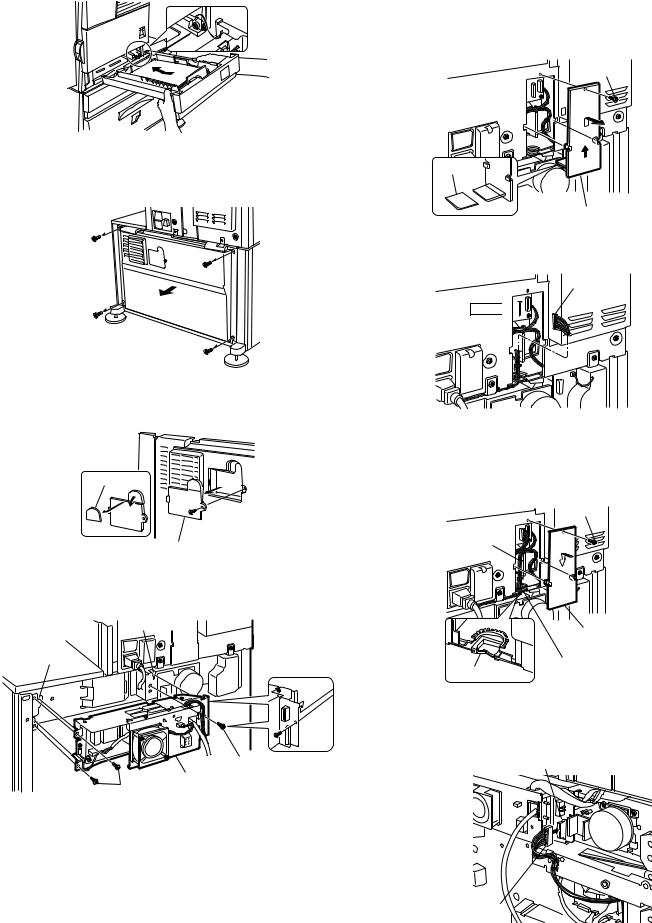
<3>Reattach the paper tray of the main unit.
7)Connect the power supply unit harness to the PCU PWB of the main unit of the printer.
<1>Remove the screw that fixes the harness cover of the main unit of the printer and slide the harness cover up to remove it.
Process the harness cover as shown in the illustration.
Screw
5)Remove the rear cabinet of the stand/paper drawer and remove the AC inlet cover.
<1>Remove the four screws that fix the rear cabinet and then remove the rear cabinet.
Rear cabinet
Cut out.
Harness cover
<2>Connect the optional power supply harness connector to CN11 (red connector) of the PCU PWB of the main unit of the printer.
Connector
CN11 


<2>Remove the screw that fixes the AC inlet cover and then remove the AC inlet cover.
<3>Process the AC inlet cover as shown in the illustration.
Cut out.
AC inlet cover
6)Attach the power supply unit (AR-DC1).
Attach the power supply unit to the hanging portions and secure it using the three supplied screws.
Hanging portion
Hanging portion
|
Screws |
Screws |
Power supply unit |
|
<3>Reattach the harness cover to its original position and fix it with the removed screw.
At this time, ensure that the optional power supply harness are arranged as shown in the illustration.
•Fix the harness securely to the wire saddle.
Screw
Optional power supply harness
Harness cover
Wire saddle
Wire saddle
8)Connect the relay harness of the stand/paper drawer to the power supply unit.
Connect the relay harness of the stand/paper drawer to the connector of the power supply unit.
Connector of the power supply connector
Relay harness of the stand/paper drawer
AR-D13/D14/MU1/DC1 UNPACKING AND INSTALLATION 4-2
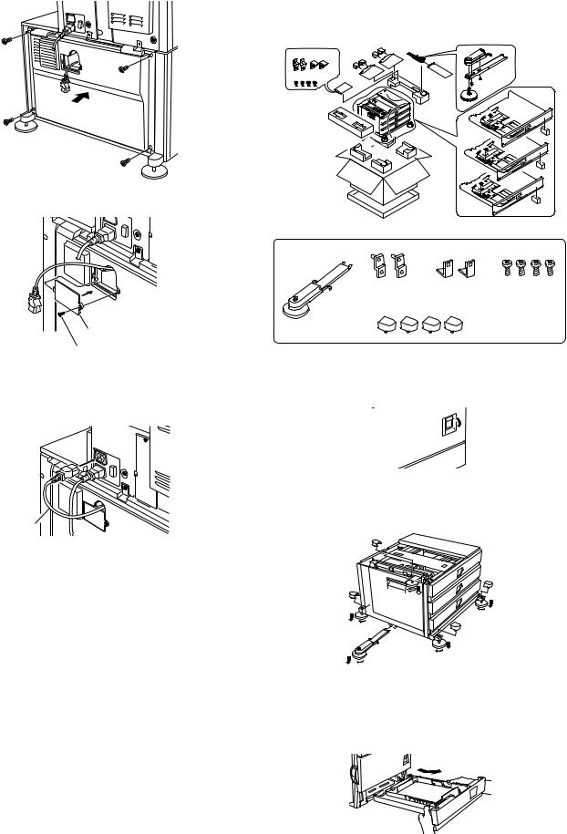
9) Attach the rear cabinet of the stand/paper drawer.
<1>Pass the cord of the power supply unit through the hole of the rear cabinet and attach the rear cabinet to the stand/paper drawer.
Rear cabinet
<2>Attach the AC inlet cover to the rear cabinet of the stand/paper drawer and fix it with the removed screw.
AC inlet cover
Screw
10)Connect the AC cord of the power supply unit to the main unit of the printer.
Connect the AC cord of the power supply unit to the outlet connector of the main unit of the printer at the location shown in the illustration.
AC cord
11)Attach the paper guides to the lower tray (large capacity tray) and set the size.
Refer to "Setting and adjustment" described later.
*If another peripheral device must be installed, carry out the following step at the end of the installation work.
12)Adjust the position of the paper guides of the upper paper tray of the stand/paper drawer.
Refer to "Setting and adjustment" described later.
13)Carry out the off center adjustment.
2.AR-D14
<Before installation>
•Start installation after checking that the DATA and COMMUNICATION indicators on the operation panel are neither lit nor blinking.
•For installation, a power supply unit (AR-DC1) is needed.
<Parts included>
Front mounting |
Rear mounting |
Screws (M4x8): |
plates: 2 pcs. |
plates: 2 pcs. |
4 pcs. |
Left adjuster: 1 pc. |
Adjuster covers: 4 pcs. |
|
1)Turn off the main switch of the main unit of the printer.
Turn the main switch located on the front side of the printer to the "OFF" position.
Then remove the power plug from the outlet.
"OFF"
2) Attach the adjusters and adjust them.
<1>Insert the left adjusters to the stand/paper drawer.
<2>Turn the five adjusters to lower them until they touch the floor. <3>Attach the each adjuster covers.
3 |
|
|
|
|
3 |
3 |
|
|
|
|
2 |
|
|
2 |
2 |
|
3 |
|
|
|
|
1 |
2 |
|
|
*Be sure to attach the left adjuster to prevent overturning.
Caution: The lower tray cannot be pulled out unless the adjuster is lowered to the specified position.
3) Put the main unit of the printer on the stand/paper drawer.
<1>Pull out the paper tray of the main unit until it stops and then remove it by lifting both ends of the tray.
AR-D13/D14/MU1/DC1 UNPACKING AND INSTALLATION 4-3

<2>Hold the main unit of the printer at the positions shown in the illustration and put the main unit on the stand/paper drawer so that the front side and the left side of the main unit are aligned to those of the stand/paper drawer.
Front side
Rear side
Caution: For installation of the main unit, it must be held by two persons and installed without haste.
4) Connect the main unit to the stand/paper drawer.
<1>Attach the rear mounting plates using a supplied screw for each.
Rear mounting plate
Screw Screw
Rear mounting plate
Mounting plate
Desk frame
Caution: Insert the rear mounting plates under the desk frame. <2>Pull out the upper paper tray of the stand/paper drawer until it stops
and attach the front mounting plates using a supplied screw for each. Then, remove the lock of the paper tray and close the tray.
Remove the locks of the middle tray and the lower tray similarly.
Front mounting plate
Screw
Front mounting |
|
plate |
Screw |
<3>Reattach the paper tray of the main unit.
5)Remove the rear cabinet of the stand/paper drawer and remove the AC inlet cover.
<1>Remove the four screws that fix the rear cabinet and then remove the rear cabinet.
Rear cabinet
<2>Remove the screw that fixes the AC inlet cover and then remove the AC inlet cover.
<3>Process the AC inlet cover as shown in the illustration.
Cut out.
AC inlet cover
6)Attach the power supply unit (AR-DC1).
Attach the power supply unit to the hanging portions and secure it using the three supplied screws.
Hanging portion
Hanging portion
Screws
Power supply unit
Screws
AR-D13/D14/MU1/DC1 UNPACKING AND INSTALLATION 4-4
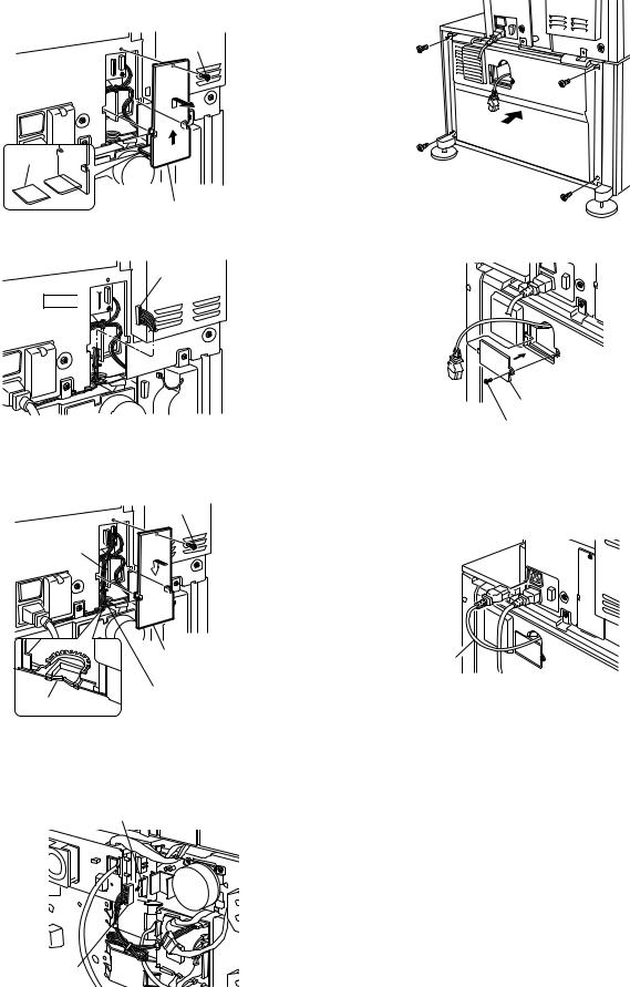
7)Connect the power supply unit harness to the PCU PWB of the main unit of the printer.
<1>Remove the screw that fixes the harness cover of the main unit of the printer and slide the harness cover up to remove it.
Process the harness cover as shown in the illustration.
Screw
Cut out. 
Harness cover
<2>Connect the optional power supply harness connector to CN11 (red connector) of the PCU PWB of the main unit of the printer.
Connector
CN11


<3>Reattach the harness cover to its original position and fix it with the removed screw.
At this time, ensure that the optional power supply unit harness is arranged as shown in the illustration.
•Fix the harness securely to the wire saddle.
Screw
Optional power supply harness
|
Harness cover |
Wire saddle |
Wire saddle |
|
8)Connect the relay harness of the stand/paper drawer to the power supply unit.
Connect the relay harness of the stand/paper drawer to the connector of the power supply unit.
Connector of the power supply connector
Relay harness of the stand/paper drawer
9) Attach the rear cabinet of the stand/paper drawer.
<1>Pass the cord of the power supply unit through the hole of the rear cabinet and attach the rear cabinet to the stand/paper drawer.
Rear cabinet
<2>Attach the AC inlet cover to the rear cabinet of the stand/paper drawer and fix it with the removed screw.
AC inlet cover
Screw
10)Connect the AC cord of the power supply unit to the main unit of the printer.
Connect the AC cord of the power supply unit to the outlet connector of the main unit of the printer at the location shown in the illustration.
AC cord
*If another peripheral device must be installed, carry out the following step at the end of the installation work.
11)Adjust the position of the paper guides of the upper paper tray of the stand/paper drawer.
Refer to "Setting and adjustment" described later.
12)Carry out the off center adjustment.
AR-D13/D14/MU1/DC1 UNPACKING AND INSTALLATION 4-5

3.AR-MU1
<Before installation>
•When installing AR-MU1, if you install a finisher or mail-bin stacker together, a power supply unit (AR-DC1) is needed.
<2>Hold the main unit of the printer at the positions shown in the illustration and put the main unit on the multi purpose drawer so that the front side and the left side of the main unit are aligned to those of the multi purpose drawer.
Front side
Rear side
<Parts included>
Front mounting plates: Rear mounting plates: Screws (M4x8): 2 pcs. 2 pcs. 4 pcs.
1)Turn off the main switch of the main unit of the printer.
Turn the main switch located on the front side of the main unit to the "OFF" position.
Then, remove the power plug of the main unit from the outlet.
Caution: For installation of the main unit, it must be held by two persons and installed without haste.
3) Connect the main unit of the printer to the multi purpose drawer. <1>Attach the rear mounting plates using a supplied screw for each.
 Rear mounting plate
Screw
Screw
Rear mounting plate
Mounting
plate
Tray frame
"OFF"
2) Put the main unit of the printer on the multi purpose drawer. <1>Pull out the paper tray of the main unit until it stops and then remove
it by lifting both ends of the tray.
Caution: Insert the mounting plate under the tray frame.
<2>Pull out the paper tray of the multi purpose drawer until it stops and attach the front mounting plates using a supplied screw for each. Then, remove the lock of the paper tray and close the tray.
Front mounting plate
Screw
Front mounting plate
Screw
<3>Reattach the paper tray of the main unit of the printer.
AR-D13/D14/MU1/DC1 UNPACKING AND INSTALLATION 4-6
4) Connect the harness to the main unit of the printer.
<1>Remove the screw that fixes the harness cover of the main unit of the printer and then slide the harness cover up to remove it.
Process the harness cover as shown in the illustration.
Screw
Cut out.
Harness cover
4.AR-DC1
<Before installation>
•Start installation after checking that the DATA indicator on the operation panel is not lit or blinking.
Parts included
I.T.E.
ACCESSORY 9K11
Screws (3)
1)Turn the main switch of the printer to "OFF".
Turn the main switch located on the front of the printer to "OFF". Then, remove the power plug of the printer from the outlet.
<2>Connect the connector of the relay harness of the multi purpose drawer to the connector of the PCU PWB of the main unit of the printer.
CN10 Connector
*For installation of a finisher or a mail-bin stacker, see its installation manual.
5)Attach the harness cover.
Reattach the harness cover to its original position and fix it with the removed screw.
At this time, ensure that the power supply unit harness is arranged
as shown in the illustration.
•Fix the harness securely to the wire saddle.
Screw
"OFF"
2)Remove the multi rear cabinet.
Remove the two screws that secure the multi rear cabinet and remove the multi rear cabinet.
Screw
Multi rear cabinet
Screw
3)Remove the AC inlet cover from the multi rear cabinet.
Remove the screw that secures the AC inlet cover and remove the AC inlet cover.
Work the AC inlet cover as shown in the illustration.
Cut-out
AC inlet cover
Harness cover
Wire saddle
Wire saddle
*If another peripheral device must be installed, carry out the following step at the end of the installation work.
6)Adjust the position of the paper guides of the paper tray. Refer to "Setting and adjustment" described later.
7)Carry out the off center adjustment.
AR-D13/D14/MU1/DC1 UNPACKING AND INSTALLATION 4-7

4)Attach an optional power supply unit to the multi-purpose section. Attach an optional power supply unit to the positioning portion of the multi-purpose section and secure it with the three screws included in this product.
Screws
Optional power supply unit
Screw
5) Connect the optional power supply harness to the PCU PWB of the printer.
<1>Remove the screw that secures the harness cover of the printer and slide the harness cover upward to remove it.
Work the harness cover as shown in the illustration.
Screw
Cut-out
Harness cover
<2>Connect the connector of the optional power supply harness to CN11 of the PCU PWB of the printer.
Connector
CN11 


<3>Reattach the harness cover to its original position and secure it with the removed screw.
At this time, check that wiring of the optional power supply harness has been handled as shown in the illustration.
Screw
Optional power supply harness
6) Attach the multi rear cabinet.
<1>Pass the AC cord of the optional power supply unit as shown in the illustration and secure the multi rear cabinet with the two screws.
Screw
Multi rear cabinet
AC cord
Screw
<2>Attach the AC inlet cover to the multi rear cabinet and secure it with the removed screw.
Screw |
AC inlet cover |
|
7)Connect the AC cord of the optional power supply unit to the printer. Connect the AC cord of the optional power supply unit to the position of the outlet connector of the printer shown in the illustration.
AC cord
8)Turn the power switch of the printer to "ON". Insert the power plug of the printer to the outlet.
Then, turn the main switch located on the front of the printer to "ON".
"ON"
Harness cover
Harness cover
AR-D13/D14/MU1/DC1 UNPACKING AND INSTALLATION 4-8
[5] EXTERNAL VIEWS AND INTERNAL STRUCTURES
A. External view
|
|
1 |
|
5 |
2 |
|
1 |
3 |
|
|
|
5 |
4 |
|
|
|
|
|
5 |
1 |
|
|
|
|
|
|
|
|
|
|
AR-DU14 |
|
|
AR-DU13 |
|
|
|
AR-MU1 |
1 |
Multi-purpose tray (No. 2 tray) |
2 |
No. 3 tray |
|
3 No. 4 tray |
4 |
Large capacity tray |
5 |
Desk left door |
|
|
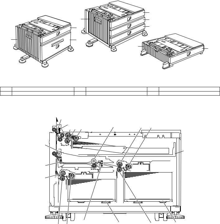
B. Internal structure
(1) AR-D13
4
1.TPFD1 |
8 |
9 |
10 |
|
|
|
|||
5 |
6 |
7 |
|
|
15
 16
16
2.TPFD2
14
|
3.TPFD3 |
17 |
11 |
18 |
|
13 |
12 |
||||
|
|
|
1 |
Tandem tray paper transport sensor 1 (TPFD1) |
7 |
Multipurpose tray paper take-up roller |
13 |
Tandem tray 1 separation roller |
2 |
Tandem tray paper transport sensor 2 (TPFD2) |
8 |
Tandem tray transport roller 2 |
14 |
Tandem tray 1 paper feed roller |
3 |
Tandem tray paper transport sensor 3 (TPFD3) |
9 |
Tandem tray 2 paper feed roller |
15 |
Tandem tray paper transport roller 1 |
4 |
Multipurpose tray paper transport roller |
10 |
Tandem tray 2 paper take-up roller |
16 |
Multipurpose tray |
5 |
Multipurpose tray paper feed roller |
11 |
Tandem tray 2 separation roller |
17 |
Tandem tray 1 |
6 |
Multipurpose tray separation roller |
12 |
Tandem tray 1 take-up roller |
18 |
Tandem tray 2 |
AR-D13/D14/MU1/DC1 EXTERNAL VIEWS AND INTERNAL STRUCTURES 5-1

(2) AR-D14
4 |
|
|
|
|
|
1.DPFD1 |
|
|
|
||
5 |
6 |
7 |
9 |
10 |
11 |
|
|
|
|||
2.DPFD2 |
|
|
|
|
|
8 |
|
|
|
|
16 |
3.DPFD3
17
15
18
14 13 12
1 |
Desk paper transport sensor 1 (DPFD1) |
7 |
Multipurpose tray paper take-up roller |
13 |
Desk tray 3 paper feed roller |
2 |
Desk paper transport sensor 2 (DPFD2) |
8 |
Desk transport roller 2 |
14 |
Desk tray 3 paper feed roller |
3 |
Desk paper transport sensor 3 (DPFD3) |
9 |
Desk tray 2 paper feed roller |
15 |
Desk tray 3 paper transport roller |
4 |
Desk paper transport roller 1 |
10 |
Desk tray 2 paper separation roller |
16 |
Multipurpose tray |
5 |
Multipurpose tray paper feed roller |
11 |
Desk tray 2 take-up roller |
17 |
Desk tray 2 |
6 |
Multipurpose tray separation roller |
12 |
Desk tray 3 take-up roller |
18 |
Desk tray 3 |
(3) AR-MU1
2 1.MCPPD
3 4 5
6
1 |
Multipurpose tray paper transport sensor (MCPPD) |
3 |
Multipurpose tray paper feed roller |
5 |
Multipurpose tray paper take-up roller |
2 |
Multipurpose tray paper transport roller |
4 |
Multipurpose tray separation roller |
6 |
Multipurpose tray |
AR-D13/D14/MU1/DC1 EXTERNAL VIEWS AND INTERNAL STRUCTURES 5-2
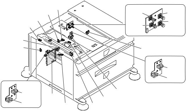
C. PWB, sensor
(1) AR-D13
|
21.MP tray rear edge size PWB |
|
6.MCLUD |
|
|
5.TPFD3 |
7.MCSS1 |
8.MCSS2 |
4.MCSPD |
|
10.MCSS4 |
3.TDRS |
|
|
9.MCSS3 |
|
|
2.TSPD1
1.TPFD2
11.TTSD
|
12.TLUD2 |
|
13.TPED2 |
19.TLUD1 |
14.TSPD2 |
|
|
18. |
15.MCPED |
|
|
20.TPED1 |
16.TPFD1 |
17.MCPWS |
|
Code |
Name |
Function |
Active condition |
Remark |
|
|
|
|
|
|
1 |
TPFD2 |
Tandem tray paper transport sensor 2 |
Tandem tray paper transport detection |
L : Paper detected |
|
|
|
|
|
|
|
2 |
TSPD1 |
Tandem 1 tray |
Tandem 1 tray |
|
|
|
|
remaining paper quantity sensor |
remaining paper quantity detection |
|
|
|
|
|
|
|
|
3 |
TDRS |
Side door open/close sensor |
Side door open/close detection |
H : Door closed |
|
|
|
|
|
|
|
4 |
MCSPD |
MP tray remaining paper quantity sensor |
MP tray remaining paper quantity detection |
|
|
|
|
|
|
|
|
5 |
TPFD3 |
Tandem tray paper transport sensor 3 |
Tandem tray paper transport detection |
L : Paper detected |
|
|
|
|
|
|
|
6 |
MCLUD |
MP tray upper limit sensor |
MP tray upper limit detection |
H : Upper limit |
|
|
|
|
|
detected |
|
|
|
|
|
|
|
7 |
MCSS1 |
MP tray rear edge sensor 1 |
MP tray rear edge size detection |
L : When pressed |
In MP tray rear |
|
|
|
|
|
edge size PWB |
|
|
|
|
|
|
8 |
MCSS2 |
MP tray rear edge sensor 2 |
MP tray rear edge size detection |
L : When pressed |
In MP tray rear |
|
|
|
|
|
edge size PWB |
|
|
|
|
|
|
9 |
MCSS3 |
MP tray rear edge sensor 3 |
MP tray rear edge size detection |
L : When pressed |
In MP tray rear |
|
|
|
|
|
edge size PWB |
|
|
|
|
|
|
10 |
MCSS4 |
MP tray rear edge sensor 4 |
MP tray rear edge size detection |
L : When pressed |
In MP tray rear |
|
|
|
|
|
edge size PWB |
|
|
|
|
|
|
11 |
TTSD |
Tandem tray open/close sensor |
Tandem tray open/close detection |
H : Tray closed |
|
|
|
|
|
|
|
12 |
TLLD2 |
Tandem 2 tray upper limit sensor |
Tandem tray 2 upper limit detection |
L : Upper limit |
|
|
|
|
|
detected |
|
|
|
|
|
|
|
13 |
TPED2 |
Tandem 2 tray paper empty sensor |
Tandem tray 2 paper empty detection |
H : Paper loaded |
|
|
|
|
|
|
|
14 |
TSPD2 |
Tandem 2 tray |
Tandem 2 tray |
|
|
|
|
remaining paper quantity sensor |
remaining paper quantity detection |
|
|
|
|
|
|
|
|
15 |
MCPED |
MP tray paper empty sensor |
MP tray paper empty detection |
L : Paper loaded |
|
|
|
|
|
|
|
16 |
TPFD1 |
Tandem tray paper transport sensor 1 |
Tandem tray paper transport detection |
L : Paper detected |
|
|
|
|
|
|
|
17 |
MCPWS |
MP tray width sensor |
MP tray paper width detection |
|
Slide volume |
|
|
|
|
|
|
18 |
Control PWB |
Control PWB |
Communication with the machine, |
|
|
|
|
|
machine operation control |
|
|
|
|
|
|
|
|
19 |
TLLD1 |
Tandem 1 tray upper limit sensor |
Tandem tray 1 upper limit detection |
L : Upper limit |
|
|
|
|
|
detected |
|
|
|
|
|
|
|
20 |
TPED1 |
Tandem 1 tray paper empty sensor |
Tandem tray 1 paper empty detection |
H : Paper loaded |
|
|
|
|
|
|
|
21 |
MP tray rear |
MP tray rear edge size PWB |
Multi-purpose tray rear edge size detection |
|
|
|
edge size PWB |
|
|
|
|
|
|
|
|
|
|
AR-D13/D14/MU1/DC1 EXTERNAL VIEWS AND INTERNAL STRUCTURES 5-3
 Loading...