


AR-TE3
AR-DU3 |
AR-DU4 |
CODE : 00ZARDU3//A1E
LASER PRINTER OPTIONS
AUTO DUPLEX MODULE
MODEL
AR-DU3 AR-DU4 AR-TE3
CONTENTS
[1] PRODUCT OUTLINE . . . . . . . . . . . . . . . . . . . . . . . . . . . . . . . . 1 - 1
[2] CONFIGURATION. . . . . . . . . . . . . . . . . . . . . . . . . . . . . . . . . . . 2 - 1
[3] SPECIFICATIONS . . . . . . . . . . . . . . . . . . . . . . . . . . . . . . . . . . . 3 - 1
[4] UNPACKING AND INSTALLATION . . . . . . . . . . . . . . . . . . . . . . 4 - 1
[5] EXTERNAL VIEWS AND INTERNAL STRUCTURES . . . . . . . 5 - 1
[6] MACHINE OPERATION . . . . . . . . . . . . . . . . . . . . . . . . . . . . . . 6 - 1
[7] ADJUSTMENTS . . . . . . . . . . . . . . . . . . . . . . . . . . . . . . . . . . . . 7 - 1
[8] DISASSEMBLY AND ASSEMBLY, MAINTENANCE . . . . . . . . . 8 - 1
[9] BLOCK DIAGRAM, WIRING DIAGRAM . . . . . . . . . . . . . . . . . . 9 - 1
Parts marked with “ “ are important for maintaining the safety of the set.
Be sure to replace these parts with specified ones for maintaining the safety and performance of the set.
This document has been published to be used for SHARP CORPORATION after sales service only.
The contents are subject to change without notice.

[1] PRODUCT OUTLINE
This unit is installed to the following machines to serve as a duplex module.
The AR-DU3 is equipped with the duplex feature only, and the AR-DU4 is additionally equipped with the manual paper feed feature. AR-DU3 models is equipped with the paper exit port, which allows installation of the optional paper exit tray, the AR-TE3. (AR-DU4 standard)
Applicable models |
AR-P350 / P450, AR-M350 / M450 |
[2] CONFIGURATION
1.To use this unit, one of the multi purpose paper feed tray (AR-MU1), the 3-stage paper feed desk (AR-D14), and the large capacity paper feed desk (AR-D13) should be installed in advance.
2.When the saddle finisher (AR-FN7) is installed, the duplex module with the manual paper feed feature (AR-DU4) cannot be installed.
3.When the saddle finisher (AR-FN7) is installed, the paper exit tray (AR-TE4) cannot be installed.
Exit tray
(AR-TE3 or AR-DU4 Standard)
Duplex |
Simultaneous installation allowed |
|
B/W scanner module/DSPF(AR-EF1) |
|
|
module/bypass tray |
|
|
(AR-DU4) |
Upper exit tray |
|
|
|
|
|
extension |
|
|
(AR-TE4) |
Finisher |
(AR-FN6)
Duplex module  (AR-DU3)
Mail-bin stacker (AR-MS1)
Saddle stitch finisher (AR-FN7)
Stand/3 x 500 sheet |
Multi purpose drawer |
|
|
(AR-MU1) |
|
|
|
paper drawer |
|
|
|
|
|
|
|
(AR-D14) |
|
|
|
|
|
|
Stand/MPD & 2000 sheet |
|
|
|
paper drawer |
|
|
Power supply unit |
(AR-D13) |
|
|
|
|
Simultaneous installation is required |
(AR-DC1) |
|
|
|
|
||
Related to paper feed unit |
|
B/Wscanner module/DSPF |
Scannerrack |
Multipurpose draw er |
Stand/3x 500 sheet paper dr awer |
Stand/MPD& 2000 sheet |
Duplexmodule/bypass tr ay |
Duplexmodule |
Saddlestitch finisher |
Finisher |
Mail-bin stacker |
Exittray |
Upperexit tray extension |
Punchunit |
Multi-function controller board |
Printserver card |
PS3expansion kit |
Networkscanner expansion kit |
Facsimileexpansion kit Faxmemory (8 MB) |
Powersupply unit |
Harddisk drive |
|
|
|
|
|
|
|
|
|
|
|
|
|
|
|
|
|
|
|
|
|
|
Duplex module/bypass tray |
AR-DU4 |
|
|
|
*1 |
|
|
|
|
|
|
*3 |
|
|
|
|
|
|
|
*2 |
|
|
|
|
|
|
|
|
|
|
|
|
|
|
|
|
|
|
|
|
|
||
Duplex module |
AR-DU3 |
|
|
|
*1 |
|
|
|
|
|
|
|
|
|
|
|
|
|
|
*2 |
|
|
|
|
|
|
|
|
|
|
|
|
|
|
|
|
|
|
|
|
|
||
*1 =Any of the units must be installed together. |
*2 |
=Must be installed for installation of the stand/3 x 500 sheet paper |
|
||||||||||||||||||
drawer or the stand/MPD & 2000 sheet paper drawer. |
|
*3 |
=Standard. |
|
=Cannot be installed together. |
|
|
|
|
||||||||||||
AR-DU3/DU4/TE3 PRODUCT OUTLINE, CONFIGURATION 1-1
[3] SPECIFICATIONS
1. AR-DU3/AR-DU4
A.Basic
|
AR-DU3 |
|
AR-DU4 |
|
|
|
|
Type |
Automatic duplex unit |
|
Automatic duplex unit |
|
|
|
equipped with multi- |
|
|
|
bypass tray and exit |
|
|
|
tray |
|
|
|
|
Transport speed |
To support 35-45 sheet/minute |
||
|
|
|
|
Transport alignment |
Center alignment |
|
|
|
|
|
|
Power consumption |
Less than about 25W |
|
Less than about 46.6W |
|
|
|
|
Power source |
Supplied from main unit |
|
|
|
|
|
|
External |
115x412x416 (mm) |
|
451x439x416 (mm) |
dimensions(WxDxH)* |
|
|
|
|
|
|
|
Occupied |
115x412 (mm) |
|
451x439 (mm) |
dimensions(WxD) |
|
|
|
|
|
|
|
Weight |
Approx. 5kg |
|
Approx. 7.5kg |
|
|
|
|
AR-DU4: When the tray is extended fully.
AR-DU3: The AR-TE3 is not installed.
B.Duplex part
Method |
Non-stack method |
Paper size |
A3, B4, A4, A4R, B5, B5R, A5R |
|
11"x17", 8.5"x14", 8.5"x13", 8.5"x11", |
|
8.5"x11"R, 5.5"x8.5"R |
Media for paper transfer |
Plain 60-105g/m² / 15-28lbs |
C.Exit tray (AR-TE3, AR-DU4)
Output paper capacity |
100 sheets (A4/8.5"x11" 80g/m²) |
|
|
Output paper delivery |
Face-down |
|
|
Output paper size |
A3, B4, A4, A4R, B5, B5R, A5R |
|
|
|
11"x17", 8.5"x14", 8.5"x13", 8.5"x11", |
||
|
8.5"x11"R, 5.5"x8.5"R, |
|
|
|
Executive |
|
|
Media for paper output |
Plain paper |
60-105g/m² / |
16-28lbs |
|
Heavy paper |
106-205g/m² |
/ 29-55lbs |
|
Transparency film |
|
|
Remaining paper |
Not provided |
|
|
detection |
|
|
|
Exit tray full detection |
Not provided |
|
|
D.Multi-bypass tray part (AR-DU4 only)
Paper size |
A3, B4, A4, A4R, B5, B5R, A5R |
||
|
11"x17", 8.5"x14", 8.5"x13", 8.5"x11", |
||
|
8.5"x11"R, 5.5"x8.5"R, |
|
|
|
Executive, Japanese p/c |
|
|
Media available for paper |
Tracing paper |
52-59g/m² / 14 ~ 15lbs |
|
feeding |
|
(only single feed) |
|
|
Plain paper |
60-128g/m² / 16 ~ 34lbs |
|
|
Indea paper |
176g/m² |
/ 47lbs |
|
Cover paper |
205g/m² |
/ 54 ~ 55lbs |
|
Transparency |
|
|
|
* Media heavier than 105g/m² should be |
||
|
A4/8.5x11" or smaller. Media heavier than |
||
|
108g/m² should be fed from shorter edge. |
||
|
* Only single paper feed is enabled for |
||
|
overlay copy or copy on back-side of |
||
|
printed paper. |
|
|
Paper capacity |
100 sheets |
|
|
|
(standard paper:80g/m²) |
|
|
|
Post card: 20 sheets |
|
|
|
Transparency film: 20 sheets |
||
Paper type |
Plain, recycled, pre-printed, pre-punched, |
||
|
color, letter head, labels, heavy, |
||
|
transparency, Japanese p/c, envelope |
||
|
(User can set bi-type for each of the above |
||
|
paper type.) |
|
|
Paper size detection |
Automatic-AB |
A3, B4, A4, A4R, B5, B5R, |
|
|
(200V system) |
8.5" ~ 13", A5R |
|
|
Automatic-inch |
11"x17", 8.5"x14", |
|
|
(100V system) |
8.5"x13", 8.5"x11", |
|
|
|
8.5"x11"R, 7.25"x 10.5 R, |
|
|
|
5.5"x 8.5" |
|
|
Manual |
Post card |
|
Detection ignoring setting |
Provided |
|
|
Remaining paper detection |
Not provided |
|
|
AR-DU3/DU4/TE3 SPECIFICATIONS 3-1
[4] UNPACKING AND INSTALLATION
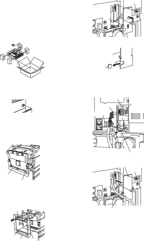
1.AR-DU3
<Before installation>
•Carry out the installation after checking that the DATA indicator on the operation panel is neither lit nor blinking.
•For installing AR-DU3, an optional desk (multi purpose drawer, stand/3 x 500 sheet paper drawer or stand/MPD & 2000 sheet drawer) must have been installed.
•Ensure that the front mounting plates and the rear mounting plates included with the optional stand/paper drawer are securely attached.
•Check that the left adjuster supplied with an optional stand/drawer has been attached.
1)Turn off the main switch of the main unit of the printer.
Turn the main switch located on the front side of the main unit of the printer to the "OFF" position.
Then, remove the power plug of the main unit of the printer from the outlet.
"OFF"
2)Remove the left side cover of the main unit of the printer.
Unlock the lock release lever of the main unit of the printer and then pull out the left door.
Slide the two upper covers up to remove them. Remove the lower cover by inserting a flat-blade screwdriver at three locations (  ) shown in the illustration.
Then, close the left door.
Top covers
Left door
Lower cover
Lock release lever
3) Attach the duplex module to the main unit of the printer.
<1>Hang the hooks located at the upper part of the duplex module on the openings of the left door of the main unit of the printer.
<2>Push the lower part of the duplex module to insert the positioning bosses securely into the main unit of the printer.
<3>Tighten the two screws built in the duplex module.
Hook |
1 |
Hook |
|
1 |
|||
|
|
3
3
2
 2
2
Positioning boss
Duplex module Positioning boss
4) Connect the harness to the main unit of the printer.
<1>Remove the screw that fixes the harness cover of the main unit of the printer and then slide the harness cover up to remove it.
Screw
Harness cover
<2>Process the harness cover as shown in the illustration.
Harness cover
Cut out.
<3>Connect the connector of the relay harness of the duplex module to the CN12 (white connector) of the PCU PWB of the main unit of the printer.
<4>Insert the snap bands to the locations shown in the illustration and fix them.
<5>Secure the earth harness using a supplied M4 screw.
CN12
PCU PWB
Relay harness
connector
3
Snap bands
4
4 
5
Screw
Ground harness
<6>Reattach the harness cover to its original position and fix it with the removed screw.
Harness cover
Screw
Relay harness
*If another peripheral device must be installed, carry out the following step at the end of the installation work.
5) Carry out the off center adjustment.
AR-DU3/DU4/TE3 UNPACKING AND INSTALLATION 4-1

2.AR-DU4
<Before installation>
•Carry out the installation after checking that the DATA indicator on the operation panel is neither lit nor blinking.
•For installing AR-DU4, an optional desk (multi purpose drawer, stand/3 x 500 sheet paper drawer or stand/MPD & 2000 sheet drawer) must have been installed.
•Ensure that the front mounting plates and the rear mounting plates included with the optional stand/paper drawer are securely attached.
•Check that the left adjuster supplied with an optional stand/drawer has been attached.
Parts included
Exit tray
1)Turn off the main switch of the main unit of the printer.
Turn the main switch located on the front side of the main unit of the printer to the "OFF" position.
Then, remove the power plug of the main unit of the printer from the outlet. 
"OFF"
2)Remove the left side cover of the main unit of the printer.
Unlock the lock release lever of the main unit of the printer and then pull out the left door.
Slide the two upper covers up to remove them. Remove the lower cover by inserting a flat-blade screwdriver at three locations (  ) shown in the illustration.
Then, close the left door.
Top covers |
|
||
Left door |
|
||
Lower cover |
|
|
|
Lock release lever |
|
||
3) Attach the duplex module to the main unit of the printer. |
|||
<1>Hang the hooks located at the upper part of the duplex module on |
|||
the openings of the left door of the main unit of the printer. |
|||
<2>Push the lower part of the duplex module to insert the positioning |
|||
bosses securely into the main unit of the printer. |
|||
<3>Tighten the two screws built in the duplex module. |
|||
Hook |
1 |
Hook |
|
1 |
|||
|
|||
3
3
2
 2
2
Positioning boss
Duplex module Positioning boss
4) Connect the harness to the main unit of the printer.
<1>Remove the screw that fixes the harness cover of the main unit of the printer and then slide the harness cover up to remove it.
Screw
Harness cover
<2>Process the harness cover as shown in the illustration.
Harness cover
Cut out.
<3>Connect the connector of the relay harness of the duplex module to the CN12 (white connector) of the PCU PWB of the main unit of the printer.
<4>Insert the two snap bands to the locations shown in the illustration and fix them.
<5>Secure the earth harness using a supplied M4 screw.
CN12
PCU PWB
Relay harness
connector
3
Snap bands
4
4 
 5
5
Screw
Ground harness
<6>Reattach the harness cover to its original position and fix it with the removed screw.
Harness cover
Screw
Relay harness
5) Attach the exit tray.
*If another peripheral device must be installed, carry out the following step at the end of the installation work.
6)Adjust the position of the paper guides of the bypass tray. Refer to "Adjustments" described later.
7)Carry out the off center adjustment.
AR-DU3/DU4/TE3 UNPACKING AND INSTALLATION 4-2

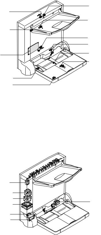
[5] EXTERNAL VIEWS AND INTERNAL STRUCTURES
A. External view
1
3
42
1 |
Paper exit tray (AR-TE3, AR-DU4 standard) |
2 |
Manual paper feed tray (AR-DU4 only) |
3 |
Paper feed module side cover |
4 |
Manual paper fed extension tray |
|
|
|
|
B. Internal structure
|
1 |
2.APIND |
13.APOD 14 |
|
|
|
|
|
3.APPD1 |
12 |
|
11 |
|
10 |
|
9.MPED |
4.APPD2 |
|
|
8 |
|
|
|
|
7 |
6 |
5 |
|
|
|
|
|
|
|
|
|
|
1 |
ADU paper entry roller |
6 |
Separation pad |
|
|
11 |
ADU transport roller 1 |
2 |
ADU paper entry sensor (APIND) |
7 |
Manual paper feed roller |
|
|
12 |
ADU paper exit roller |
3 |
ADU transport sensor 1 (APPD1) |
8 |
Manual take-up roller |
|
|
13 |
ADU paper exit sensor (APOD) |
4 |
ADU transport sensor 2 (APPD2) |
9 |
Manual feed paper sensor (MPED) |
|
14 |
ADU paper exit gate |
|
5 |
ADU transport roller 3 |
10 |
ADU transport roller 2 |
|
|
|
|
AR-DU3/DU4/TE3 EXTERNAL VIEWS AND INTERNAL STRUCTURES 5-1
C. PWB, sensor
4. APIND
3. DSW-D
1.
11. MPLS2
10. MPLS1
2. APOD
5. APPD1
6. APPD2
7. MPED
9. MPWS
8. MPLD1 |
|
Code |
Name |
Function |
Active condition |
Remark |
|
|
|
|
|
|
1 |
ADU drive PWB |
ADU drive PWB |
Communication with the machine, ADU drive, control |
|
|
|
|
|
|
|
|
2 |
APOD |
ADU paper exit sensor |
Paper exit detection |
L : Paper loaded |
|
|
|
|
|
|
|
3 |
DSW-D |
ADU door sensor |
Door open detection |
L : Open |
|
|
|
|
|
|
|
4 |
APND |
ADU paper entry sensor |
Paper feed detection |
L : Paper loaded |
|
|
|
|
|
|
|
5 |
APPD1 |
ADU transport sensor 1 |
Paper transport detection |
L : Paper loaded |
|
|
|
|
|
|
|
6 |
APPD2 |
ADU transport sensor 2 |
Paper transport detection |
L : Paper loaded |
|
|
|
|
|
|
|
7 |
MPED |
Manual feed paper sensor |
Manual feed tray paper empty detection |
L : Paper loaded |
AR-DU4 only |
|
|
|
|
|
|
8 |
MPLD1 |
Manual feed paper length sensor |
Manual feed tray paper length detection |
H : Paper loaded |
AR-DU4 only |
|
|
|
|
|
|
9 |
MPWS |
Manual feed paper width sensor |
Manual feed tray paper width detection |
|
AR-DU4 only |
|
|
|
|
|
|
10 |
MPLS1 |
Tray pull-out sensor |
Manual feed extension tray pull-out detection |
H: Pulled out |
AR-DU4 only |
|
|
|
|
|
|
11 |
MPLS2 |
Tray installation sensor |
Manual feed extension tray installation detection |
H: Pushed in |
AR-DU4 only |
|
|
|
|
|
|
D. Motor, clutch, solenoid
4.DGS
1.SPM_HI
2.SPM_LO
7. MSS
3. ADUFM
5.MPFC
6.MPFS
|
Code |
Name |
Function |
Remark |
|
|
|
|
|
1 |
SPM_HI |
Upper transport motor |
Upper section paper transport |
|
|
|
|
|
|
2 |
SPM_LO |
Lower transport motor |
Lower section paper transport |
|
|
|
|
|
|
3 |
ADUFM |
Cooling fan motor |
Cooling the ADU |
|
|
|
|
|
|
4 |
DGS |
Gate solenoid upper |
Gate select in duplex copy, paper exit |
|
|
|
|
|
|
5 |
MPFC |
Manual paper feed clutch |
Paper feed clutch from the manual paper feed tray |
AR-DU4 only |
|
|
|
|
|
6 |
MPFS |
Manual paper feed solenoid |
Paper feed solenoid from the manual paper feed tray |
AR-DU4 only |
|
|
|
|
|
7 |
MSS |
Shutter solenoid |
Shutter open/close in manual paper feed |
AR-DU4 only |
|
|
|
|
|
AR-DU3/DU4/TE3 EXTERNAL VIEWS AND INTERNAL STRUCTURES 5-2
[6] MACHINE OPERATION
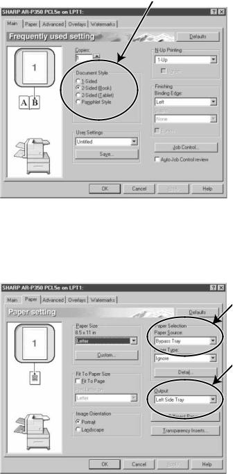
1.Setting the printer driver for duplex module, bypass tray and exit tray
When using the duplex module (including the bypass tray and the exit tray) for printing, select "Properties" and make selections as follows for the print job.
*The screens used in the following descriptions are for a PCL driver in the Windows 98 environment.
A. Two-sided printing
Open the "Main" tab and check the radio button of the desired two-sided printing mode.
B. Using the bypass tray
Open the "Paper" tab shown in the illustration below and select "Bypass Tray" in the "Paper Selection" drop down.
C. Using the exit tray mounted to the duplex module
Open the "Paper" tab shown in the illustration below and select "Left Side Tray" in the "Output" drop down.
Note:The settings screens above will appear only if the devices have been set properly in the printer driver configuration
2. Copying in the duplex mode
For copying in the duplex mode, press the COPY key on the operation panel and make all selections on the copy mode basic screen.
A. Automatic duplex copying
Touch the [2-SIDED COPY] key on the copy mode basic screen. A selection screen for two-sided copying will appear.
B.Using the bypass tray
Touch the [PAPER SELECT] key on the copy mode basic screen.
A selection screen for paper source will appear. Select the bypass tray on this screen.
C. Using the exit tray
Touch the [OUTPUT] key on the copy mode basic screen.
A selection screen for output will appear. Select the exit tray mounted to the duplex module on this screen.
AR-DU3/DU4/TE3 MACHINE OPERATION 6-1
 Loading...