


Schneider Electric Altivar212 User Manual

www.schneider-electric.com
Altivar 212
Variable speed drives for asynchronous motors
LONWORKS
®
communication manual
VW3 A21 212
01/2011
S1A53848

2 S1A53848 01/2011
The information provided in this documentation contains general descriptions and/or technical characteristics
of the performance of the products contained herein. This documentation is not intended as a substitute for
and is not to be used for determining suitability or reliability of these products for specific user applications. It
is the duty of any such user or integrator to perform the appropriate and complete risk analysis, evaluation and
testing of the products with respect to the relevant specific application or use thereof. Neither Schneider
Electric nor any of its affiliates or subsidiaries shall be responsible or liable for misuse of the information
contained herein. If you have any suggestions for improvements or amendments or have found errors in this
publication, please notify us.
No part of this document may be reproduced in any form or by any means, electronic or mechanical, including
photocopying, without express written permission of Schneider Electric.
All pertinent state, regional, and local safety regulations must be observed when installing and using this
product. For reasons of safety and to help ensure compliance with documented system data, only the
manufacturer should perform repairs to components.
When devices are used for applications with technical safety requirements, the relevant instructions must be
followed.
Failure to use Schneider Electric software or approved software with our hardware products may result in
injury, harm, or improper operating results.
Failure to observe this information can result in injury or equipment damage.
© 2011 Schneider Electric. All rights reserved.

S1A53848 01/2011 3
Table of Contents
Safety Information . . . . . . . . . . . . . . . . . . . . . . . . . . . . . . . . . . . . . . . . . . . . . . . . . . . . . . . . . . . . . . . . . . . 5
About the Book . . . . . . . . . . . . . . . . . . . . . . . . . . . . . . . . . . . . . . . . . . . . . . . . . . . . . . . . . . . . . . . . . . . . . 6
Chapter 1 Introduction. . . . . . . . . . . . . . . . . . . . . . . . . . . . . . . . . . . . . . . . . . . . . . . . . . . . . . . . . . . 9
Chapter 2 Hardware setup. . . . . . . . . . . . . . . . . . . . . . . . . . . . . . . . . . . . . . . . . . . . . . . . . . . . . . . 11
Receipt . . . . . . . . . . . . . . . . . . . . . . . . . . . . . . . . . . . . . . . . . . . . . . . . . . . . . . . . . . . . . 12
Opening the drive . . . . . . . . . . . . . . . . . . . . . . . . . . . . . . . . . . . . . . . . . . . . . . . . . . . . . 13
Installing the LonWorks communication card in ATV212 . . . . . . . . . . . . . . . . . . . . . . . 15
Hardware description . . . . . . . . . . . . . . . . . . . . . . . . . . . . . . . . . . . . . . . . . . . . . . . . . . 16
Use of open Style Connector . . . . . . . . . . . . . . . . . . . . . . . . . . . . . . . . . . . . . . . . . . . . 16
Description of terminals . . . . . . . . . . . . . . . . . . . . . . . . . . . . . . . . . . . . . . . . . . . . . . . . 17
Chapter 3 Connecting to the bus . . . . . . . . . . . . . . . . . . . . . . . . . . . . . . . . . . . . . . . . . . . . . . . . .19
Topology. . . . . . . . . . . . . . . . . . . . . . . . . . . . . . . . . . . . . . . . . . . . . . . . . . . . . . . . . . . . 20
Cable routing practices. . . . . . . . . . . . . . . . . . . . . . . . . . . . . . . . . . . . . . . . . . . . . . . . . 21
Connecting the LonWorks connector . . . . . . . . . . . . . . . . . . . . . . . . . . . . . . . . . . . . . . 22
Chapter 4 Configuration . . . . . . . . . . . . . . . . . . . . . . . . . . . . . . . . . . . . . . . . . . . . . . . . . . . . . . . . 23
Communication parameters . . . . . . . . . . . . . . . . . . . . . . . . . . . . . . . . . . . . . . . . . . . . . 24
Configuration of the control . . . . . . . . . . . . . . . . . . . . . . . . . . . . . . . . . . . . . . . . . . . . . 26
Configuring the behaviour on configuration interruption. . . . . . . . . . . . . . . . . . . . . . . . 31
Chapter 5 Diagnostics . . . . . . . . . . . . . . . . . . . . . . . . . . . . . . . . . . . . . . . . . . . . . . . . . . . . . . . . . . 33
Communication detected fault . . . . . . . . . . . . . . . . . . . . . . . . . . . . . . . . . . . . . . . . . . . 34
List of type supported by ATV212 Service LED . . . . . . . . . . . . . . . . . . . . . . . . . . . . . . 35
Troubleshooting . . . . . . . . . . . . . . . . . . . . . . . . . . . . . . . . . . . . . . . . . . . . . . . . . . . . . . 36
Chapter 6 Functional profile . . . . . . . . . . . . . . . . . . . . . . . . . . . . . . . . . . . . . . . . . . . . . . . . . . . . . 37
Objects supported . . . . . . . . . . . . . . . . . . . . . . . . . . . . . . . . . . . . . . . . . . . . . . . . . . . . 38
LonMark Node Object profile . . . . . . . . . . . . . . . . . . . . . . . . . . . . . . . . . . . . . . . . . . . . 38
LonMark Variable Speed Motor Drive profile . . . . . . . . . . . . . . . . . . . . . . . . . . . . . . . . 39
Chapter 7 Network variables and configuration properties. . . . . . . . . . . . . . . . . . . . . . . . . . . . 41
List of network variables and configuration properties . . . . . . . . . . . . . . . . . . . . . . . . . 42
Commands and setpoints. . . . . . . . . . . . . . . . . . . . . . . . . . . . . . . . . . . . . . . . . . . . . . . 44
Status and output velocity . . . . . . . . . . . . . . . . . . . . . . . . . . . . . . . . . . . . . . . . . . . . . . 48
Alarms . . . . . . . . . . . . . . . . . . . . . . . . . . . . . . . . . . . . . . . . . . . . . . . . . . . . . . . . . . . . . 51
Measurements . . . . . . . . . . . . . . . . . . . . . . . . . . . . . . . . . . . . . . . . . . . . . . . . . . . . . . . 52
Monitoring of digital inputs . . . . . . . . . . . . . . . . . . . . . . . . . . . . . . . . . . . . . . . . . . . . . . 53
Monitoring of analog inputs . . . . . . . . . . . . . . . . . . . . . . . . . . . . . . . . . . . . . . . . . . . . . 53
Control of digital outputs. . . . . . . . . . . . . . . . . . . . . . . . . . . . . . . . . . . . . . . . . . . . . . . . 53
Emergency . . . . . . . . . . . . . . . . . . . . . . . . . . . . . . . . . . . . . . . . . . . . . . . . . . . . . . . . . . 54
Adjustment . . . . . . . . . . . . . . . . . . . . . . . . . . . . . . . . . . . . . . . . . . . . . . . . . . . . . . . . . . 55
Parameter access. . . . . . . . . . . . . . . . . . . . . . . . . . . . . . . . . . . . . . . . . . . . . . . . . . . . . 58
Identification . . . . . . . . . . . . . . . . . . . . . . . . . . . . . . . . . . . . . . . . . . . . . . . . . . . . . . . . . 60
Network management . . . . . . . . . . . . . . . . . . . . . . . . . . . . . . . . . . . . . . . . . . . . . . . . . 61
Table of Contents

Table of Contents
4 S1A53848 01/2011

S1A53848 01/2011 5
§
Safety Information
Safety Information
Important Information
NOTICE
Read these instructions carefully, and look at the equipment to become familiar with the device before trying
to install, operate, or maintain it. The following special messages may appear throughout this documentation
or on the equipment to warn of potential hazards or to call attention to information that clarifies or simplifies a
procedure.
PLEASE NOTE
The word “drive” as used in this manual refers to the controller portion of the adjustable speed drive as defined
by NEC.
Electrical equipment should be installed, operated, serviced, and maintained only by qualified personnel. No
responsibility is assumed by Schneider Electric for any consequences arising out of the use of this material.
The addition of this symbol to a Danger or Warning safety label indicates that an electrical hazard
exists, which will result in personal injury if the instructions are not followed.
This is the safety alert symbol. It is used to alert you to potential personal injury hazards. Obey all
safety message that follow this symbol to avoid possible injury or death.
DANGER
DANGER indicates an imminently hazardous situation, which, if not avoided, will result in death or serious
injury.
WARNING
WARNING indicates a potentially hazardous situation, which, if not avoided, can result in death, serious
injury or equipment damage.
CAUTION
CAUTION indicates a potentially hazardous situation, which, if not avoided, can result in injury or equipment
damage.
CAUTION
CAUTION, used without the safety alert symbol, indicates a potentially hazardous situation which, if not
avoided, can result in equipment damage.

6 S1A53848 01/2011
About the Book
About the Book
At a Glance
Document Scope
The purpose of this document is to:
• install the card in the drive,
• show you how to configure the Altivar 212 to use LONWORKS
®
for monitoring and control.
NOTE: Read and understand this document and all related documents (see below) before installing,
operating, or maintaining your ATV212.
Validity Note
This documentation is valid for the Altivar 212 L
ONWORKS fieldbus.
Related Documents
You can download the latest versions of these technical publications and other technical information on
www.schneider-electric.com.
Product Related Information
Title of Documentation Reference Number
ATV212 Quick Start S1A53825
ATV212 Installation manual S1A53832
ATV212 Programming manual S1A53838
ATV212 Modbus manual S1A53844
ATV212 Metasys N2 manual S1A53846
ATV212 Apogée FLN P1 manual S1A53847
ATV212 BACnet manual S1A53845
ATV212 other option manuals: see www.schneider-electric.com
DANGER
UNINTENDED EQUIPMENT OPERATION
• Read and understand this manual before installing or operating the Altivar 212 drive.
• Any changes made to the parameter settings must be performed by qualified personnel.
Failure to follow these instructions will result in death or serious injury.
About the Book
S1A53848 01/2011 7
(1) For additional information, refer to NEMA ICS 1.1 (latest edition), “Safety Guidelines for the Application, Installation, and
Maintenance of Solid State Control” and to NEMA ICS 7.1 (latest edition), “Safety Standards for Construction and Guide
for Selection, Installation and Operation of Adjustable-Speed Drive Systems.”
DANGER
HAZARD OF ELECTRIC SHOCK, EXPLOSION OR ARC FLASH
• Read and understand this manual before installing or operating the drive. Installation, adjustment, repair,
and maintenance must be performed by qualified personnel.
• The user is responsible for compliance with all international and national electrical code requirements with
respect to grounding of all equipment.
• Many parts of this drive, including the printed circuit boards, operate at the line voltage. DO NOT TOUCH.
Use only electrically insulated tools.
• DO NOT touch unshielded components or terminal strip screw connections with voltage present.
• DO NOT short across terminals PA/+ and PC/– or across the DC bus capacitors.
• Before servicing the drive:
- Disconnect all power, including external control power that may be present.
- Place a “DO NOT TURN ON” label on all power disconnects.
- Lock all power disconnects in the open position.
- WAIT 15 MINUTES to allow the DC bus capacitors to discharge.
- Measure the voltage of the DC bus between the PA/+ and PC/– terminals to ensure that the voltage is
less than 42 Vdc.
- If the DC bus capacitors do not discharge completely, contact your local Schneider Electric
representative. Do not repair or operate the drive
• Install and close all covers before applying power or starting and stopping the drive.
Failure to follow these instructions will result in death or serious injury.
WARNING
DAMAGE DRIVE EQUIPMENT
Do not operate or install any drive or drive accessory that appears damaged.
Failure to follow these instructions can result in death, serious injury, or equipment damage.
WARNING
LOSS OF CONTROL
• The designer of any control scheme must consider the potential failure modes of control paths and, for
certain critical control functions, provide a means to achieve a safe state during and after a path failure.
Examples of critical control functions are emergency stop and overtravel stop.
• Separate or redundant control paths must be provided for critical control functions.
• System control paths may include communication links. Consideration must be given to the implications
of unanticipated transmission delays or failures of the link (1).
Failure to follow these instructions can result in death, serious injury, or equipment damage.

About the Book
8 S1A53848 01/2011

S1A53848 01/2011 9
Introduction
1
Introduction
Thank you for purchasing the LONWORKS
®
option card (VW3 A21 212) for Altivar 212 drive.
By installing this card into the Altivar 212, data communication can be made with a host computer or other
device via LONWORKS
®
network.
The communication card has an open-style 3-pin connector for connection to the network. It supports free
topology (TP/FT-10) at 78 kbit/s.
Data exchanges give access to all Altivar 212 functions:
• Control (start, stop, reset, setpoint),
• Monitoring (status, current, voltage, thermal state...),
• Diagnostics (alarms).
The L
ONWORKS resource files (.XIF...) that provide the network configuration tools (LonMaker
®
...) with device
information are available on www.schneider-electric.com.
LONWORKS
®
, LONMARK
®
, LonMaker
®
, Neuron are trademarks of Echelon Corporation registered in the United
States and other countries.
LONMARK
®
and LONMARK
®
Logo are managed, granted, and used by LONMARK
®
International under a license
granted by Echelon Corporation.

Introduction
10 S1A53848 01/2011

S1A53848 01/2011 11
Hardware setup
2
Hardware setup
What's in this Chapter?
This chapter contains the following topics:
Topic Page
Receipt 12
Opening the drive 13
Hardware description 16
Use of open Style Connector 16
Description of terminals 17

Hardware setup
12 S1A53848 01/2011
Receipt
•
Check that the card reference printed on the label is the same as that on the delivery note corresponding
to the purchase order.
• Remove the option card from its packaging and check that it has not been damaged in transit.
• The LONWORKS card is shipped together with the following accessories. On opening the packing case,
check to see if the following accessories are contained or not.
- 1 cabling label,
- 3 neuron ID labels (barcode EAN128),
- 1 screw.
Hardware setup
S1A53848 01/2011 13
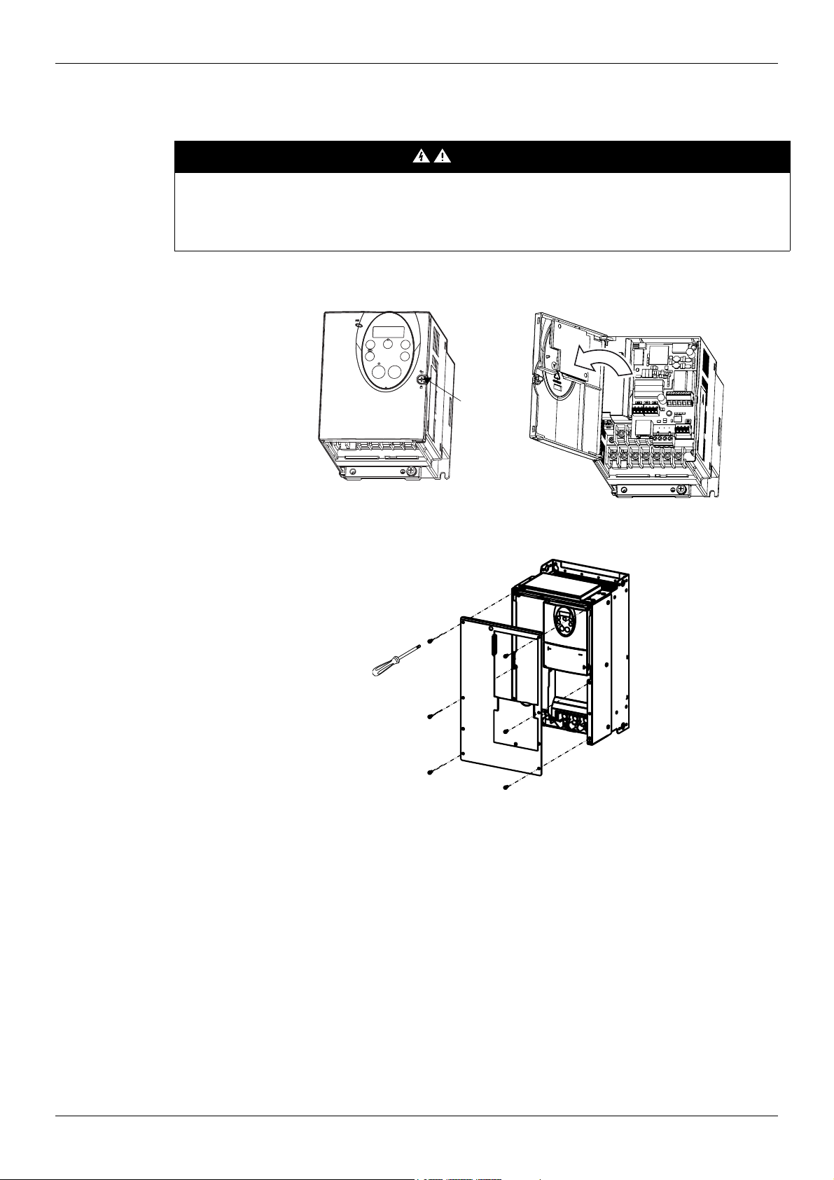
Opening the drive
1 Any procedure in this section must be performed when product is powered off.
2 Open the ATV212 front cover.
DANGER
HAZARD OF ELECTRIC SHOCK, EXPLOSION OR ARC FLASH
Read and understand the instructions in "About the book" chapter, before performing the procedure in this
section.
Failure to follow these instructions will result in death or serious injury.
ATV212H products up to 22 kW .
Turn the screw on the
front panel 90°
counter-clockwise to
align the dot on the
screw with the unlock
position.
To avoid damaging
the screw, do not
apply excessive force
or turn the screw more
than 90°.
ATV212H products from 22 kW
Remove the screws.
Lift off the cover.
Pull the front panel toward you
and swing it open to the left
Screw

Hardware setup
14 S1A53848 01/2011
ATV212W up to 7.5 kW ATV212W above 7.5 kW

Hardware setup
S1A53848 01/2011 15
Installing the LONWORKS communication card in ATV212
Note: To install or remove the terminal board, make it slide in or out in parallel with board.
DANGER
UNINTENDED EQUIPMENT OPERATION
z Do not plug or unplug the terminal board while drive is powered.
z Check the tightening of the mounting screw after any manipulation on the terminal board.
Failure to follow these instructions will result in death or serious injury.
1 Open the ATV212 front cover,
remove the terminal board
mounting screw and take off the
ATV212 standard terminal board.
See paragraph How to open the
front cover, page 13
. Be careful
not to lose the terminal board
mounting screw when removed
since it may be used again. On
drives from 0.75 to 2.2 kW the
board features a plastic tag to
hold the mounting screw in place.
2 Make the power and control
wiring connections before
installing communication card.
3 Install the L
ONWORKS
communication card. Fit the
board mounting screw (M3
tapping type) and tighten to 0.7 to
0.8 Nm
4 Stick the cabling label for
communication card on the
standard cabling label stuck on
front cover (internal side)
ATV212. And stick the
communication card nameplate
close to the standard nameplate.
Be careful not to cover slits on
the ATV212 enclosure.
B
A
GND
SCR
PLC
VIA
U
VIB
U
I
PT
C
SW1
00
Sin
k
PL
C
S
ou
r
c
e
SW1
02
I
U
SW101
T
e
r
m
SW1
03
PLC
VIA U
VIB U
I
P
T
C
SW100
Sink
P
LC
S
ou
r
ce
SW102
I
U
SW101
T
e
r
m
SW103
P24M
NETASHLD NETB
G/E
ON ORKS
R
L
W
S1A58023
VIB
Sink
PTC
Source
SW100 SW200
VW3A21212
SERVICE LED
SERVICE SW

Hardware setup
16 S1A53848 01/2011
Hardware description
Use of open Style Connector
General
Use the open style connector to connect the drive to L
ONWORKS fieldbus. Connection details are given in the
"Connecting to the bus" section page 19
.
CC
G/E FLA
RJ45
FLB
FLC
FR
RES
NETA
NETB
SHLD
VIB PP
P24M
LONWORKS OpenStyle connector
Selector switch SW100
- VIB function
(VIB/PTC)
- Logic for F, R, RES terminal
(SINK/SOURCE)
RJ45 port
Service LED
Terminal board
mounting screw
hole (M3 screw)
Connector to drive
VIB
SINK
PTC
SOURCE
SW200 (1)
Commissioning button
(1) The SW200 switch enables to send the network address to the master.
DANGER
UNINTENDED EQUIPMENT OPERATION
• Modify only the setting of the switches when the product is switched off.
• Do not change the setting of the SW100 unless your system is wired for SINK logic.
Failure to follow these instructions will result in death or serious injury.
CAUTION
RISK OF BODY INJURY
Use a screwdriver to change the position of the switches.
Failure to follow these instructions can result in injury or equipment damage.

Hardware setup
S1A53848 01/2011 17
Description of terminals
(1) Voltage conversion
(2) PTC (Positive Temperature Coefficient): Resettable thermal fuse resistor for over current protection.
Terminal
symbol
Function Electrical specifications Internal circuits
CC Control circuit equipotential terminal -
-
VIB
Multifunction programmable analog
input. It has speed setpoint function in
the default setting (0 to 50 Hz
frequency with 0 to 10 Vdc input). In
addition, this terminal can be used as
PTC (2) input by setting switch SW100
and the parameters [Mot PTC
selection] F645 and [PTC resistor
value] F646.
Voltage: 10 Vdc
Internal impedance: 30 kΩ
PP
Voltage supply for reference
potentiometer.
Voltage: 10 Vdc
Max current: 10 mA
Protected against short
circuits.
F
Multifunctional programmable logic
input.
It has forward rotation function in
default setting.
ON: forward rotation drive
OFF: slowdown and stop
No voltage contact input
24 Vdc
5 mA or less.
SINK/SOURCE can be
selected with SW100.
R
Multifunctional programmable logic
input. It has Preset speed 1 in default
setting.
RES
Multifunctional programmable logic
input. It has Fault Reset in default
setting
P24M 24 VDC power supply output
24 Vdc
50 mA
NETA
L
ONWORKS transmission data /
reception data.
No polarity.
SHLD
L
ONWORKS communication shield
terminal.
This terminal is not connected
to any other circuit of the card.
Ground this terminal in a
location separated from the
ground of power line.
NETB
L
ONWORKS transmission data /
reception data.
No polarity.
G/E Grounding terminal
Please connect to network
ground.
FLA
FLB
FLC
Multifunctional programmable relay
contact outputs. Default setting is set to
detect the activation of the drive
protection function.
Contact across FLA-FLC is closed and
FLB-FLC is open during normal
operation.
30 Vdc, 0.5 A
250 Vac, 1 A
(cos
ϕ = 1)
250 Vac, 0.5A
(cos
ϕ = 0.4)
PP
+24V
(1)
F, R, RES
SINK
SOURCE
(2)
Spark
gap

Hardware setup
18 S1A53848 01/2011

S1A53848 01/2011 19
Connecting to the bus
3
Connecting to the bus
What's in this Chapter?
This chapter contains the following topics:
Topic Page
Topology 20
Cable routing practices 21
Card connector pinout 22
Connecting the L
ONWORKS connector 22

Connecting to the bus
20 S1A53848 01/2011
Topology
The LONWORKS card supports free topology (TP/FT-10) wiring and operates as well with bus, loop or star
topologies:
Free topology system
Free topology has many advantages:
1. The installer is free to select the method of wiring that best suits the installation, reducing the need for
advanced planning and allowing last minute changes at the installation site.
2. If installers have been trained to use one style of wiring for all installations, free topology technology can be
introduced without requiring retraining.
3. Retrofit installations with existing wiring plants can be accommodated with minimal, if any rewiring.
Typical wiring topologies
Star topology
Doubly terminated bus topology
Termination
Termination
Termination
Termination
Loop topology
Termination
Mixed topology
 Loading...