


CLX-9252
Table of contents
 Loading...
A3 Color Copier
CLX-9252/9352 series
SERVICE
MANUAL
A3 Color Copier Contents
1. Precautions
2. Product Description
3. Replacement Procedure
4. Service Mode
5. Updating Firmware
6. Preventive Maintenance
7. Troubleshooting
8. System Diagram
9. System Recovery
10. Reference Information

1.1 Safety Warning …………………………………………………… 1-1
1.2 Caution for safety ………………………………………………… 1-2
1.3 ESD Precautions ………………………………………………… 1-5
2.1 Specifi cations …………………………………………………… 2-1
2.2 System confi guration …………………………………………… 2-9
2.3 Sensor location …………………………………………………… 2-18
2.4 Paper handling section ………………………………………… 2-22
2.4.1 Components ………………………………………………… 2-24
2.4.2 Functions …………………………………………………… 2-25
2.4.3 Paper tray …………………………………………………… 2-26
2.4.4 Pick up unit …………………………………………………… 2-27
2.4.5 Registration unit …………………………………………… 2-28
2.4.6 MPF unit ……………………………………………………… 2-29
2.5 Image formation ………………………………………………… 2-30
2.5.1 Printing process overview ………………………………… 2-30
2.5.2 Imaging unit ………………………………………………… 2-32
2.5.3 Cartridge transfer unit ……………………………………… 2-36
2.6 Fuser unit ………………………………………………………… 2-39
2.6.1 Fuser unit overview ………………………………………… 2-39
2.6.2 Function of components …………………………………… 2-40
2.6.3 Fuser unit drive ……………………………………………… 2-41
2.6.4 Temperature control ………………………………………… 2-42
2.7 Laser scanning unit ……………………………………………… 2-43
2.7.1 Laser scanning unit overview ……………………………… 2-43
2.7.2 Laser scanning optical path ………………………………… 2-44
2.7.3 Laser synchronizing detectors …………………………… 2-45
2.7.4 Automatic line position adjustment ………………………… 2-46
chapter 1 Precautions
chapter 2 Product description
Contents

2.7.5 Shutter mechanism ………………………………………… 2-49
2.8 Printer Drive system ……………………………………………… 2-50
2.8.1 Drive Motors ………………………………………………… 2-50
2.8.2 Main drive unit (OPC, DEVE, ITB, T1 DIS/ENG) ………… 2-52
2.8.3 Pick-up Drive ………………………………………………… 2-53
2.8.4 MP, Regi and Duplex Drive ………………………………… 2-54
2.8.5 Fuser Exit and Duplex Return Drives ……………………… 2-55
2.8.6 LSU shutter Drive …………………………………………… 2-56
2.8.7 WTB leveling drive ………………………………………… 2-56
2.8.8 Toner Supply Drive …………………………………………… 2-57
2.9 Scanner system ………………………………………………… 2-58
2.9.1 Scannner system overview ………………………………… 2-58
2.9.2 Scanning System components …………………………… 2-59
2.10 DADF system …………………………………………………… 2-61
2.10.1 DADF systme overview …………………………………… 2-61
2.10.2 Electric parts layout ………………………………………… 2-62
2.10.3 Description of drive system operations …………………… 2-63
2.11 Printer Electronics confi guration ……………………………… 2-69
2.11.1 Main controller …………………………………………… 2-71
2.11.2 OPE controller …………………………………………… 2-78
2.11.3 DADF controller …………………………………………… 2-82
2.11.4 Interface part ……………………………………………… 2-83
2.11.5 Connection part …………………………………………… 2-83
2.11.6 SMPS board1 …………………………………………… 2-84
2.11.7 SMPS board2 …………………………………………… 2-86
2.11.8 FDB board ………………………………………………… 2-88
2.11.9 HVPS board ……………………………………………… 2-89
2.11.10 Eraser PBA ……………………………………………… 2-93
2.11.11 Side Joint PBA …………………………………………… 2-93
2.11.12 Fuser PBA ………………………………………………… 2-94
2.11.13 Waste Sensor PBA ……………………………………… 2-94
2.11.14 LED Panel PBA …………………………………………… 2-94
2.11.15 CRUM PBA ……………………………………………… 2-95
2.11.16 Development CRUM Interface PBA …………………… 2-95
Contents

2.11.17 Deve CRUM Joint PBA ………………………………… 2-96
2.11.18 Toner CRUM Joint PBA ………………………………… 2-96
2.11.19 Scan Joint PBA …………………………………………… 2-97
2.11.20 White-LED(WLED) CTL PBA …………………………… 2-98
2.11.21 White-LED(WLED) AL FRONT PBA …………………… 2-98
2.12 Heating cables ………………………………………………… 2-99
3.1 General Disassembly Procedure Precautions ………………… 3-1
3.2 Cover ……………………………………………………………… 3-2
3.2.1 Front cover …………………………………………………… 3-2
3.2.2 Inner cover …………………………………………………… 3-4
3.2.3 Left cover …………………………………………………… 3-8
3.2.4 Rear cover …………………………………………………… 3-9
3.2.5 Right cover …………………………………………………… 3-9
3.3 OPE unit …………………………………………………………… 3-10
3.4 Scan unit ………………………………………………………… 3-15
3.4.1 Scan Assembly ……………………………………………… 3-16
3.4.2 Scan Glass …………………………………………………… 3-19
3.4.3 Lamp Assembly ……………………………………………… 3-20
3.4.4 Scanner Board ……………………………………………… 3-22
3.4.5 Scanner Paper Sensor …………………………………… 3-23
3.5 Fuser unit ………………………………………………………… 3-24
3.5.1 NC thermistor and thermostat ……………………………… 3-25
3.5.2 Fuser NIP Motor …………………………………………… 3-26
3.5.3 Halogen lamp ………………………………………………… 3-29
3.5.4 EEPROM and photo sensor ……………………………… 3-31
3.5.5 Gear ………………………………………………………… 3-32
3.5.6 Heat roller …………………………………………………… 3-33
3.5.7 Fuser belt …………………………………………………… 3-35
3.5.8 Pressure roller and pressure roller bearing ……………… 3-37
3.5.9 Cautions for reassembly …………………………………… 3-39
Contents
chapter 3 Replacement procedure

3.6 Cartridge transfer unit …………………………………………… 3-44
3.7 Main Board ……………………………………………………… 3-48
3.8 Hard Disk Drive (HDD) …………………………………………… 3-50
3.9 SMPS Board ……………………………………………………… 3-51
3.10 FDB (Fuser Drive Board) ……………………………………… 3-52
3.11 HVPS board ……………………………………………………… 3-53
3.12 Lift Motor ………………………………………………………… 3-54
3.13 Toner motor and Toner PBA …………………………………… 3-55
3.14 Oznoe Filter Fan ………………………………………………… 3-56
3.15 Side Joint PBA ………………………………………………… 3-57
3.16 Main Drive Unit ………………………………………………… 3-58
3.17 Pick-Up Drive Unit ……………………………………………… 3-60
3.18 MP/Regi Drive Unit ……………………………………………… 3-62
3.19 Duplex Fan ……………………………………………………… 3-63
3.20 Fuser Duct Fan ………………………………………………… 3-64
3.21 Exit Drive Unit …………………………………………………… 3-65
3.22 DADF Unit ……………………………………………………… 3-67
3.23 Paper Handling section ………………………………………… 3-77
3.13.1 Pick up unit ………………………………………………… 3-77
3.13.2 Regi Bracket Assy ………………………………………… 3-79
3.13.3 Cover-Side unit …………………………………………… 3-81
3.13.3.1 Duplex unit …………………………………………… 3-82
3.13.3.2 MP tray ……………………………………………… 3-83
3.13.4 Exit unit …………………………………………………… 3-85
3.14 LSU ……………………………………………………………… 3-88
3.15 Cassette heating cable ………………………………………… 3-90
4.1 Entering/Exiting Diagnostics Mode ……………………………… 4-1
4.2 Serive mode menu tree …………………………………………… 4-2
4.2.1 Information tab ……………………………………………… 4-2
4.2.2 Maintenance counts Tab ………………………………… 4-3
Contents
chapter 4 Service mode (Diagnostic mode)

4.2.3 Diagnostics Tab …………………………………………… 4-4
4.2.4 Service Functions ………………………………………… 4-5
4.3 Information Tab …………………………………………………… 4-6
4.3.1 General ……………………………………………………… 4-6
4.3.2 Supply status ……………………………………………… 4-6
4.3.3 Software version …………………………………………… 4-8
4.3.4 Service Hours ……………………………………………… 4-8
4.3.5 Fault Log …………………………………………………… 4-8
4.3.6 Print reports ………………………………………………… 4-8
4.4 Maintenance Counters Tab ……………………………………… 4-13
4.4.1 Fault counters ……………………………………………… 4-13
4.4.2 Jam counters ……………………………………………… 4-14
4.4.3 Part replacement count …………………………………… 4-16
4.5 Diagnotics Tab …………………………………………………… 4-17
4.5.1 Engine diagnostics ………………………………………… 4-17
4.5.1.1 NVM Read/Write ……………………………………… 4-17
4.5.1.2 Engine Test Routines ………………………………… 4-20
4.5.2 Fax diagnostics …………………………………………… 4-28
4.5.2.1 Fax NVM Read/Write ………………………………… 4-28
4.5.2.2 Fax Test Routines …………………………………… 4-29
4.5.3 Scanner diagnostics ……………………………………… 4-31
4.5.3.1 Shading Test …………………………………………… 4-31
4.5.3.2 Scanner/DADF NVM Read/Write …………………… 4-31
4.5.3.3 Scanner/DADF Test Routines ……………………… 4-32
4.5.4 Adjustment ………………………………………………… 4-33
4.5.4.1 Print Adjustment ……………………………………… 4-33
4.5.4.2 Copy Adjustment ……………………………………… 4-35
4.5.4.3 Scan Area Adjustment ………………………………… 4-36
4.5.4.4 DADF Adjustment …………………………………… 4-38
4.5.4.5 Finisher Adjustment …………………………………… 4-40
4.5.4.6 Buckle Adjustment …………………………………… 4-43
4.5.5 ACS(Auto Color Sensing) ………………………………… 4-45
4.5.6 Color Management ………………………………………… 4-46
4.5.6.1 Auto Color Registration ……………………………… 4-46
Contents

4.5.6.2 Full Color Registration ………………………………… 4-47
4.5.6.2 Auto Color Tone Adjustment ………………………… 4-48
4.5.7 TR Contorl Mode …………………………………………… 4-51
4.6 Sevice functions ………………………………………………… 4-52
4.6.1 Main Memory Clear ……………………………………… 4-52
4.6.2 Hard Disk Maintenance …………………………………… 4-52
4.6.3 Debug Log ………………………………………………… 4-52
4.6.4 Port ………………………………………………………… 4-53
4.6.5 Capture Log ………………………………………………… 4-53
4.6.6 Toner Save ………………………………………………… 4-53
4.6.7 Count Setting of Large Page ……………………………… 4-53
4.6.8 System Recovery ………………………………………… 4-54
4.6.9 User Data Management …………………………………… 4-54
4.6.10 Cool Down Mode ………………………………………… 4-54
5.1 Updating from the Printer Control Panel ……………………… 5-2
5.2 Updating from the Network …………………………………… 5-8
6.1 PM Supplies ……………………………………………………… 6-1
6.2. PM Procedures ………………………………………………… 6-4
6.2.1 Toner cartridge ……………………………………………… 6-4
6.2.2 Imaging unit ………………………………………………… 6-6
6.2.3 Cartridge Transfer Unit …………………………………… 6-10
6.2.4 2nd Transfer roller ………………………………………… 6-14
6.2.5 Fuser Unit …………………………………………………… 6-15
6.2.6 Pick up/ Retard/ Forward roller …………………………… 6-16
6.2.7 Ozone Filter ………………………………………………… 6-16
6.2.8 Dust Filters ………………………………………………… 6-17
6.2.9 DADF Pick up roller Assy ………………………………… 6-18
Contents
chapter 5 Updating Firmware
chapter 6 Preventive maintenance (PM)

6.2.10 DADF friction pad ………………………………………… 6-18
6.2.11 MP Pick up/ Retard/ Forward roller …………………… 6-19
6.3. Cleaning the PM parts ………………………………………… 6-21
6.3.1 Cleaning the charge scorotron …………………………… 6-21
6.3.2 Cleaning the pick up roller ………………………………… 6-22
6.3.3 Cleaning the Regi roller …………………………………… 6-23
6.3.4 Cleaning the tray1 feed roller ……………………………… 6-23
6.3.5 Cleaning the tray2 feed roller ……………………………… 6-24
6.3.6 Cleaning the LSU window ………………………………… 6-25
7.1 Procedure of checking the symptoms ………………………… 7-1
7.2 Error code and troubleshooting ………………………………… 7-3
7.2.1 Error code and error message …………………………… 7-3
7.2.2 Error Code Details ………………………………………… 7-15
7.3 Image quality problems and solutions ………………………… 7-121
7.3.1 Vertical white band / Dark band …………………………… 7-124
7.3.2 Horizontal white band / dark band ………………………… 7-126
7.3.3 Color spot …………………………………………………… 7-127
7.3.4 Foggy background ………………………………………… 7-128
7.3.5 Blurred image ……………………………………………… 7-129
7.3.6 Incorrect color registration ………………………………… 7-130
7.3.7 Uneven pitch and jitter image ……………………………… 7-132
7.3.8 Skewed image ……………………………………………… 7-133
7.3.9 Low image density ………………………………………… 7-134
7.3.10 Blank copy, Black copys ………………………………… 7-141
7.3.11 Uneven density in sub scan direction …………………… 7-143
7.3.12 Uneven density in main scan direction ………………… 7-144
7.3.13 Gradation reproduction failure …………………………… 7-145
7.3.14 Void areas, white spots ………………………………… 7-147
7.3.15 Poor fusing performance, offset ………………………… 7-148
7.3.16 Stain on the paper back side …………………………… 7-149
7.3.17 White Halo ………………………………………………… 7-150
Contents
chapter 7 Troubleshooting

7.4. DADF skew testing ……………………………………………… 7-151
7.5 Other Errors ……………………………………………………… 7-153
8.1 Main 1 ……………………………………………………………… 8-1
8.2 Main 2 ……………………………………………………………… 8-2
8.3 Main 3 …………………………………………………………… 8-3
8.4 Main 4 …………………………………………………………… 8-4
8.5 SCAN & DADF …………………………………………………… 8-5
8.6 DADF ……………………………………………………………… 8-6
9.1 Entry Point ………………………………………………………… 9-1
9.2 USB ………………………………………………………………… 9-2
9.3 Network …………………………………………………………… 9-4
9.4 Confi rmation Page ……………………………………………… 9-5
9.5 Error Page ………………………………………………………… 9-6
9.6 Progress Page …………………………………………………… 9-7
9.7 Error List …………………………………………………………… 9-8
9.8 HDD Repair ……………………………………………………… 9-8
9.9 HDD Failure ……………………………………………………… 9-10
10.1 Tools for troubleshooting ……………………………………… 10-1
10.2 Abbreviations …………………………………………………… 10-4
Contents
chapter 8 System diagram
chapter 9
System Recovery
chapter 10
Reference information
1. Prec
a
1. Warning and cautio
n
In order to prevent accidents and to prevent damage t
o
below carefully before servicing the printer and follow
(1) Only to be serviced by appropriately qualified servi
High voltages and lasers inside this product are da
qualified service technician.
1.1 Safety Warning
(2)
Use
only
Samsung
replacement
parts
.
There are no user serviceable parts inside the prin
t
additions to the printer as these could cause the pr
fire hazards.
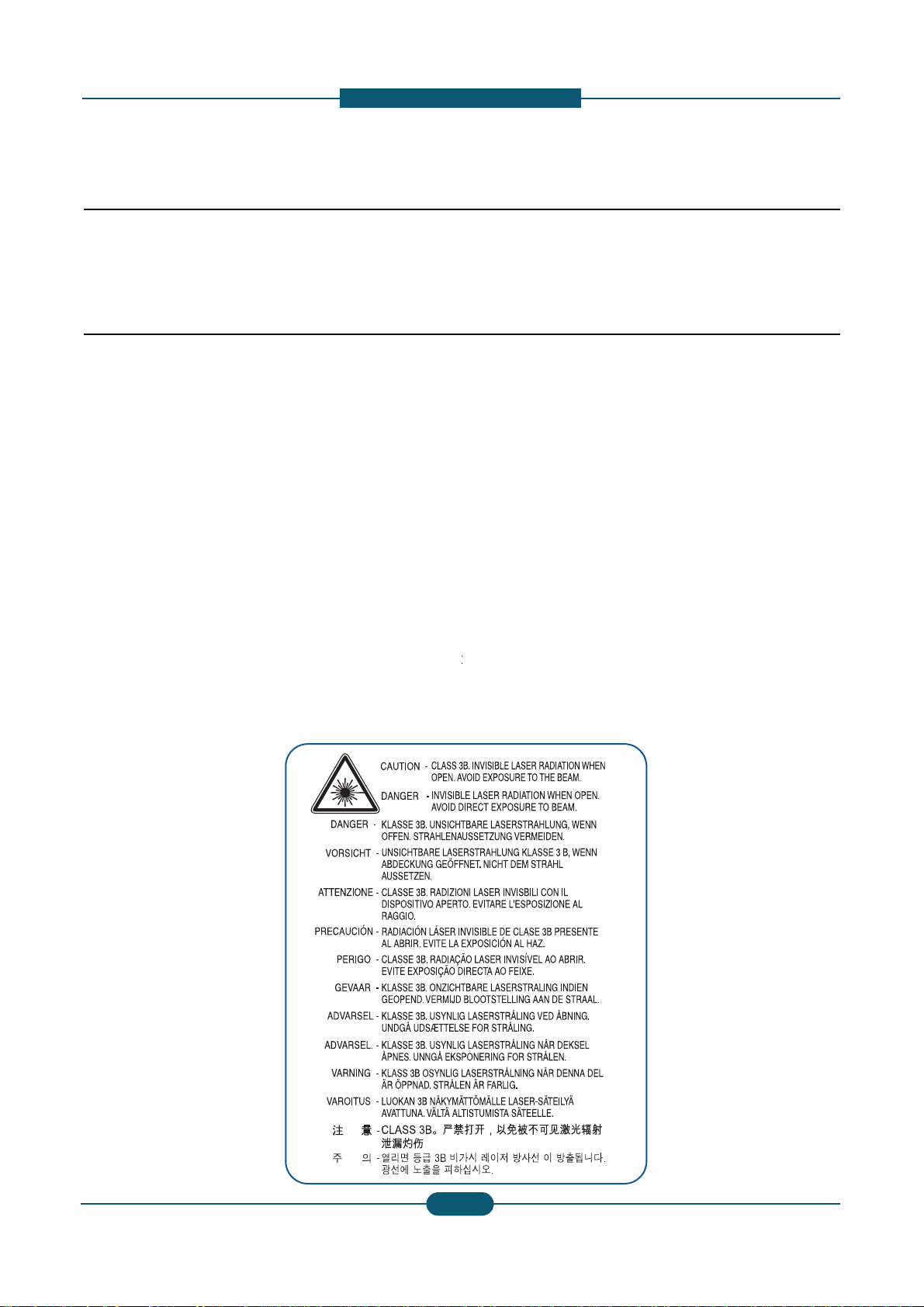
(3) Laser Safety Statement
The Printer is certified in the U.S. to conform to th
e
Subchapter J for Class 1(1) laser products, and el
s
f
orm
i
ng
t
o
th
e requ
i
remen
t
s o
f
IEC
825
.
Cl
ass
I
l
as
laser system and printer are designed so there is n
Class I level during normal operation, user mainte
n
Warning >> Never operate or service the printer with
t
assembly. The reflected beam, although invisible, can
When using this product, these basic safety pre-cauti
o
electric shock, and personal injury.
Service Manual
1
-
utions
for s afety
o
the equipment please read the precautions listed
them closely.
ce technician.
ngerous. This printer should only be serviced by a
er. Do not make any unauthorized changes or
inter to malfunction and create an electric shock or
requirements of DHHS 21 CFR, chap ter 1
ewhere, it is certified as a Class I laser product con-
er pro
d
uc
t
s are no
t
cons
id
ere
d
t
o
b
e
h
azar
d
ous.
Th
e
ever any human access to laser radiation above a
ance, or prescribed service condition.
he protective cover removed from Laser Scanner
damage your eyes.
ns should always be followed to reduce risk of fire,
SAMSUNG ELECTRONICS
1

1. Prec
a
1.2 Caution for safety
1.2.1 Toxic material
This product contains toxic materials that could cause
i
(1) If the LCD control panel is damaged it is possible f
o
with the skin should be avoided. Wash any splash
e
doctor. If the liquid gets into the mouth or is swallo
w
(2) Please keep Drum cartridge and Toner cartridge a
w
Drum cartridge and Toner Cartridge may be harmf
u
1.2.2 Electric shock and fire safety
p
Failure to follow the following instructions could cause
e
(1) Use only the correct voltage, failure to do so could
d
electric shock.
(
2
)
Use onl
y
the
p
ower cable su
pp
lied with the
p
rinter.
() y p pp p
cable to overheat and potentially cause a fire.
(3) Do not overload the power socket, this could lead t
o
lead to a fire.
(4) Do not allow water or other liquids to spill into the p
paper clips, pins or other foreign objects to fall into
to an electric shock or fire hazard.
(
5
)
Never touch the
p
lu
g
s on either end of the
p
ower c
a
() p g p
When servicing the printer remove the power plug
f
(6) Use caution when inserting or removing the power
c
firmly and pull. The power connector must be inser
t
overheating possibly leading to a fire.
(7) Take care of the power cable. Do not allow it to be
c
damaged. Do not place objects on top of the powe
r
overheat and cause a fire. Exposed cables could c
a
cable
immediately
,
do
not
reuse
or
repair
the
dama
the power cable, weakening the cover or exposing
(8) Ensure that the power sockets and plugs are not cr
a
should be repaired immediately. Take care not to c
the machine.
(9) Use caution during thunder or lightning storms. Sa
m
from the power source when such weather conditi
o
p
ower cord if it is still connected to the wall socket
i
p
(10) Avoid damp or dusty areas, install the printer in a
c
machine near a humidifier or in front of an air con
d
can lead to overheating and cause a fire or cause
(11) Do not position the printer in direct sunlight. This
w
possibly leading to the printer failing to work prop
e
(12) Do not insert any metal objects into the machine t
h
could make contact with a high voltage conductor
Service Manual
1
-
utions
llness if ingested.
r the liquid inside to leak. This liquid is toxic. Contac
t
s from eyes or skin immediately and contact your
ed see a doctor immediately.
ay from children. The toner powder contained in the
l and if swallowed you should contact a doctor.
recautions
lectric shock or potentially cause a fire.
amage the printer and potentially cause a fire or
Use of an incorrectl
y
s
p
ecified cable could cause the
yp
overheating of the cables inside the wall and could
rinter, this can cause electric shock. Do not allow
the printer these could cause a short circuit leading
ble with wet hands, this can cause electric shock.
rom the wall socket.
onnector. When removing the power connector, grip it
ed completely, otherwise a poor contact could cause
ome twisted, bent sharply around corners or wise
cable. If the power cable is damaged it could
use an electric shock. Replace the damaged power
cable
.
Some
chemicals
can
attack
the
coating
on
cables causing fire and shock risks.
cked or broken in any way. Any such defects
ut or damage the power cable or plugs when moving
sung recommends that this machine be disconnected
ns are expected. Do not touch the machine or the
n these weather conditions.
lean well ventilated location. Do not position the
itioner. Moisture and dust built up inside the machine
parts to rust.
ill cause the temperature inside the printer to rise
rly and in extreme conditions could lead to a fire.
rough the ventilator fan or other part of the casing, it
inside the machine and cause an electric shock.
SAMSUNG ELECTRONICS
2

1. Prec
a
1.2.3 Handling Precautions
The following instructions are for your own personal s
a
product.
(1)
Ensure
the
printer
is
installed
on
a
level
surface
,
ca
cause the printer to tip or fall.
(2) The printer contains many rollers, gears and fans.
fingers, hair or clothing in any of these rotating de
v
(3) Do not place any small metal objects, containers
o
which if spilled could get into the machine and ca
u
(4) Do not install the machine in areas with high dust
o
a humidifier or heater. Dama
g
e could be caused t
o
1.2.4 Assembly / Disassembly Preca
u
g
(5) Do not place candles, burning cigarettes, etc on th
(6) When reinstalling the imaging unit or ITB unit at p
o
Replace parts carefully and always use Samsung par
t
cable routing before dismantling any part of the machi
Please carry out the following procedures before dism
(1) Check the contents of the machine memory and m
if the main board or network card is replaced.
(2) Ensure that power is disconnected before servicin
g
(3)
Disconnect
printer
interface
cables
and
power
cabl
(4) Only use approved spare parts. Ensure that part n
u
temperature rating are correct.
(5) When removing or re-fitting any parts do not use e
x
plastic.
(6) Take care not to drop any small parts into the mac
(7) Handling of the OPC Drum
-
The
OPC
Drum
can
be
irreparably
damaged
if
it
e
Take care not to expose the OPC Drum either to
d
room lighting. Exposure for as little as 5 minutes
c
properties and will result in print quality degradati
o
Remove the OPC Drum and store it in a black ba
g
working with the Covers (especially the top cover
)
damage the OPC Drum.
- Take care not to scratch the green surface of OP
C
If the green surface of the Drum Cartridge is scra
t
compromised.
Service Manual
1
-
1
-
utions
fety, to avoid injury and so as not to damage the
of
supporting
its
weight
.
Failure
to
do
so
could
Take great care to ensure that you do not catch your
ices.
f water, chemicals or other liquids close to the printer
se damage, shock or fire hazard.
r moisture levels, beside on open window or close to
the
p
rinter in such areas.
tions
p
e printer, These could cause a fire.
wer off, perform the OPC-ACR surely.
s. Take care to note the exact location of parts and
ne. Ensure all parts and cables are replaced correctly.
antling the printer or replacing any parts.
ake a note of any user settings. These will be erased
or replacing any electrical parts.
.
mber, product name, voltage, current and
cessive force, especially when fitting screws into
hine.
to
light
.
irect sunlight or to fluorescent or incandescent
an damage the surface of the photoconductive
n. Take extra care when servicing the printer.
or other lightproof container. Take care when
open as light is admitted to the OPC area and can
Drum Unit.
ched or touched the print quality will be
SAMSUNG ELECTRONICS
3
3

1. Prec
a
1.2.5 Disregarding this warning may
(1) Be careful with high temperature compone nts.
The fuser unit works at a high temperature. Use ca
u
cool down before disassembly.
(2) Do not put fingers or hair into the rotating parts.
When operating a printer, keep your hands and hai
r
motor, fan, etc.).
(3) When moving the printer :
- When transporting/installing the equipment, employ f
o
- Be sure not to hold the movable parts or units (e.g. th
equipment.
- Be sure to use a dedicated outlet with 110V/220V po
w
- The equipment must be grounded for safety.
- Select a suitable place for installation. Avoid excessi
v
sunlight.
- Provide proper ventilation since the equipment emits
- The e
q
ui
p
ment must be installed near the socket outl
qp
-Be sure to fix and plug in the power cable securely aft
e
-If you are moving the machine a short distance, you s
h
(e.g : same building through elevator)
-If you are moving the machine a long distance, you s
h
& staple unit, tape and disassemble all trays. (e.g :
m
Service Manual
1
-
utions
cause bodily injury
tion when working on the printer. Wait for the fuser to
away form the rotating parts (Paper feeding entrance,
ur people and be sure to hold the lifting handles.
e control panel, DADF) when transporting the
er input.
e heat, high humidity, dust, vibration and direct
a slight amount of ozone.
et and must be accessible.
e
r the installation so that no one trips over it.
ould separate the finisher.
ould remove toner & imaging unit, lock scan carrier
oved by truck or so)
SAMSUNG ELECTRONICS
4

1. Prec
a
1.3 ESD Precautions
Certain semiconductor devices can be easily damage
d
commonly called “Electrostatically Sensitive (ES) Dev
integrated
circuits
,
some
field
effect
transistors
,
and
se
The techniques outlined below should be followed to
h
caused by static electricity.
Caution >>Be sure no power is applied to the chassis
1. Immediately before handling a semiconductor com
p
off any electrostatic charge on your body by touchi
n
commercially available wrist strap device, which sh
o
prior to applying power to the unit under test.
2. After removing an electrical assembly equipped wit
h
such as aluminum or copper foil, or conductive foa
m
vicinity of the assembly.
3. Use only a grounded tip soldering iron to solder or
d
“
”
4
.
Use
only
an
anti
-
static
solder
removal
device
.
Som
static” can generate electrical charges sufficient to
5. Do not use Freon-propelled chemicals. When spra
y
damage ESDs.
6. Do not remove a replacement ESD from its protecti
v
Most replacement ESDs are packaged with all lead
s
or a comparable conductive material.
7. Immediately before removing the protective shortin
g
touch the protective material to the chassis or circui
8. Maintain continuous electrical contact between the
E
until completely plugged or soldered into the circuit.
9. Minimize bodily motions when handling unpackage
d
the brushing together of clothing fabric and lifting o
n
electricity
sufficient
to
damage
an
ESD
.
Service Manual
1
-
utions
by static electricity. Such components are
ices” or ESDs. Examples of typical ESDs are:
“
”
chip
components
.
elp reduce the incidence of component damag e
or circuit, and observe all other safety precautions.
onent or semiconductor-equipped assembly, drain
g a known earth ground. Alternatively, employ a
uld be removed
f
or your personal sa
f
ety reasons
ESDs, place the assembly on a conductive surface ,
, to prevent electrostatic charge buildup in the
esolder ESDs.
“
solder
removal
devices
not
classified
as
anti
-
damage ESDs.
ed, these can generate electrical charges sufficient to
v
e packaging until immediately before installing it.
s
shorted together by conductive foam, aluminum foil,
material from the leads of a replacement ESD,
t assembly into which the device will be installed.
SD and the assembly into which it will be installed,
replacement ESDs. Normal motions, such as
e’s foot from a carpeted floor, can generate static
SAMSUNG ELECTRONICS
5

2. Product
d
2.1 Specifications
2. Product description
2.1.1 Product Overview
CLX-9252/9352 series
Service Manual
2
-
escription
Print
and
Copy
speed
(Color/Mono)
CLX-9252NA : Up to 25 ppmin A4
CLX-9352NA : Up to 35 ppmin A4
Scan Speed
60 ipm @ 300 dpi
Processor
A9
Dual
Core
1GHz
HDD : 320 GB
1.5GB memory
Options
HCF, DCF, Standard Finisher(1K)
B
oo
kl
e
t
Fi
n
i
s
h
er
(3K)
,
F
ax e
t
c.
• 8.9” Full color touch LCD
• XOA(eXtensible Open Architecture) support
SAMSUNG ELECTRONICS
1
2. Product
d
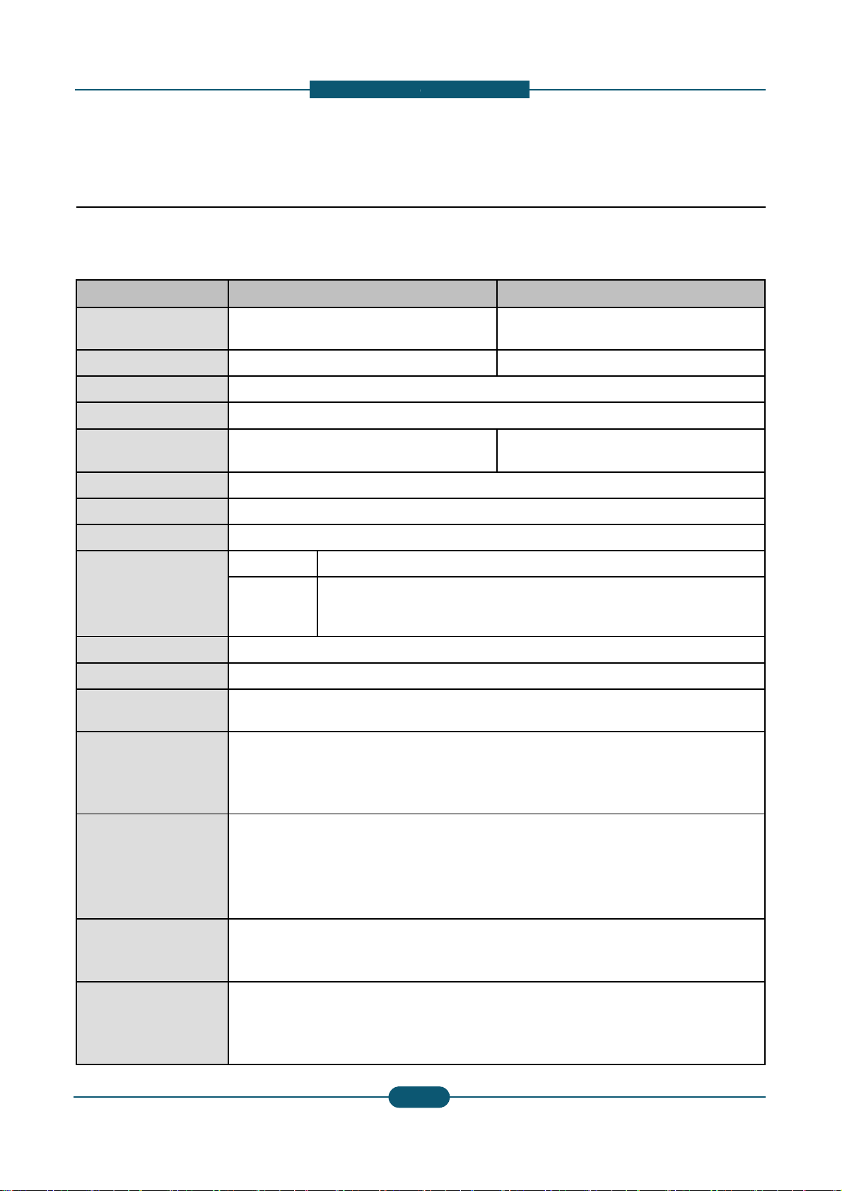
2.1.2 Specifications
General Specifications
Item CLX-9252NA
Printing Speed (A4)
(Color / Mono)
25 ppm/ 25 ppm
FCOT (Color / Mono) < 10.6 sec / < 9.0 sec
Warm-up Time < 45 sec from Power Save
Duplex Printing Speed Same as rated engine speed
Scanning Speed (A4)
60 ipm @ 300 dpi
40 ipm @ 600 dpi
Memory 1.5GB
HDD 320 GB
CPU
A9 Dual Core 1GHz
Resolution
Optical • 600 x 600 dpi
Enhanced
• Draft 600 x 60
0
• Default 600 x 6
• Up to 600 x 60
0
Gradation 256
Size (W x D x H ) 675.5 x 722 x 1153 mm (26.6 x
Weight
96.71 Kg (213.21 lbs.) (without
c
110 Kg (312 lbs.) (including con
s
Noise (dB)
• Low Power mode : 34 dB(A)
• Ready mode : 43 dB(A)
• Printing mode : 54 dB(A)
• Copying mode : 57 dB(A)
Power consumption
• Average operating mode : Les
s
• Ready mode : Less than 250
W
• Low power mode : Less than 5
0
• Power save mode : Less than
1
• Power off mode : Less than 0
W
Power requirement
AC 110-127 V , 50/60 Hz or: A
C
Note - See the Rating label on t
h
type of current.
Power output rating for
heating wire in
DCF/HCF
AC 110-127 V , 50/60 Hz or AC
2
Note - See the Rating label on t
h
of current.
The voltage rating of heating wir
e
Service Manual
2
-
escription
CLX-9352NA
35 ppm/ 35 ppm
< 8.5 sec / < 7.5 sec
60 ipm @ 300 dpi
40 ipm @ 600 dpi
x 1bit
00 x 2 bit
x 4 bit
28.4 x 45.4 inches)
onsumables and options )
umables without options)
than 1,100 W
W
1 W
220-240 V , 50/60 Hz
e machine for the correct voltage, frequency (hertz) and
20-240 V , 50/60 Hz
e machine for correct voltage, frequency (hertz) and type
is the same as the machine’s voltage rating.
SAMSUNG ELECTRONICS
2
2. Product
d
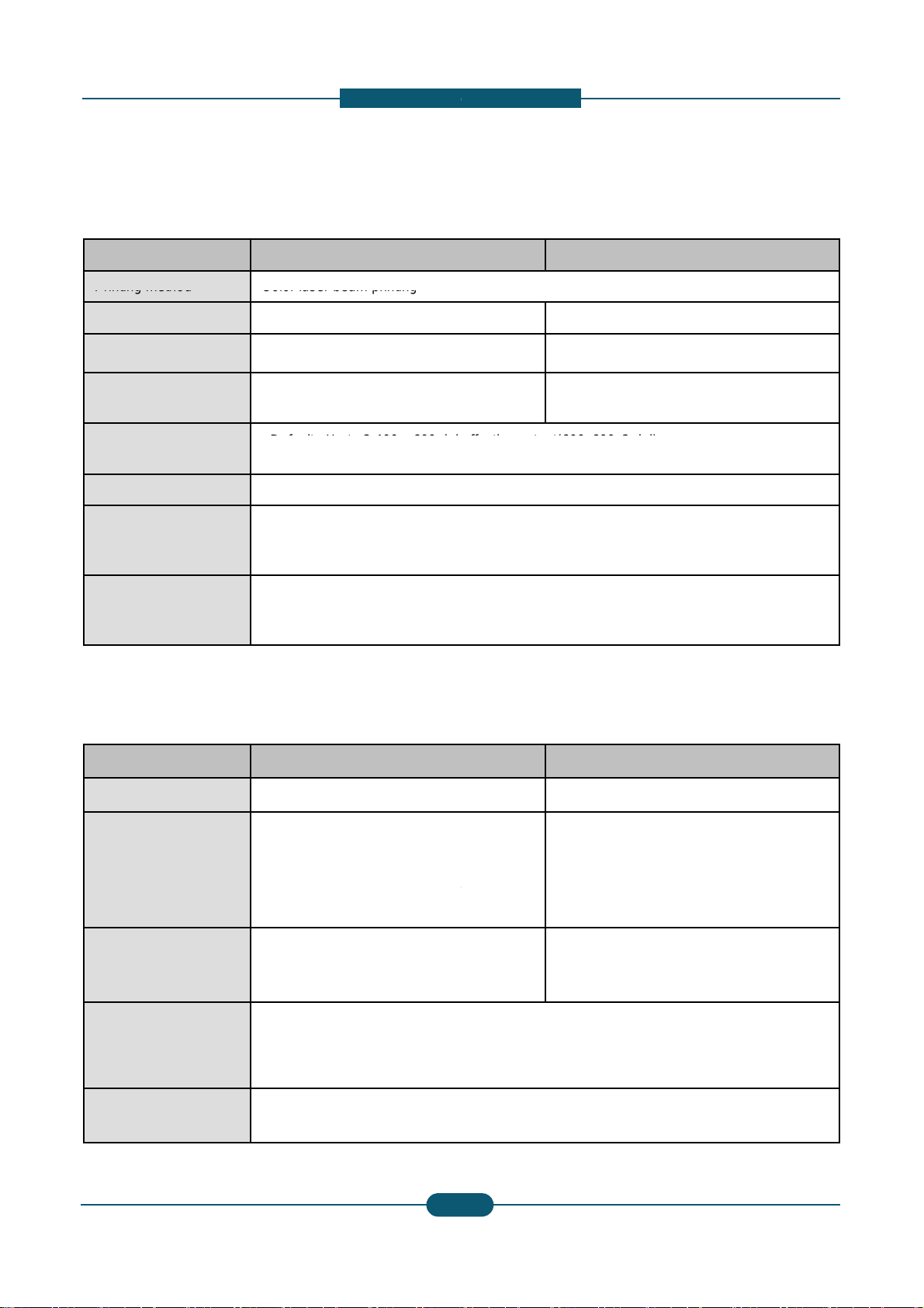
Item CLX-9252NA
Printer Specifications
Printing
method
Color
laser
beam
printing
Printing speed Up to 25 ppm (A4), 25 ppm (Lett
Duplex printing speed Up to 25 ipm (A4), 25 ipm (Lette
r
First print out time
(Color / Mono)
< 12.2 sec / < 10.6 sec
Print resolution
•
D
e
f
au
lt
:
U
p
t
o
2
,
400
x
600
d
p
i
• Max : Up to 9,600 x 600 dpi eff
e
Printer language PCL5Ce, PCL6C, PostScript 3,
P
OS compatibility
• Windows: 2000 ,XP,2003 ,Vist
a
• Various Linux OS
• Macintosh: Mac OS X 10.5~10
.
Interface
• High speed USB 2.0
• Ethernet 10/100/1000 Base T
X
• FDI (optional)
Copier specifications
Item CLX-9252NA
Copy Speed Up to 25 cpm (A4), 25 cpm (Lett
e
Simplex to Duplex (1-2)
: Up to 25 ipm in A4 (25 ipm in L
e
Duplex
copy
speed
Duplex
to
Duplex
(2
-
2)
: Up to 8 ipm in A4 (8 ipm in Lett
e
@ normal mode
First copy out time
• Black & white: 9.0 seconds
(from ready)
• Color: 10.6 seconds (from read
Copy resolution • Platen : 600 x 600 dpi
• Document feeder: Up to 600 x
6
Zoom range
• Platen : 25% to 400%
• Document feeder: 25% to 400
%
Service Manual
2
-
escription
CLX-9352NA
er) Up to 35 ppm (A4), 35 ppm (Letter)
) Up to 35 ipm (A4), 35 ipm (Letter)
< 10.5 sec / < 9.5sec
e
ff
ec
ti
ve ou
t
pu
t(600
x
600
x
2
d
p
i)
ctive output(600x600x2 dpi)
DF 1.5+, TIFF, PJL, XPS
,2008 ,Win7
6
(embedded type)
CLX-9352NA
r) Up to 35 cpm (A4), 35 cpm (Letter)
tter)
Simplex to Duplex (1-2)
: Up to 35 ipm in A4 (35 ipm in Letter)
r)
Duplex
to
Duplex
(2
-
2)
: Up to 22 ipm in A4 (22 ipm in Letter) @
normal mode
y)
• Black & white: 7.5 seconds
(from ready)
• Color: 8.5 seconds (from ready)
00 dpi
SAMSUNG ELECTRONICS
3
2. Product
d
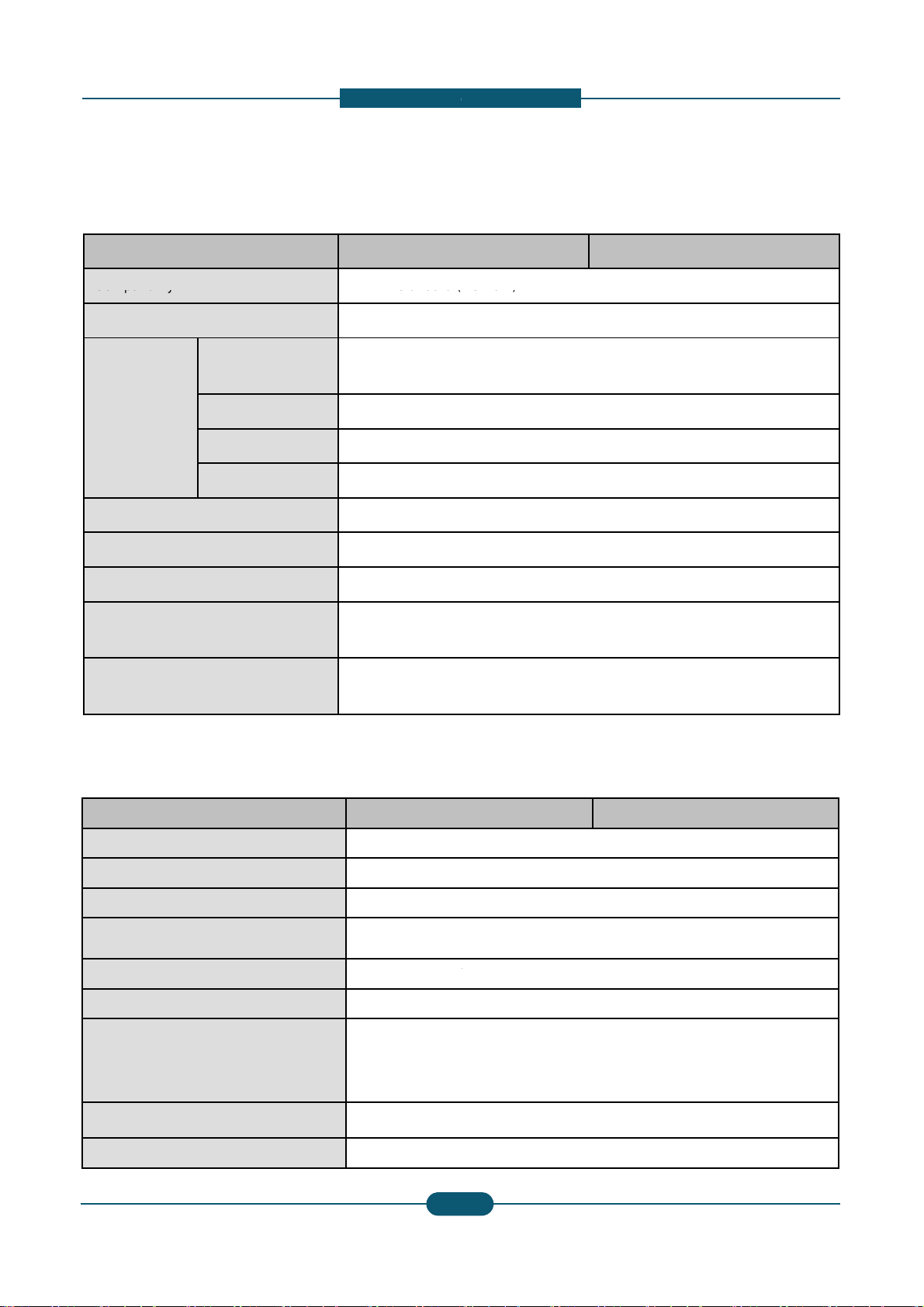
Item CLX-9252NA
Scanner specifications
Compatibility
TWAIN
standard
(
Scanning method Color CCD
Resolution
TWAIN standard
Up to 600 x 600 d
p
(Up to 4,800 x 4,8
0
Scan to USB 100, 200, 300, 40
0
Scan to Email 100, 200, 300, 40
0
Scan to Server 100, 200, 300, 40
0
Network Scan File format PDF, TIFF, JPEG
Effective scanning length Max. 432 mm (17
Eff
ec
ti
ve scann
i
ng w
idth
M
ax.
297
mm
(11
.
Color bit depth
Internal: 30 bit
External: 24 bit
Mono bit depth
1 bit for lineart &
h
8 bit for gray scal
e
Item CLX-9252NA
Compatibility Super G3
Fax Specifications
Applicable
line
P
u
blic
S
w
itched
T
Data coding MH/MR/MMR/JB
Modem speed 33.6kbps
Transmission speed Up to 3 seconds
/
Maximum document length 356 mm (14 inch
Resolution
• Standard : 203
x
• Fine : 203 x 19
6
• Super Fine : 30
• Ultra Fine : 600
Memory HDD Backup
Auto dialer up to 500 numbe
Service Manual
2
-
escription
CLX-9352NA
Network)
i
0 dpi by software enhancement)
, 600 dpi
, 600 dpi
, 600 dpi
inches)
7
i
nc
h
es
)
alftone
CLX-9352NA
Net
w
ork
(PSTN)
or
behind
PABX
IG/JPEG
page
es)
x
98 dpi
dpi
0 x 300 dpi
x 600 dpi
rs
SAMSUNG ELECTRONICS
4

2. Product
d
Item CLX-9252NA
• Standard : 1,040 (Cassette
Paper Specifications
Input
Paper
Capacity
•
M
ax
i
mum :
1
,
040
(C
asse
tte
Output Paper Capacity
• Standard : 500 (Center Out
p
• Maximum : 3,250 (Booklet
F
Paper Size
• Cassette :
148 x 210 mm
•MP Tray :
98 x 148 mm(3
.
•
High
Capacity
Feeder
:
A4
/
Paper Type
• Cassette :
Plain Pa
p
er, Th
Label, CardStoc
k
• MP Tray :
Printer Default,
Color Paper, C
a
Letterhead, Re
c
• High Capacity Feeder :
Pla
i
Re
c
Paper Weight
• Cassette : 60 ~ 216 gsm
(1
• MP Tray : 60 ~ 253 gsm
(1
6
• High Capacity Feeder : 60
~
Original Capacity for DADF 100 sheets
Original Size for DADF
• Full supported Size : 140 X
• Auto-detected Size : A3, B
4
Original Weight for DADF
• Simplex : 42 ~ 163 gsm (3
0
• Duplex : 50 ~ 128 gsm (30l
b
Service Manual
2
-
escription
CLX-9352NA
1 & 2) + 100 (MP Tray)
1
&
2)
+
2
,
000
(Hi
g
h
C
apac
it
y
F
ee
d
e
r
)
+
100
(MP
T
ray
)
ut Tra
y
)
inisher)
(5.83”x 8.27”) ~ 305 x 457 mm (12”x 18”)
8”x 5.8”) ~ 320 x 1200 mm (12.6”47”)
Letter
in Pa
p
er, Bond, Punched, Pre-Printed, Recycled,
, Letterhead, Thick, Cotton, Colored, Archive, Glossy
Plain Pa
p
er, Thick Pa
p
er, Thin Pa
p
er, Bond Pa
p
er,
rdStock, Labels, Transparency, Envelope, Preprinted,
cled Pa
p
er, Cotton, Archive, Gloss
y
n Pa
p
er, Thin Pa
p
er, Bond, Punched, Pre-Printed,
cled, Letterhead,Thick paper
6lb Bond ~ 90lb Index)
lb Bond ~ 90lb Cover)
120 gsm
(16lb Bond ~ 90lb Index)
140mm ~ 297 x 432mm (5.5" x 5.5" ~ A3/Ledger)
, B4 SEF, A4, A4 SEF, B5, B5 SEF, A5, A5 SEF
lb Book ~ 90lb Index)
Book ~ 34lb Bond)
SAMSUNG ELECTRONICS
5
2. Product
d
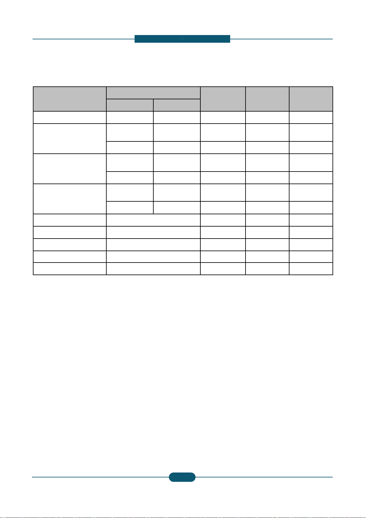
Product
Model name
N.A / KOR ELS
Consumables
Black Tone
r
CLT-K606S CLT-K60
Cyan Toner
CLT-C606S CLT-C60
CLT-C607S CLT-C60
Magenta Toner
CLT-M606S CLT-M6
0
CLT-M607S CLT-M6
0
Yellow Toner
CLT-Y606S CLT-Y60
CLT-Y607S CLT-Y60
Black Imaging Unit CLT-R607K
Cyan Imaging Unit CLT-R607C
Magenta Imaging Unit CLT-R607M
Yellow Imaging Unit CLT-R607Y
Waste Toner Container CLT-W606
*
D
ec
l
are
d
y
i
e
ld
va
l
ue
i
n accor
d
ance w
ith
6%
pa
tt
er
n
** Image counts are based on one color on each pag
Magenta, Cyan, Black), the number of image is 4 im
a
Service Manual
2
-
escription
Life CLX-9252NA CLX-9352NA
62S 25K pages O O
62S 20K pages
X (Not
Available)
O
72S 15K pages O O
62S 20K pages
X (Not
Available)
O
72S 15K pages O O
62S 20K pages
X (Not
Available)
O
72S 15K pages O O
75K pages O O
75K pages O O
75K pages O O
75K pages O O
75K images O O
e. If you print a document in full color (Yellow,
ges.
SAMSUNG ELECTRONICS
6
2. Product
d
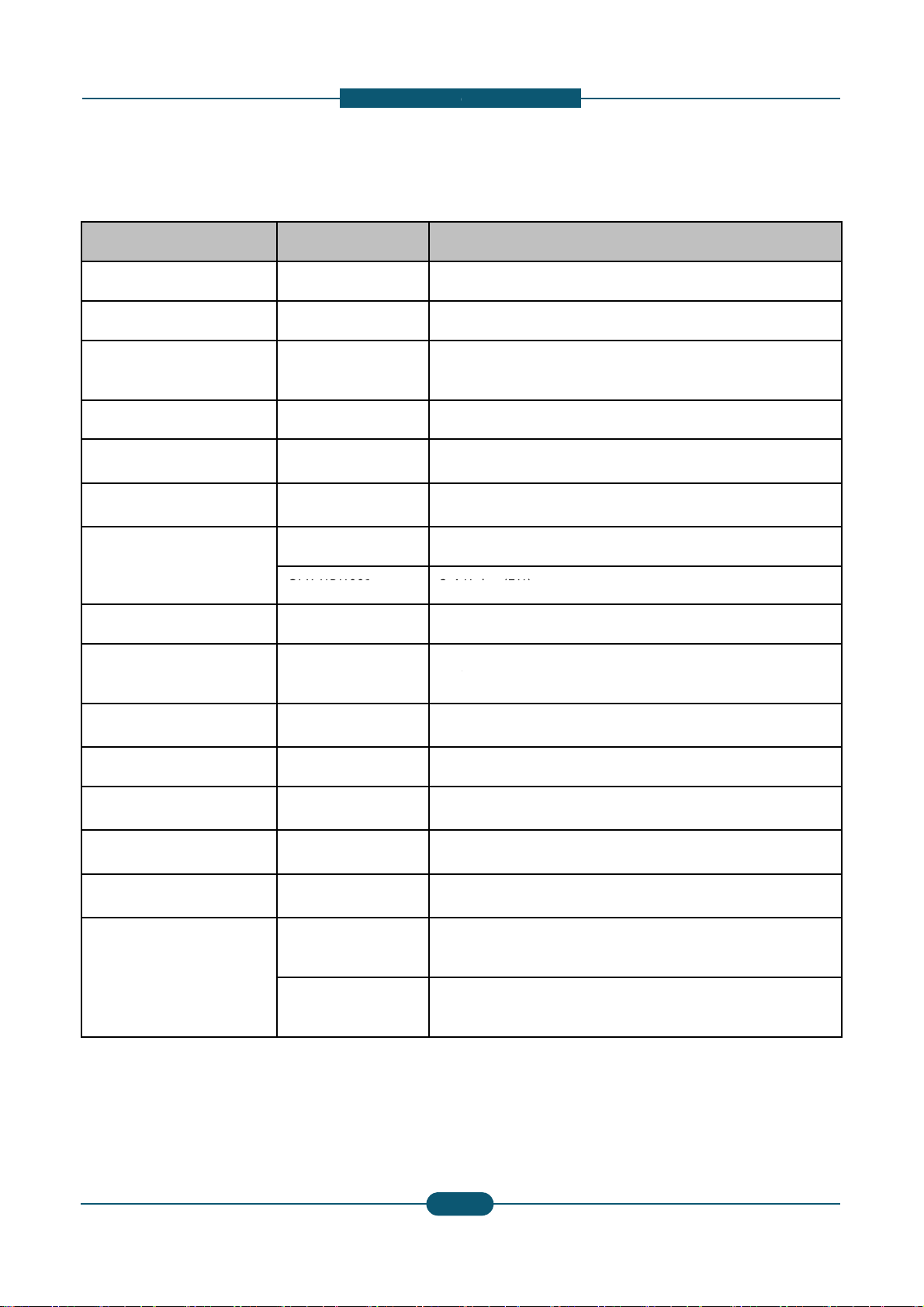
Option Unit Model name Re
m
Stand CLX-DSK10T
Option Unit
Dual Cassette Tray CLX-PFP000 52
0
HCF
(High Capacity Feeder)
CLX-HCF102 2,0
0
Bridge Unit CLX-BRG200
Standard Finisher CLX-FIN40S 1,2
5
Booklet Finisher CLX-FIN40L 3,2
5
Punch Kit
CLX-HPU000 2-3
CLX
-
HPU001
2
-
4
Working Table CLX-WKT000
Foreign Device Interface
(FDI) Kit
CLX-KIT10F Se
r
Fax
Kit
CLX
-
FAX160
G3
,
Fax Multiline Kit CLX-FAX260 G3
SmarThru Workflow Do
c
CounThru2 Co
u
Advanced PDF Kit Se
a
Heating wire for Cassette,
HCF, DCF
CLX-DHK11C
11
0
of
H
CLX-DHK12C
22
0
of
H
Service Manual
2
-
escription
ark
Sheet Tray x 2
0 Sheets (LTR, A4)
0 Stacking, Stapling (4 Pos)
0 Stacking, Stapling (4 Pos), Booklet
Holes (NA)
H
o
l
es
(EU)
ial Port
T
.
37/38
,
PC
Fax
SW
,
Fax
Manual
Softcopy
ument Distribution Solution
nter and Cost Management Solution
rchable PDF, Barcode, etc.
V, 10W (equipped by service person at field, voltage rating
eating Wire is the same as the machine’s voltage rating)
V, 10W (equipped by service person at field, voltage rating
’
Wire
is
the
same
as
the
machine s
voltage
rating)
SAMSUNG ELECTRONICS
7
2. Product
d
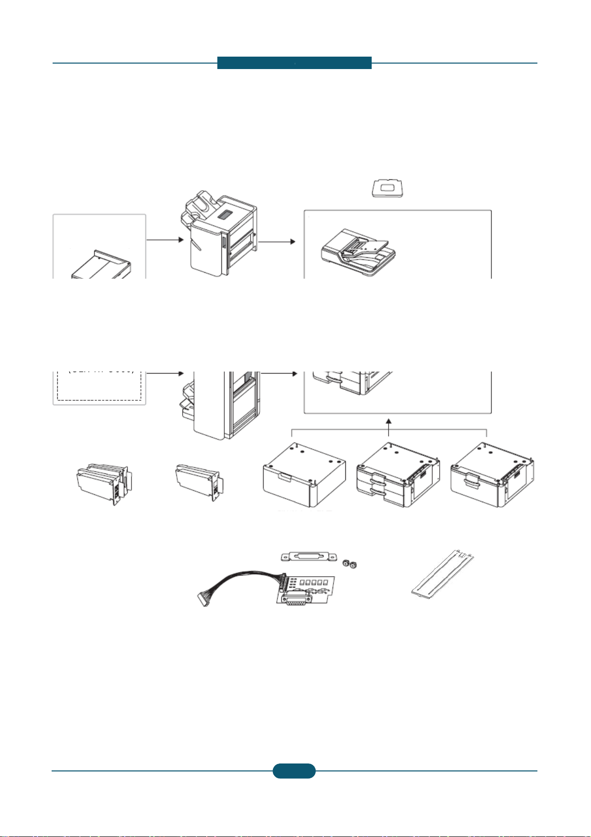
Option unit configuration
1,250-sheet standard finisher
-
(CLX
FIN40S)
Bridge kit
(CLX-BRG200)
3,250-sheet booklet finisher
(CLX-FIN40L)
2/3 hole Punch kit
-
(CLX
HPU000)
2/4 hole Punch kit
(CLX-HPU001)
St
(CLX-
D
Fax kit
(CLX-FAX160)
Fax multi-line kit
(CLX-FAX260)
F
D
(CL
X
Service Manual
2
-
escription
Working Table
(CLX-WKT000)
Duplex Automatic Document Feeder
Main unit
and
SK10T)
Optional tray
(CLX-PFP000)
High capacity feeder
(CLX-HCF102)
I kit
-KIT10F)
Cassette Heating cable
(CLX-DHK11C/12C)
SAMSUNG ELECTRONICS
8

2. Product
d
Item Model
CLX-9250/9350
(Cosmos Color)
C
(
C
Cosmos / Cosmos-R Option Unit Com
p
Stand CLX-DSK10T O
DCF CLX-PFP000 O
HCF CLX-HCF102 O
Bridge Unit CLX-BRG200 O
1K Finisher CLX-FIN40S O
3K Finisher CLX-FIN40L O
Punch Kit
CLX-HPU000 O
CLX-HPU001 O
Staples Cartridge SCX-STP000 O
Working Table CLX-WKT000 O
Job
seperator
SCX
-
JST000
X
FDI Kit CLX-KIT10F O
Fax Kit
CLX-FAX150 O
CLX-FAX160 X
Fax Multi Kit
CLX-FAX250 O
CLX-FAX260 X
Heating Wire
for HCF, DCF
CLX-DHK11C O
CLX-DHK12C O
Heating Wire
for Scan
CLX-DHK11S O
CLX-DHK12S O
Service Manual
2
-
escription
LX-9252/9352
osmos-R Color)
SCX-8030/8040
(Cosmos Mono)
SCX-8230/8240
(Cosmos-R Mono)
atibilit
y
OOO
OOO
OOO
OOO
OOO
OOO
OOO
OOO
OOO
OOO
X
O
O
OOO
XOX
OXO
XOX
OXO
OOO
OOO
XOX
XOX
SAMSUNG ELECTRONICS
9
2. Product
d
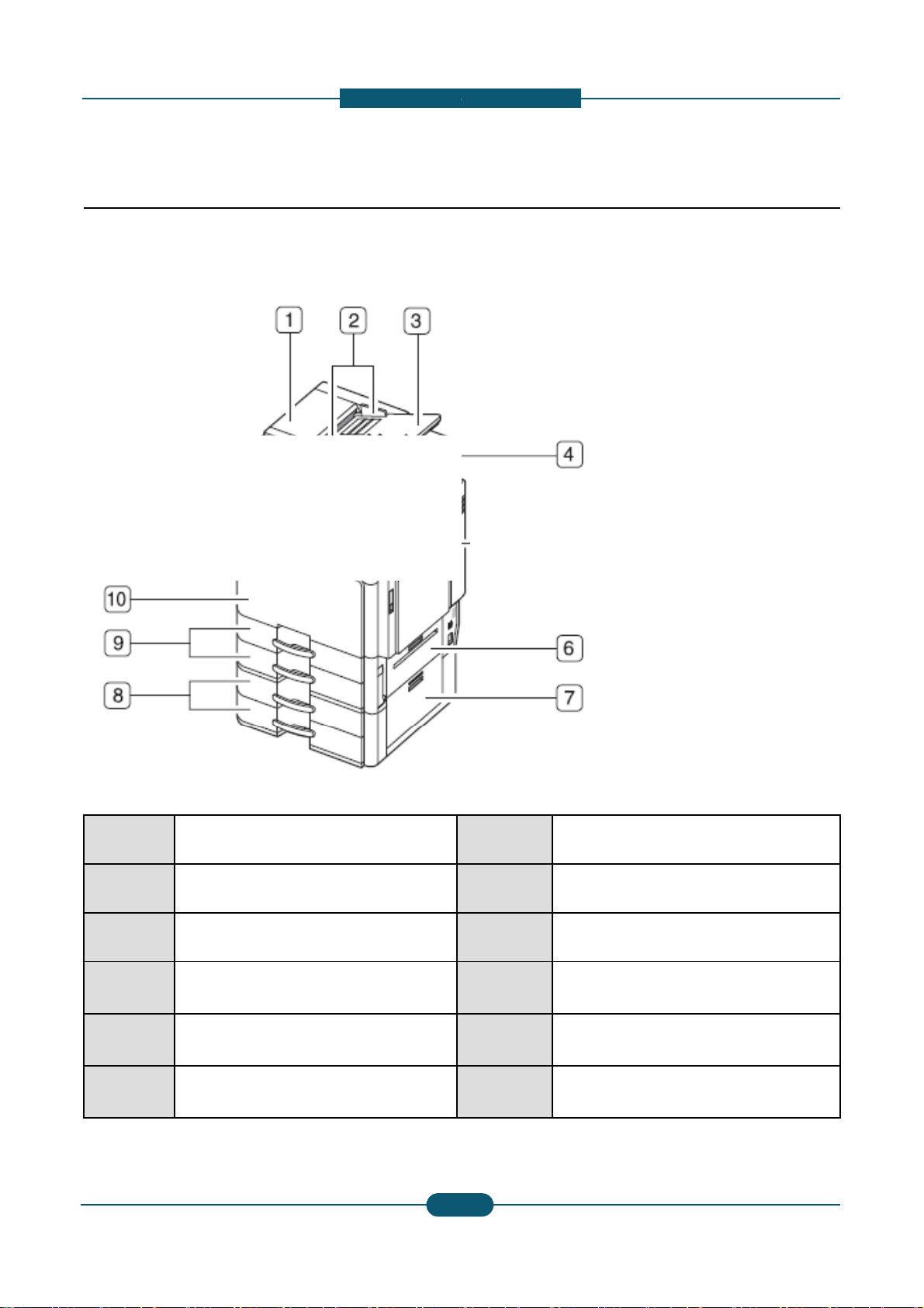
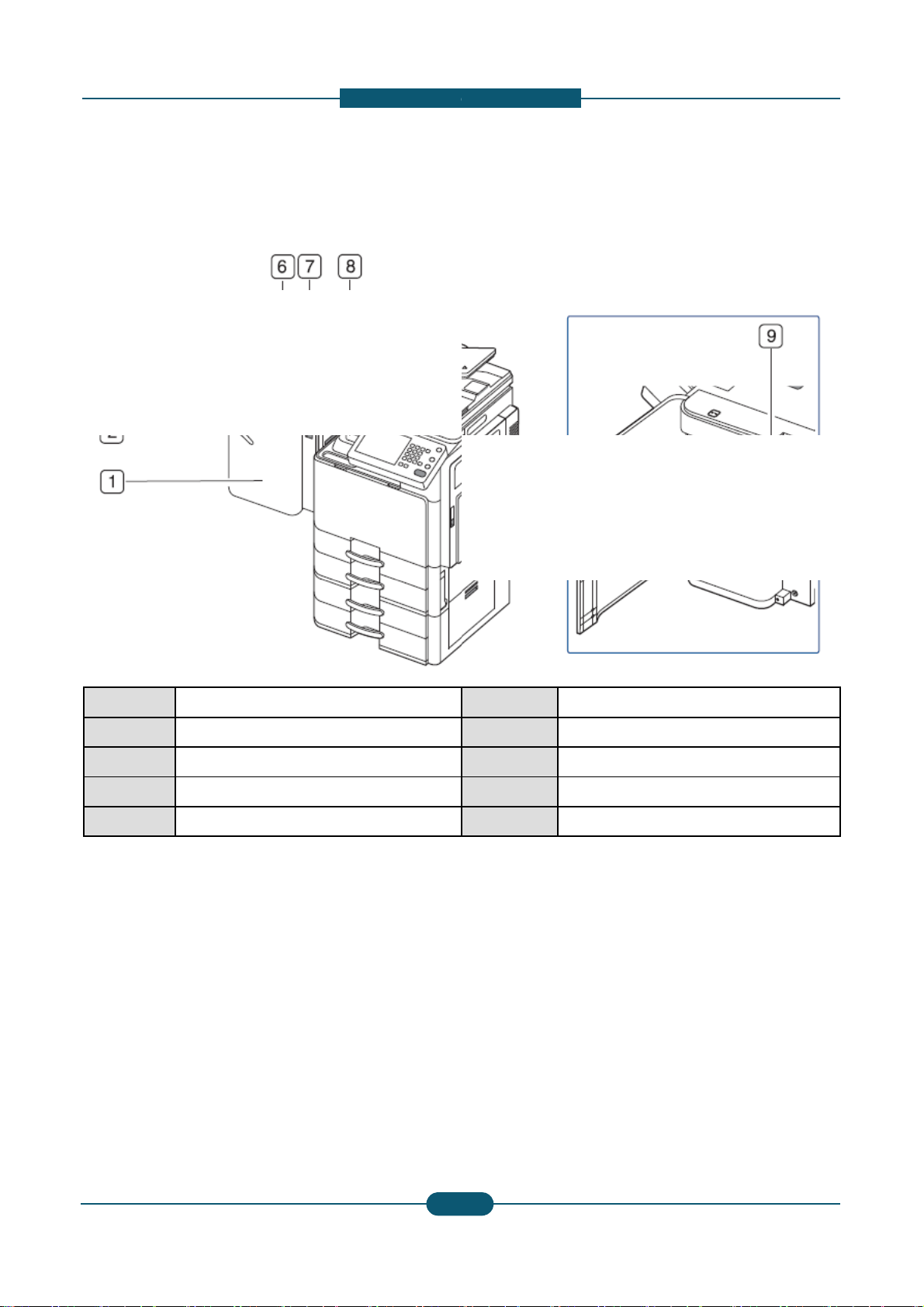
2.2 System configuration
Front view 1
1
Duplex automatic document feeder
cover
2
Duplex automatic document feeder
width guides
3
Duplex automatic document feeder
input tray
4
Duplex automatic document feeder
output tray
6 Standard tray right bottom door
7
Optional dual cassette feeder right
bottom door
Service Manual
2-
1
escription
8
Optional dual cassette feeder (tray 3,
tray 4)
9 Standard tray (tray 1, tray 2)
10 Front door
11 Front door hand le
12 Contro l panel
13 Cente r tray
SAMSUNG ELECTRONICS
0
2. Product
d
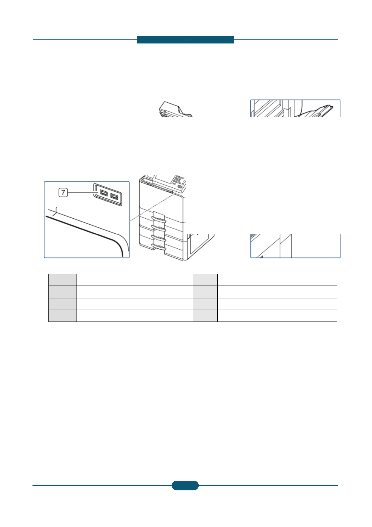
Front view 2
1 Scanner glass
2
White
sheet
3 Multi-purpose tray
4 Multi-purpose tray paper width guide
Service Manual
2-
1
escription
5 Power-switch
6
Power
receptacle
7 USB port (2 EA)
SAMSUNG ELECTRONICS
1

2. Product
d
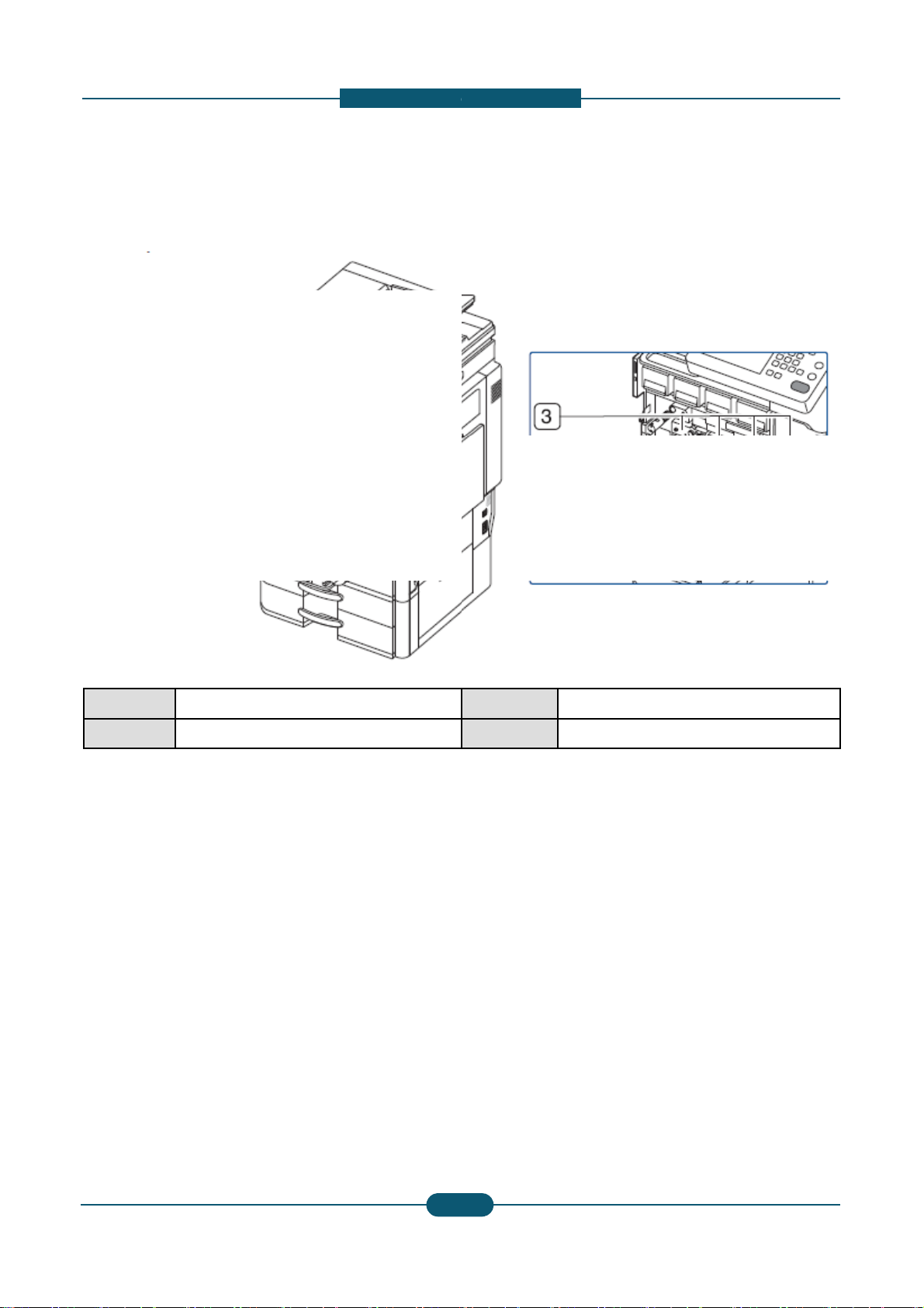
Rear view
1 Optional dual cassette feeder cable
2 DADF cable
3 Scanner locking screw
Service Manual
2-
1
escription
4
6
5
4 USB host port
5 Finisher connector
6 Network port
SAMSUNG ELECTRONICS
2
2. Product
d
Inner view
1 Waste toner container
2 Toner cartridge
Service Manual
2-
1
escription
3 Imaging units
4 Inner cover
SAMSUNG ELECTRONICS
3
2. Product
d
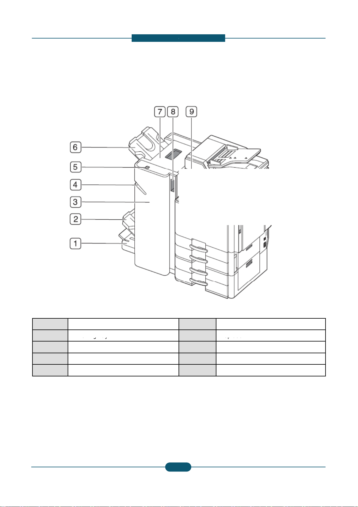
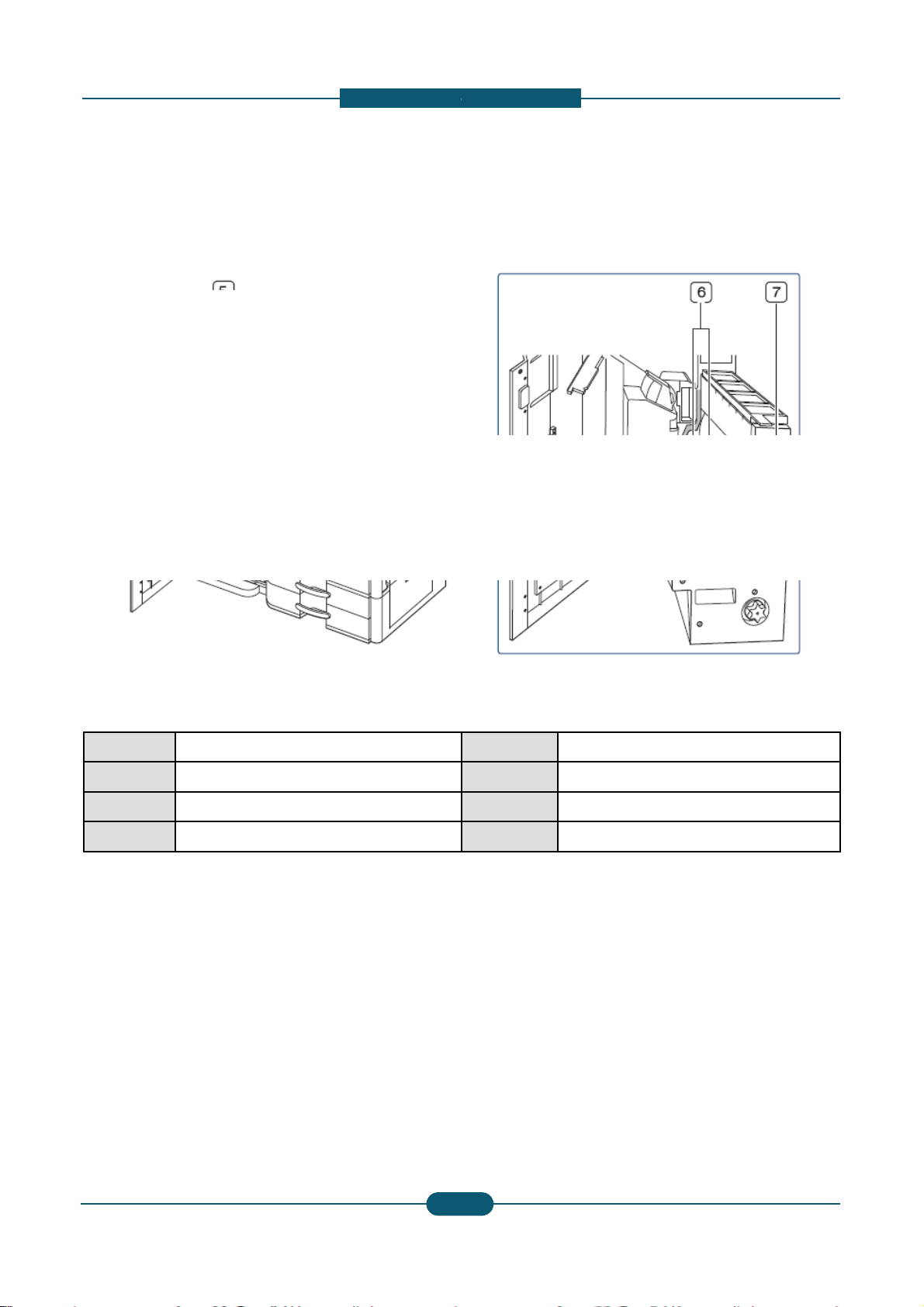
V
iew with standard finisher (option
1 Standard finisher front door
2 Manual stapler
3 Manual stapler button
4 Finishing tray
5 Top tray
Service Manual
2-
1
escription
al)
6 Top door
7 Standard finisher Front door handle
8 Bridge Unit
9 Staple
SAMSUNG ELECTRONICS
4
2. Product
d
View with booklet finisher1 (option
a
1 Booklet tray
2
Finishing
tray
3 Booklet finisher front door
4 Manual stapler
5 Manual stapler button
Service Manual
2-
1
escription
l)
6 Top tray
7
Top
door
8 Booklet finisher front door handle
9 Bridge Unit
SAMSUNG ELECTRONICS
5
2. Product
d
View with booklet finisher2 (option
a
1 Knife wheel
2 Booklet maker handle
3 Fold wheel
4 Booklet jam removal wheel
Service Manual
2-
1
escription
l)
5 Staple
6 Booklet Staple (2 EA)
7 Booklet maker cover
SAMSUNG ELECTRONICS
6
Loading...