


 Loading...
Color Laser Printer
CLP-36x series
CLP-36x / 36xW
(Ver 1.01)
SERVICEMANUAL
Color Laser Printer |
|
Contents |
1. Precautions
2. Product specification and description
3. Disassembly and Reassembly
4. Alignment and Troubleshooting
5. System Diagram
6. Reference Information
Refer to the service manual in the GSPN (see the rear cover) for more information.

Contents
Contents
1. Precautions ...................................................................................................................................... |
|
|
1 |
− |
1 |
|
1.1. |
Safety warning ........................................................................................................................ |
|
1 |
− |
1 |
|
1.2. |
Caution for safety .................................................................................................................... |
|
1 |
− |
2 |
|
|
1.2.1. |
Toxic material............................................................................................................. |
1 |
− |
2 |
|
|
1.2.2. Electric shock and fire safety precautions ......................................................................... |
1 |
− |
2 |
||
|
1.2.3. |
Handling precautions ................................................................................................... |
1 |
− |
3 |
|
|
1.2.4. Assembly and Disassembly precautions........................................................................... |
1 |
− |
3 |
||
|
1.2.5. Disregarding this warning may cause bodily injury ............................................................ |
1 |
− |
4 |
||
1.3. |
ESD precautions...................................................................................................................... |
|
1 |
− |
5 |
|
2. Product specification and description..................................................................................................... |
2 |
− |
1 |
|||
2.1. |
Product Specification................................................................................................................ |
2 |
− |
1 |
||
|
2.1.1. |
Product Overview........................................................................................................ |
2 |
− |
1 |
|
|
2.1.2. |
Specifications ............................................................................................................. |
2 |
− |
2 |
|
|
|
2.1.2.1. |
General Print Engine...................................................................................... |
2 |
− |
2 |
|
|
2.1.2.2. |
Controller and Software.................................................................................. |
2 |
− |
2 |
|
|
2.1.2.3. |
Paper Handling............................................................................................. |
2 |
− |
3 |
|
|
2.1.2.4. |
Reliability and Service ................................................................................... |
2 |
− |
4 |
|
|
2.1.2.5. |
Environment ................................................................................................ |
2 |
− |
4 |
|
|
2.1.2.6. |
Consumables................................................................................................ |
2 |
− |
5 |
|
|
2.1.2.7. |
Maintenance Parts ......................................................................................... |
2 |
− |
5 |
|
2.1.3. |
Model Comparison Table.............................................................................................. |
2 |
− |
6 |
|
2.2. |
System Overview..................................................................................................................... |
|
2 |
− |
7 |
|
|
2.2.1. |
Front View................................................................................................................. |
2 |
− |
7 |
|
|
2.2.2. |
Rear View |
.................................................................................................................. |
2 |
− |
8 |
|
2.2.3. |
Paper Path.................................................................................................................. |
2 |
− |
9 |
|
|
2.2.4. |
System Layout............................................................................................................ |
2 |
− 10 |
||
|
|
2.2.4.1. |
Feeding Section ............................................................................................ |
2 |
− 11 |
|
|
|
2.2.4.2. |
Transfer Roller ............................................................................................. |
2 |
− 12 |
|
|
|
2.2.4.3. |
Drive Unit ................................................................................................... |
2 |
− 12 |
|
|
|
2.2.4.4. |
Fuser Unit.................................................................................................... |
2 |
− 13 |
|
|
|
2.2.4.5. LSU (Laser Scanner Unit)............................................................................... |
2 |
− 14 |
||
|
|
2.2.4.6. Toner Cartridges and Imaging Unit................................................................... |
2 |
− 15 |
||
|
2.2.5. |
Hardware configuration ................................................................................................ |
2 |
− 16 |
||
|
|
2.2.5.1. |
Main board .................................................................................................. |
2 |
− 18 |
|
|
|
2.2.5.2. |
OPE board ................................................................................................... |
2 |
− 20 |
|
|
|
2.2.5.3. |
Connection board.......................................................................................... |
2 |
− 21 |
|
|
|
2.2.5.4. CTD (Color Tone Density) board ..................................................................... |
2 |
− 22 |
||
|
|
2.2.5.5. |
CRUM Joint board ........................................................................................ |
2 |
− 22 |
|
i |
Copyright© 1995-2013 SAMSUNG. All rights reserved. |

Contents
|
|
2.2.5.6. Wireless LAN board (CLP-36xW only)............................................................. |
2 |
− 23 |
||
|
|
2.2.5.7. SMPS (Switching Mode Power Supply) Board.................................................... |
2 |
− 24 |
||
|
|
2.2.5.8. |
HVPS board................................................................................................. |
2 |
− 26 |
|
|
|
2.2.5.9. |
Electrical Parts Location................................................................................. |
2 |
− 27 |
|
|
2.2.6. |
Engine F/W Control Algorithm ...................................................................................... |
2 |
− 28 |
||
|
|
2.2.6.1. |
Feeding ....................................................................................................... |
2 |
− 28 |
|
|
|
2.2.6.2. |
Transfer....................................................................................................... |
2 |
− 28 |
|
|
|
2.2.6.3. |
Fusing......................................................................................................... |
2 |
− 29 |
|
|
|
2.2.6.4. |
LSU............................................................................................................ |
2 |
− 29 |
|
|
2.2.7. |
Software Descriptions .................................................................................................. |
2 |
− 30 |
||
|
|
2.2.7.1. |
Software system overview .............................................................................. |
2 |
− 30 |
|
|
|
2.2.7.2. |
Architecture ................................................................................................. |
2 |
− 30 |
|
|
|
2.2.7.3. Data and Control Flow ................................................................................... |
2 |
− 31 |
||
3. |
Disassembly and Reassembly .............................................................................................................. |
3 |
− |
1 |
||
|
3.1. Precautions when replacing parts ................................................................................................ |
3 |
− |
1 |
||
|
3.1.1. |
Precautions when assembling and disassembling ............................................................... |
3 |
− |
1 |
|
|
3.1.2. |
Precautions when handling PBA..................................................................................... |
3 |
− |
1 |
|
|
3.1.3. |
Releasing Plastic Latches.............................................................................................. |
3 |
− |
2 |
|
|
3.2. Screws used in the printer.......................................................................................................... |
3 |
− |
3 |
||
|
3.3. Replacing the maintenance parts................................................................................................. |
3 |
− |
4 |
||
|
3.3.1. |
ITB Unit.................................................................................................................... |
|
3 |
− |
4 |
|
3.3.2. |
Fuser Unit |
.................................................................................................................. |
3 |
− |
6 |
|
3.3.3. |
Transfer(T2) roller....................................................................................................... |
3 |
− |
7 |
|
|
3.3.4. |
Pick up roller.............................................................................................................. |
3 |
− |
7 |
|
|
3.4. Replacing the main SVC parts.................................................................................................... |
3 |
− |
8 |
||
|
3.4.1. |
Cover........................................................................................................................ |
|
3 |
− |
8 |
|
3.4.2. |
HVPS board ............................................................................................................... |
3 |
− |
9 |
|
|
3.4.3. |
LSU.......................................................................................................................... |
|
3 |
− |
9 |
|
3.4.4. |
FRAME BASE-PAPER PATH ....................................................................................... |
3 |
− 10 |
||
|
3.4.5. |
Regi clutch and Pick up solenoid .................................................................................... |
3 |
− 11 |
||
|
3.4.6. |
Feed sensor and Empty sensor ....................................................................................... |
3 |
− 11 |
||
|
3.4.7. |
Main board................................................................................................................. |
3 |
− 12 |
||
|
3.4.8. |
SMPS board ............................................................................................................... |
3 |
− 12 |
||
|
3.4.9. |
Cam Solenoid ............................................................................................................. |
3 |
− 13 |
||
|
3.4.10. |
Main Drive Unit.......................................................................................................... |
3 |
− 14 |
||
4. |
Alignment and Troubleshooting ........................................................................................................... |
4 |
− |
1 |
||
|
4.1. Alignment and Adjustments....................................................................................................... |
4 |
− |
1 |
||
|
4.1.1. |
Control panel.............................................................................................................. |
4 |
− |
1 |
|
|
4.1.2. |
Understanding the status LED........................................................................................ |
4 |
− |
3 |
|
|
4.1.3. |
Clearing paper jams ..................................................................................................... |
4 |
− |
4 |
|
Copyright© 1995-2013 SAMSUNG. All rights reserved. |
ii |

Contents
|
|
4.1.4. Useful menu item for service ......................................................................................... |
4 |
− |
7 |
|
|
|
4.1.5. |
Periodic Defective Image .............................................................................................. |
4 |
− |
8 |
|
|
4.1.6. |
Useful management tools .............................................................................................. |
4 |
− |
9 |
|
|
|
4.1.6.1. Using Samsung Easy Printer Manager (Windows and Macintosh only) .................... |
4 |
− |
9 |
|
|
|
4.1.6.2. Using Samsung Printer Status (Windows only) ................................................... |
4 |
− 11 |
|
|
|
|
4.1.6.3. Using SyncThru Web Service (SWS) ................................................................ |
4 |
− 12 |
|
|
|
4.1.7. |
Updating Firmware ...................................................................................................... |
4 |
− 13 |
|
|
|
|
4.1.7.1. Update the firmware by using the USB port ........................................................ |
4 |
− 13 |
|
|
|
|
4.1.7.2. Update the firmware by using the network (CLP - 36xW only) ................................ |
4 |
− 14 |
|
|
|
4.1.8. |
EDC program ............................................................................................................. |
4 |
− 16 |
|
|
4.2. |
Troubleshooting ...................................................................................................................... |
4 |
− 18 |
||
|
|
4.2.1. Procedure of checking the symptoms............................................................................... |
4 |
− 18 |
||
|
|
|
4.2.1.1. Basic Check List ........................................................................................... |
4 |
− 19 |
|
|
|
4.2.2. Error Code and Troubleshooting..................................................................................... |
4 |
− 20 |
||
|
|
4.2.3. |
Image quality problems ................................................................................................ |
4 |
− 36 |
|
5. |
System Diagram................................................................................................................................ |
5 |
− |
1 |
||
|
5.1. |
Block Diagram........................................................................................................................ |
5 |
− |
1 |
|
|
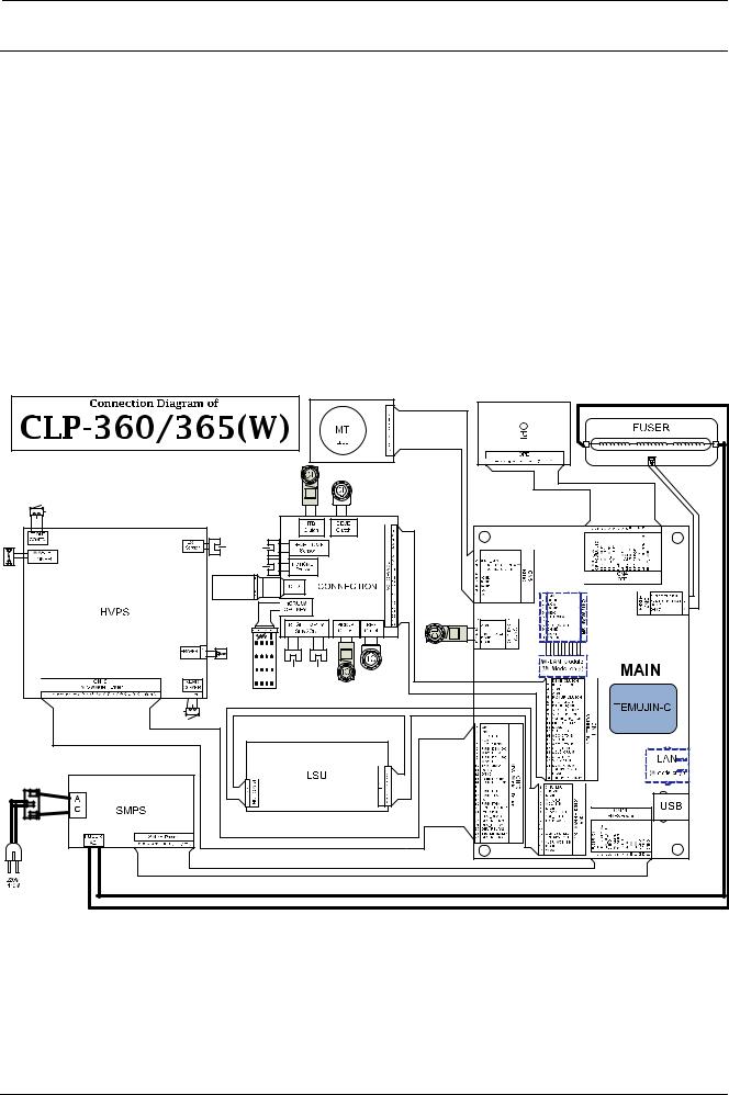
5.2. |
Connection Diagram................................................................................................................. |
5 |
− |
2 |
|
6. |
Reference Information........................................................................................................................ |
6 |
− |
1 |
||
|
6.1. |
Tool for Troubleshooting........................................................................................................... |
6 |
− |
1 |
|
|
6.2. |
Glossary |
................................................................................................................................. |
6 |
− |
2 |
|
6.3. |
Document ............................................................................................................Revision List |
6 |
− |
8 |
|
iii |
Copyright© 1995-2013 SAMSUNG. All rights reserved. |

1. Precautions
1. Precautions
In order to prevent accidents and damages to the equipment please read the precautions listed below carefully before servicing the product and follow them closely.
1.1. Safety warning
1)Only to be serviced by a factory trained service technician.
High voltages and lasers inside this product are dangerous. This product should only be serviced by a factory trained service technician.
2)Use only Samsung replacement parts.
There are no user serviceable parts inside the product. Do not make any unauthorized changes or additions to the product as these could cause the product to malfunctions and create an electric shocks or fire hazards.
3)Laser Safety Statement
The printer is certified in the U.S. to conform to the requirements of DHHS 21 CFR, chapter 1 Subchapter J for Class I(1) laser products, and elsewhere is certified as a Class I laser product conforming to the requirements of IEC 60825-1. Class I laser products are not considered to be hazardous. The laser system and printer are designed so there is never any human access to laser radiation above a Class I level during normal operation, user maintenance or prescribed service condition.
•Wavelength: 788 nm (-13/ +12)
•Beam divergence
-Paraller : 8 degrees (-2/ +4)
-Perpendicular: 31 degrees (-6/ +4)
•Maximum power of energy output: 12 mW
 WARNING
Never operate or service the product with the protective cover removed from Laser/Scanner assembly. The reflected beam, although invisible, can damage your eyes.
When using this product, these basic safety precautions should always be followed to reduce risk of fire, electric shock, and personal injury.
Copyright© 1995-2013 SAMSUNG. All rights reserved. |
1-1 |

1. Precautions
1.2. Caution for safety
1.2.1. Toxic material
This product contains toxic materials that could cause illness if ingested.
1)Please keep imaging unit and toner cartridge away from children. The toner powder contained in the imaging unit and toner cartridge may be harmful, and if swallowed, you should contact a doctor.
1.2.2. Electric shock and fire safety precautions
Failure to follow the following instructions could cause electric shock or potentially cause a fire.
1)Use only the correct voltage, failure to do so could damage the product and potentially cause a fire or electric shock.
2)Use only the power cable supplied with the product. Use of an incorrectly specified cable could cause the cable to overheat and potentially cause a fire.
3)Do not overload the power socket, this could lead to overheating of the cables inside the wall and could lead to a fire.
4)Do not allow water or other liquids to spill into the product, this can cause electric shock. Do not allow paper clips, pins or other foreign objects to fall into the product, these could cause a short circuit leading to an electric shock or fire hazard.
5)Never touch the plugs on either end of the power cable with wet hands, this can cause electric shock. When servicing the product, remove the power plug from the wall socket.
6)Use caution when inserting or removing the power cord. When removing the power cord, grip it firmly and pull. The power cord must be inserted completely, otherwise a poor contact could cause overheating leading to a fire.
7)Take care of the power cable. Do not allow it to become twisted, bent sharply around corners or power cable may be damaged. Do not place objects on top of the power cable. If the power cable is damaged it could overheat and cause a fire. Exposed cables could cause an electric shock. Replace the damaged power cable immediately, do not reuse or repair the damaged cable. Some chemicals can attack the coating on the power cable, weakening the cover or exposing cables causing fire and shock risks.
8)Ensure that the power sockets and plugs are not cracked or broken in any way. Any such defects should be repaired immediately. Take care not to cut or damage the power cable or plugs when moving the machine.
9)Use caution during thunder or lightning storms. Samsung recommends that this machine be disconnected from the power source when such weather conditions are expected. Do not touch the machine or the power cord if it is still connected to the wall socket in these weather conditions.
10)Avoid damp or dusty areas, install the product in a clean well ventilated location. Do not position the machine near a humidifier or in front of an air conditioner. Moisture and dust built up inside the machine can lead to overheating and cause a fire or cause parts to rust.
11)Do not position the product in direct sunlight. This will cause the temperature inside the product to rise possibly leading to the product failing to work properly and in extreme conditions could lead to a fire.
12)Do not insert any metal objects into the machine through the ventilator fan or other part of the casing, it could make contact with a high voltage conductor inside the machine and cause an electric shock.
13)When replacing the SMPS board, please wait 5 minutes after unplugging the power cord, then replace it. You can get a shock by the electric discharge.
1-2 |
Copyright© 1995-2013 SAMSUNG. All rights reserved. |

1. Precautions
1.2.3. Handling precautions
The following instructions are for your own personal safety to avoid injury and so as not to damage the product.
1)Ensure the product is installed on a level surface, capable of supporting its weight. Failure to do so could cause the product to tip or fall.
2)The product contains many rollers, gears and fans. Take great care to ensure that you do not catch your fingers, hair or clothing in any of these rotating devices.
3)Do not place any small metal objects, containers of water, chemicals or other liquids close to the product which if spilled could get into the machine and cause damage or a shock or fire hazard.
4)Do not install the machine in areas with high dust or moisture levels, beside on open window or close to a humidifier or heater. Damage could be caused to the product in such areas.
5)Do not place candles, burning cigarettes, etc on the product, These could cause a fire.
6)Ensure that the machine is installed and used in proper area to meet the temperature and humidity specifications.
•If the machine is stored at below zero Celsius for a long time, do not use the machine instantly after movement. It can malfunction. Take care of the machine storage. If the machine is stored at below zero Celsius for a long time, keep the machine at room temperature and install it.
1.2.4. Assembly and Disassembly precautions
1)Replace parts carefully and always use Samsung parts. Take care to note the exact location of parts and also cable routing before dismantling any part of the machine. Ensure all parts and cables are replaced correctly. Please carry out the following procedures before dismantling the product or replacing any parts.
2)Ensure that power is disconnected before servicing or replacing any electrical parts.
3)Disconnect interface cables and power cables.
4)Only use approved spare parts. Ensure that part number, product name, any voltage, current or temperature rating are correct.
5)When removing or re-fitting any parts do not use excessive force, especially when fitting screws into plastic.
6)Take care not to drop any small parts into the machine.
7)Handling of the OPC Drum
•The OPC Drum can be irreparably damaged if it exposed to light. Take care not to expose the OPC Drum either to direct sunlight or to fluorescent or incandescent room lighting. Exposure for as little as 5 minutes can damage the surface of the photoconductive properties and will result in print quality degradation. Take extra care when servicing the product. Remove the OPC Drum and store it in a black bag or other lightproof container. Take care when working with the Covers (especially the top cover) open as light is admitted to the OPC area and can damage the OPC Drum.
•Take care not to scratch the green surface of OPC Drum Unit. If the green surface of the Drum Cartridge is scratched or touched the print quality will be compromised.
Copyright© 1995-2013 SAMSUNG. All rights reserved. |
1-3 |

1. Precautions
1.2.5. Disregarding this warning may cause bodily injury
1)Be careful with the high temperature part.
The fuser unit works at a high temperature. Use caution when working on the printer. Wait for the fuser unit to cool down before disassembly.
2)Do not put fingers or hair into the rotating parts.
When operating a printer, do not put hand or hair into the rotating parts (Paper feeding entrance, motor, fan, etc.). If do, you can get harm.
3)When you move the printer, use safe lifting and handling techniques.
This printer is heavy. Use the lifting handles located on each side of the machine. Back injury could be caused if you do not lift carefully.
4)Ensure the printer is installed safely.
Ensure the printer is installed on a level surface, capable of supporting its weight. Failure to do so could cause the printer to tip or fall possibly causing personal injury or damaging the printer.
5)Do not install the printer on a sloping or unstable surface. After installation, double check that the printer is stable.
1-4 |
Copyright© 1995-2013 SAMSUNG. All rights reserved. |

1. Precautions
1.3. ESD precautions
Certain semiconductor devices can be easily damaged by static electricity. Such components are commonly called “Electrostatically Sensitive (ES) Devices” or ESDs. Examples of typical ESDs are: integrated circuits, some field effect transistors, and semiconductor “chip” components. The techniques outlined below should be followed to help reduce the incidence of component damage caused by static electricity.
 CAUTION
Be sure no power is applied to the chassis or circuit, and observe all other safety precautions.
1)Immediately before handling a semiconductor component or semiconductor-equipped assembly, drain off any electrostatic charge on your body by touching a known earth ground. Alternatively, employ a commercially available wrist strap device, which should be removed for your personal safety reasons prior to applying power to the unit under test.
2)After removing an electrical assembly equipped with ESDs, place the assembly on a conductive surface, such as aluminum or copper foil, or conductive foam, to prevent electrostatic charge buildup in the vicinity of the assembly.
3)Use only a grounded tip soldering iron to solder or desolder ESDs.
4)Use only an “anti-static” solder removal device. Some solder removal devices not classified as “anti-static” can generate electrical charges sufficient to damage ESDs.
5)Do not use Freon-propelled chemicals. When sprayed, these can generate electrical charges sufficient to damage ESDs.
6)Do not remove a replacement ESD from its protective packaging until immediately before installing it. Most replacement ESDs are packaged with all leads shorted together by conductive foam, aluminum foil, or a comparable conductive material.
7)Immediately before removing the protective shorting material from the leads of a replacement ESD, touch the protective material to the chassis or circuit assembly into which the device will be installed.
8)Maintain continuous electrical contact between the ESD and the assembly into which it will be installed, until completely plugged or soldered into the circuit.
9)Minimize bodily motions when handling unpackaged replacement ESDs. Normal motions, such as the brushing together of clothing fabric and lifting one’s foot from a carpeted floor, can generate static electricity sufficient to damage an ESD.
Copyright© 1995-2013 SAMSUNG. All rights reserved. |
1-5 |
2. Product specification and description
2. Product specification and description
2.1. Product Specification
2.1.1. Product Overview
1)Printing Speed
•18 (Mono) / 4 (Color) ppm in A4 (19/4 ppm in Letter)
2)Processor
•300 MHz
3)Printer Language
•SPL-C
4)Memory
•32MB (Standard) / 32MB (Max)
5)Interface
•High Speed USB 2.0
•10/100 BaseTX network connector (CLP-36xW only)
•802.11b/g/n wireless LAN (CLP-36xW only)
6)Toner cartridge
•Initial : 700 (K)/ 500 (CMY) pages
•Sales: 1,500 (K)/ 1,000 (CMY) pages
2-1 |
Copyright© 1995-2013 SAMSUNG. All rights reserved. |
2. Product specification and description
2.1.2. Specifications
 NOTE
NOTE
Product Specifications are subject to change without notice.
2.1.2.1. General Print Engine
Item |
Specification |
||
|
Simplex (C/M) |
• Mono : 19 ppm @Letter, 18 ppm @A4 |
|
Engine Speed |
• Color : 4 ppm @Letter, A4 |
||
|
|||
|
Duplex |
N/A |
|
|
|
|
|
FPOT |
From Ready (C/M) |
Less than 26/14 sec |
|
|
|
||
From Sleep (C/M) |
Less than 29.5/29.5 sec |
||
|
|||
|
|
|
|
Resolution |
• Best 600x600 2bit (Default) |
||
• Normal 600x600 1bit |
|||
|
|
||
|
|
|
|
2.1.2.2. Controller and Software
Item |
|
Specification |
|
Processor |
|
Samsung 300MHz |
|
|
|
|
|
Memory |
Std. |
32 MB |
|
|
|
||
Max. |
32 MB |
||
|
|||
|
|
|
|
Printer Languages |
|
SPL-C |
|
|
|
|
|
Fonts |
|
Windows fonts |
|
|
|
|
|
|
Default Driver |
SPL-C |
|
|
|
|
|
|
|
[WINDOW] |
|
|
|
• Windows XP/2003/Vista/2008, Windows 7/2008 R2 |
|
|
|
|
|
|
|
[Linux] |
|
|
|
• RedHat Enterprise Linux WS 4, 5 (32/64 bit) |
|
|
|
• Fedora 5, 6, 7, 8, 9, 10, 11, 12, 13 (32/64 bit) |
|
|
|
• SuSE Linux 10.1 (32 bit) |
|
Printer Driver |
Supporting OS |
• OpenSuSE 10.2, 10.3, 11.0, 11.1, 11.2 (32/64 bit) |
|
|
|
• Mandriva 2007, 2008, 2009, 2009.1, 2010 (32/64 bit) |
|
|
|
• Ubuntu 6.06, 6.10, 7.04, 7.10, 8.04, 8.10, 9.04, 9.10, 10.04 (32/64 |
|
|
|
bit) |
|
|
|
• SuSE Linux Enterprise Desktop 10, 11 (32/64 bit) |
|
|
|
• Debian 4.0, 5.0 (32/64 bit) |
|
|
|
|
|
|
|
Mac OS X 10.4~10.7 |
|
|
|
|
|
|
WHQL |
Windows XP/2003/Vista, Windows 7 |
|
|
|
|
Copyright© 1995-2013 SAMSUNG. All rights reserved. |
2-2 |

2. Product specification and description
Item |
|
Specification |
||
|
|
• |
CLP-36x : N/A |
|
|
|
• |
CLP-36xW |
|
|
Protocol |
|
• TCP/IPv4/IPv6, Standard TCP/IP printing, LPR, IPP, |
|
|
|
|
SNMPv1/2/3, HTTP, SLP, Bonjour |
|
|
|
|
|
|
|
|
|
• Authentication : WPA2 personal (PSK) |
|
|
|
|
• |
Encryption : WEP,TKIP,AES |
|
|
|
||
|
|
• Windows : 7/XP (32/64 bit)/2003 Server (32/64 bit)/Vista (32/64 |
||
|
|
|
bit) |
|
|
|
• MAC OS X : 10.3 ~ 5 (TCP/IP Only) |
||
Network Interface |
|
• |
Linux(Printer only)OS : |
|
|
|
|
• |
Fedora 2,~9 (32/6b4it) |
|
|
|
• openSuSE 9.1, 9.2, 9.3, 10.0, 10.1, 10.2, 10.3, 11.0 (32/64bit) |
|
|
Network OS |
|
• Ubuntu 6.04, 6.10, 7.04, 7.10, 8.04 (32/64bit) |
|
|
|
|
• Mandriva 10.0, 10.1, 2005, 2006, 2007, 2008 (32/64bit) |
|
|
|
|
• Debian 3.1, 4.0 (32/64bit) |
|
|
|
|
• Redhat Enterprise Linux WS 4, 5 (32/64bit) |
|
|
|
|
• SuSE Linux Enterprise Desktop 9, 10 (32/64bit) |
|
|
|
• Novell : NetWare 5.x, 6.x (TCP/IP Only) |
||
|
|
• Others : Unix HP-UX, Solaris, SunOS, SCO UNIX |
||
|
|
|
|
|
Application |
Easy Printer Manager |
YES |
|
|
|
|
|
||
|
Network Management |
Set IP, SWAS 5.0 & SWS 2.0 |
||
|
(Linux, Mac not support, SWAS&SWS need I explorer 5.0 or Higher) |
|||
|
|
|||
|
|
|
|
|
■ Interface
Item |
|
Specification |
|
Parallel |
Option Interface |
N/A |
|
|
|
|
|
USB |
High Speed USB 2.0 |
USB Host 2.0 |
|
|
|
|
|
Wired Network |
|
• |
CLP-36x : N/A |
|
• CLP-36xW : Ethernet 10/100 base Tx |
||
|
|
||
|
|
|
|
Wireless Network |
|
• |
CLP-36x : N/A |
|
• |
CLP-36xW : 802.11b/g/n |
|
|
|
||
|
|
|
|
2.1.2.3. Paper Handling
Item |
Specification |
|||
Standard Capacity |
• 130-sheet Cassette Tray @80g/m² |
|||
|
|
|
||
Printing |
Max. Size |
216 x 356 mm (8.5" x 14") |
||
|
|
|
||
Min. Size |
76 x 152.4 mm (3.0" x 6.0") |
|||
|
||||
|
|
|
|
|
Multi-purpose tray |
N/A |
|
||
|
|
|
|
|
|
|
• |
130 sheets @80g/m² |
|
Standard Cassette Tray |
Capacity |
• |
Label , thick paper : 5 Sheets |
|
|
|
• Glossy Photo 220g/m² : 1 Sheets |
||
|
|
|
|
|
2-3 |
Copyright© 1995-2013 SAMSUNG. All rights reserved. |

2. Product specification and description
Item |
Specification |
||
|
Media sizes |
A4, A5,A6, Letter, Legal, Executive, Folio, ISO B5, JIS B5 Glossy Photo |
|
|
220g/m² |
||
|
|
||
|
|
|
|
|
|
• |
Plain : 60 ~ 85g/m² |
|
Media weight |
• |
Thick Paper: 86 ~ 120g/m² |
|
• |
Cardstock: 121 ~ 163g/m² |
|
|
|
||
|
|
• |
Photo : 220g/m² |
|
|
|
|
Option Cassette (SCF) |
N/A |
|
|
|
|
|
|
Output Stacking |
Capacity |
50 sheets @80g/m² |
|
|
|
|
|
Output Full sensing |
Yes |
|
|
|
|
||
|
|
|
|
2.1.2.4. Reliability and Service
Item |
Specification |
Average Monthly Volume |
Color 46 pages, Mono 140 pages |
|
|
Max. Monthly Duty |
20,000 images |
|
|
2.1.2.5. Environment
Item |
|
Specification |
||
Temperature |
Operation |
10 to 32°C (50 to 89.6°F) |
||
|
|
|
||
Humidity |
Operation |
20 to 80% RH |
||
|
|
|
||
Acoustic Noise |
Ready mode |
Background Level |
||
|
|
|
||
Level(Sound |
Print mode |
• |
color printing: Less than 45 dB (A) |
|
Power/Pressure) |
• black and white printing: Less than 48 dB (A) |
|||
|
||||
|
|
|||
|
|
|
|
|
|
Average operating |
Less than 290 W |
||
|
mode |
|||
|
|
|
||
|
|
|
||
Power Consumption |
Ready mode |
Less than 60 W |
||
|
|
|
||
Power save mode |
• |
CLP-36x Series: Less than 1.0 W |
||
|
||||
|
• |
CLP-36xW Series: Less than 1.8 W |
||
|
|
|||
|
|
|
||
|
Power off mode |
Less than 0.45 W |
||
|
|
|
||
Dimension (W x D x H) |
|
382 x 309 x 211 mm (15.0 x 12.2 x 8.3 inch) (except paper tray) |
||
|
|
|
||
Weight |
Machine with |
10.3 kg (22.7 lb) |
||
consumables |
|
|
||
|
|
|
||
|
|
|
|
|
Copyright© 1995-2013 SAMSUNG. All rights reserved. |
2-4 |

2. Product specification and description
2.1.2.6. Consumables
Item |
Specification |
|||
|
|
• |
K406(CLT-K406S) : Black |
|
|
Model |
• |
C406(CLT-Y406S) : Yellow |
|
|
• |
M406(CLT-M406S) : Magenta |
||
|
|
|||
Toner Cartridge |
|
• |
Y406(CLT-C406S) : Cyan |
|
|
|
|
||
|
• Average continuous black cartridge yield: Apporx. 1,500 standard |
|||
|
|
|||
|
Yield* |
|
pages (Black) |
|
|
• Average continuous color cartridge yield: Apporx. 1,000 standard |
|||
|
|
|||
|
|
|
pages (Yellow/Magenta/Cyan) |
|
|
|
|
||
Imaging Unit |
Model |
CLT-R406 |
||
|
|
|
||
Yield* |
Approx. 16,000 images** |
|||
|
||||
|
|
|
||
Waste Toner Container |
Model |
CLT-W406 |
||
|
|
|
||
Yield* |
Approx. 7,000 images** |
|||
|
||||
|
|
|
|
|
 NOTE
NOTE
*Declared yield value in accordance with ISO/IEC 19798. The number of pages may be affected by operating environment, printing interval, graphics, media type and media size.
**Image counts based on one color on each page. If you print documents in full color (Cyan, Magenta, Yellow, Black), the life of this item will be reduced by 25%.
2.1.2.7.Maintenance Parts
Item |
|
Specification |
|
Transfer roller Assy |
Part Code |
JC93-00708A |
|
|
|
|
|
|
Life |
20,000 pages |
|
|
|
|
|
Fuser unit |
Part Code |
• |
JC91-01138A (220V) |
|
|
• |
JC91-01137A (110V) |
|
|
|
|
|
Life |
Approx. 20,000 images B&W or 5,000 images Color |
|
|
|
|
|
Pick-Up roller |
Part Code |
JC73-00309A |
|
|
|
|
|
|
Life |
20,000 pages |
|
|
|
|
|
ITB unit |
Part Code |
JC96-06292A |
|
|
|
|
|
|
Life |
Approx. 20,000 images B&W or 5,000 images Color |
|
|
|
|
|
2-5 |
Copyright© 1995-2013 SAMSUNG. All rights reserved. |

|
|
|
2. Product specification and description |
|
2.1.3. Model Comparison Table |
|
|
|
|
|
|
|
|
|
|
Samsung CLP-365W |
Samsung CLP-325W |
|
HP CP1525n |
Image |
|
|
|
|
|
|
|
|
|
Mono/Color Speed |
18 / 4 ppm |
16 / 4 ppm |
|
12 / 8 ppm |
(A4) |
|
|
|
|
|
|
|
|
|
Processor |
300 MHz |
375 MHz |
|
264 MHz |
|
|
|
|
|
Memory (Std/ Max) |
32 MB / 32 MB |
32 MB / 256 MB |
|
128 MB / 384 MB |
|
|
|
|
|
Print Language |
SPL-C |
SPL-C |
|
HP PCL 6 |
|
|
|
|
|
Paper Input |
130 sheets Cassette |
150 sheets Cassette |
|
150 sheets Cassette |
|
|
|
|
|
Duplex |
N/A |
N/A |
|
N/A |
|
|
|
|
|
Interface |
High Speed USB 2.0 |
High Speed USB 2.0 |
|
High Speed USB 2.0 |
|
10/100 Base TX |
10/100 Base TX |
|
10/100 Base TX |
|
IEEE 802.11 b/g/n |
IEEE 802.11 b/g/n |
|
|
|
|
|
|
|
Size (mm) |
382 x 309 x 211 mm |
388 x 313 x 243 mm |
|
399 x 505 x 254 mm |
|
|
|
|
|
Toner Cartridge |
1.5K / 1K |
1.5K / 1K |
|
2K / 1.3K |
(K/CMY) |
|
|
|
|
|
|
|
|
|
Copyright© 1995-2013 SAMSUNG. All rights reserved. |
2-6 |
2. Product specification and description
2.2. System Overview
This chapter describes the functions and operating principal of the main component.
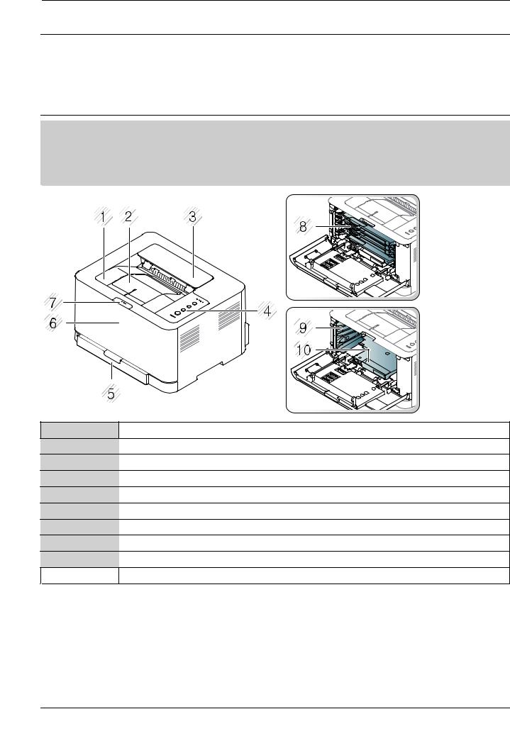
2.2.1. Front View
 NOTE
NOTE
•This illustration may differ from your machine depending on your model. There are various types of machine.
•Some features and optional goods may not be available depending on model or country.
1Output tray
2Output support
3Top cover
4Control Panel
5Tray
6Front cover
7Front cover release button
8Toner cartridges
9Waster toner container
10 |
Imaging unit |
|
|
2-7 |
Copyright© 1995-2013 SAMSUNG. All rights reserved. |
2. Product specification and description
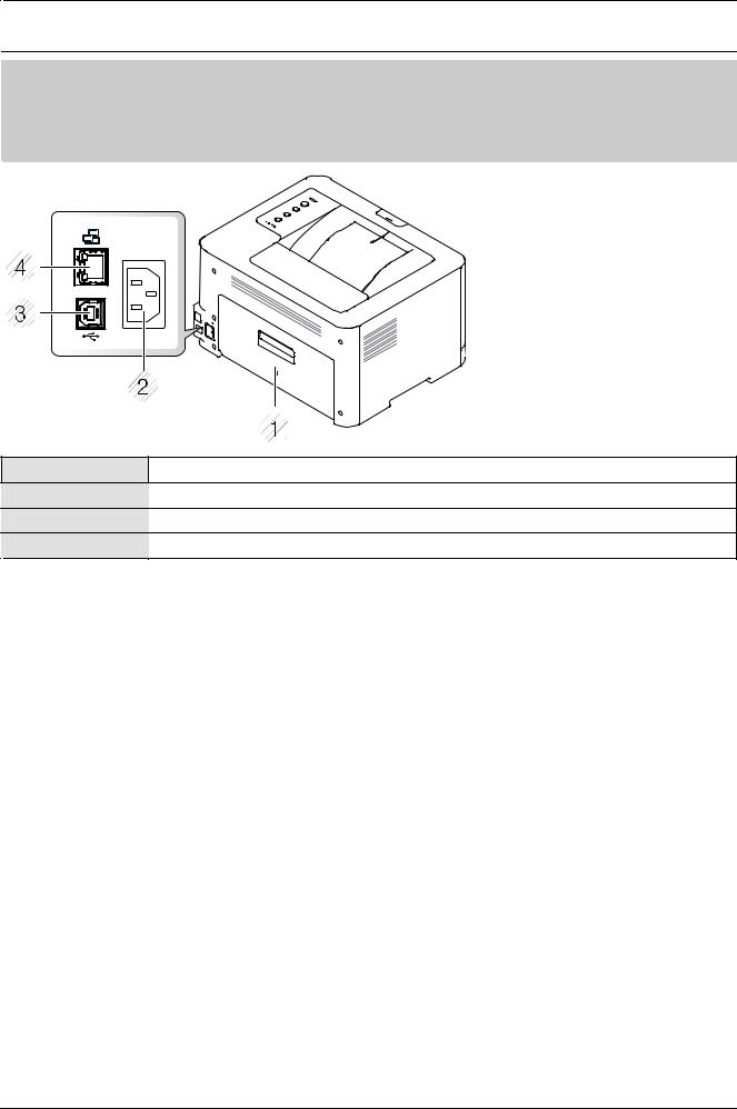
2.2.2. Rear View
 NOTE
NOTE
•This illustration may differ from your machine depending on your model. There are various types of machine.
•Some features and optional goods may not be available depending on model or country.
1Rear cover
2Power receptacle
3USB port
4Network port (CLP-36xW only)
Copyright© 1995-2013 SAMSUNG. All rights reserved. |
2-8 |
2. Product specification and description
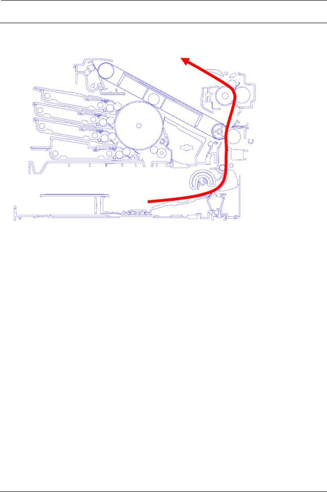
2.2.3. Paper Path
The following diagram displays the path the paper follows during the printing process.
2-9 |
Copyright© 1995-2013 SAMSUNG. All rights reserved. |
2. Product specification and description
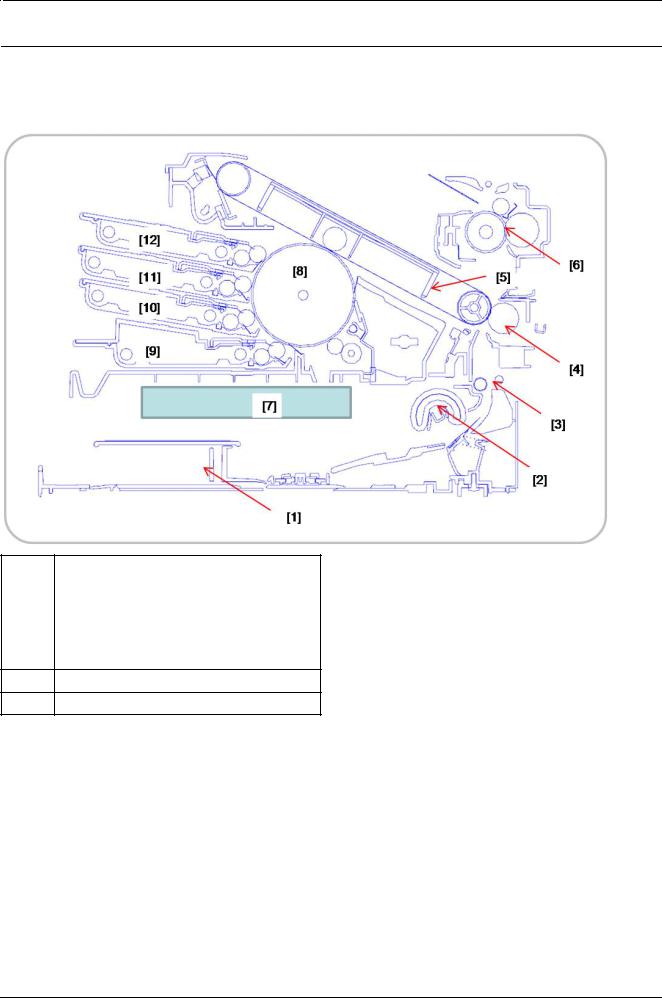
2.2.4. System Layout
This model consists of the engine parts, hardware parts, firmware. The engine parts consists of the mechanical parts comprising Frame, Toner Cartridge, Drive Unit, Transfer roller, Pick up unit, Fuser, Cassette. The hardware parts consists of the main board, SMPS, HVPS board, OPE board, PC interface.
1 |
Cassette |
|
8 |
OPC drum |
|
|
|
|
|
2 |
Pick up roller |
|
9 |
K toner cartridge |
|
|
|
|
|
3 |
Registration roller |
|
10 |
C toner cartridge |
|
|
|
|
|
4 |
Transfer(T2) roller |
|
11 |
M toner cartridge |
|
|
|
|
|
5 |
ITB Unit |
|
12 |
Y toner cartridge |
|
|
|
|
|
6Fuser Unit
7LSU
Copyright© 1995-2013 SAMSUNG. All rights reserved. |
2-10 |
2. Product specification and description
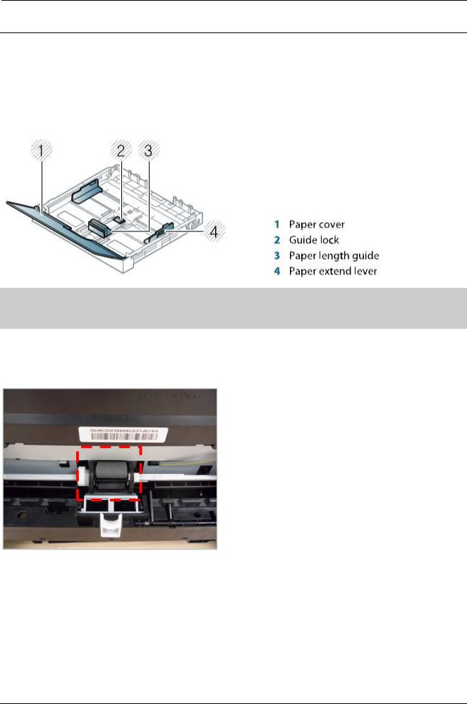
2.2.4.1. Feeding Section
It is consists of a basic cassette, pick up/forward/retard roller and parts related to paper transferring.
1) Cassette (Tray1)
This model has a cassette type tray.
It has a paper existence sensing function, paper arranging function.
 NOTE
NOTE
If you do not adjust the guide, it may cause paper registration, image skew, or jamming of the paper.
2) Pick up roller
This roller has functions such as a paper pickup function, paper feeding function, and removing electronic static function. Pick up roller is driven by solenoid.
2-11 |
Copyright© 1995-2013 SAMSUNG. All rights reserved. |
2. Product specification and description
2.2.4.2. Transfer Roller
The transfer roller unit is assembled to the rear of the machine. The transfer roller delivers the toner of the OPC drum to the paper.
2.2.4.3. Drive Unit
The Drive unit is assembled to the right frame. It consists of a BLDC motor, a clutch, and various gears.
Copyright© 1995-2013 SAMSUNG. All rights reserved. |
2-12 |
2. Product specification and description
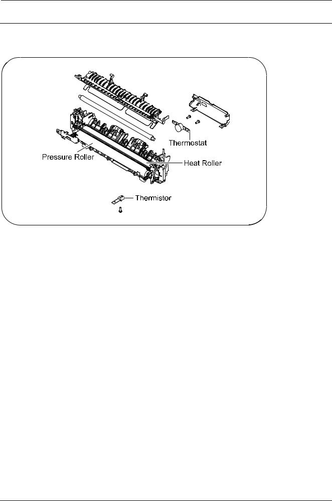
2.2.4.4. Fuser Unit
This unit consists of Heat Roller, a Thermostat, and Thermistor, etc. It fuses the toner that was transferred by the transfer roller onto the paper, by applying heat and pressure to complete fusing process.
1)Thermostat
When a heat lamp is overheated, a Thermostat cuts off the main power to prevent overheating.
•Thermostat Type : NonContact type Thermostat
•Control Temperature : 195°C ± 5°C
2)Thermistor
It is a temperature detecting sensor.
•Temperature Resistance : 7 kΩ(180°C)
3)Heat roller
The heat roller transfers the heat from the lamp to apply a heat on the paper.
The surface of a heat roller is coated with Teflon, so toner does not stick to the surface.
4)Pressure roller
A pressure roller mounted under a heat roller is made of a silicon resin, and the surface also is coated with Teflon. When a paper passes between a heat roller and a pressure roller, toner adheres to the surface of a paper and is permanently fused.
5)Halogen Lamp
•Voltage : 120 V (115 ± 5 %) / 220 V : 230 ± 5 %
•Capacity : 850 Watt ± 25 W
2-13 |
Copyright© 1995-2013 SAMSUNG. All rights reserved. |
2. Product specification and description
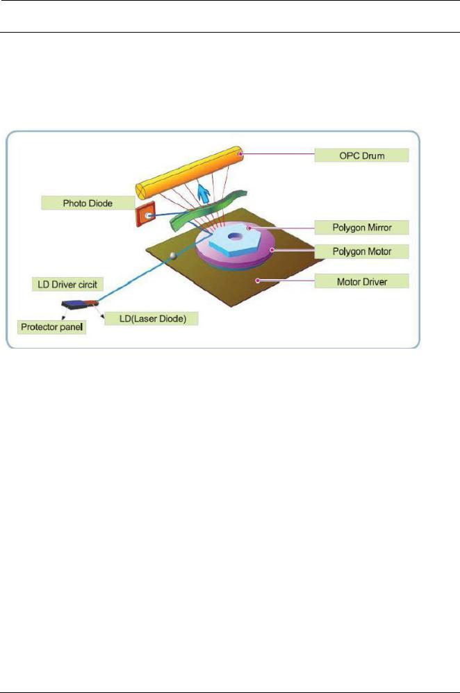
2.2.4.5. LSU (Laser Scanner Unit)
It is the core part of the LBP ( Laser Beam Printer ) which switches from the video data received to the controller to the electrostatic latent image on the OPC drum by controlling laser beam, exposing OPC drum, and turning principle of polygon mirror. The OPC drum is turned with the paper feeding speed. The HSYNC signal is created when the laser beam from LSU reaches the end of the polygon mirror, and the signal is sent to the controller. The controller detects the HSYNC signal to adjust the vertical line of the image on paper. In other words, after the HSYNC signal is detected, the image data is sent to the LSU to adjust the left margin on paper. The one side of the polygon mirror is one line for scanning.
Copyright© 1995-2013 SAMSUNG. All rights reserved. |
2-14 |
2. Product specification and description
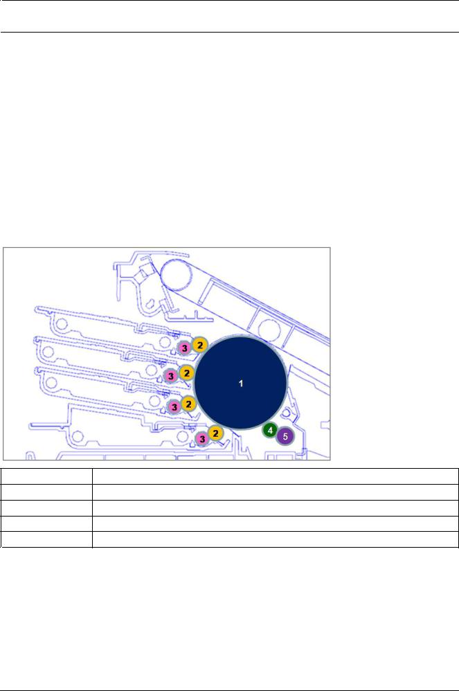
2.2.4.6. Toner Cartridges and Imaging Unit
By using the electronic photo process, they creates a visual image. The toner cartridge consists of the supply roller and developing roller. The imaging unit consists of the OPC drum, charge roller, cleaning roller.
•Developing Method : Non magnetic single component non-contacting method
•Toner : Non magnetic single component pulverized type toner
•The life span of toner (ISO 19798 pattern / A4 standard)
-1.5K (K) / 1K (CMY)
•The life span of imaging unit
-Approx. 16,000 images.
•OPC Cleaning : Collect the toner by using cleaning blade
•Handling of wasted toner : Collect the wasted toner in the cleaning frame by using cleaning blade
•Classifying device for toner cartridge: ID is classified by CRUM
1OPC drum
2Developing Roller
3Supply Roller
4Charge Roller
5Cleaning Roller
2-15 |
Copyright© 1995-2013 SAMSUNG. All rights reserved. |
2. Product specification and description
2.2.5. Hardware configuration
The CLP-36x series Electrical Circuit System consists of the following:
•Main board (System board)
•OPE board
•Connection board
•CTD board
•CRUM Joint board
•SMPS board
•HVPS board
•WLAN board (Wireless model only)
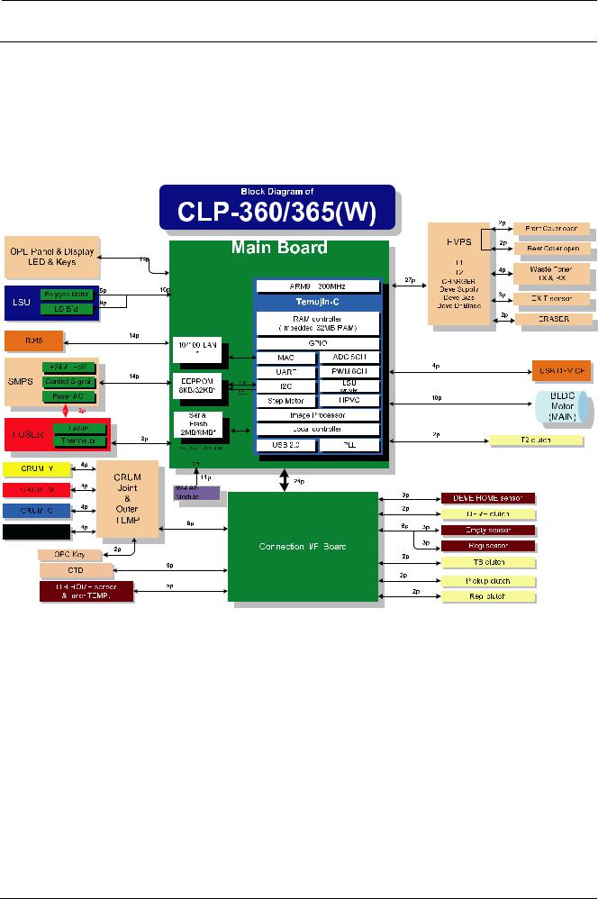
Diagram of the CLP-36x series Electrical Circuit
CLX-330x series has a system board of integrated engine controller, video controller.
The engine controller controls all modules required to print, that is, LSU, HVPS/SMPS, Fuser, Motor etc. It communicates with the video control block inside CPU for printing. And it has the interface for all video sync signal to print out
the video data.
The video controller receives print data from the host through network or USB Port. It takes this information and generates printable video bitmap data.
Copyright© 1995-2013 SAMSUNG. All rights reserved. |
2-16 |
2. Product specification and description
The main board is adopted 300 MHz Temujin-C CPU that is integrated with engine/ video controller. It has the SDRAM internal memory 32MByte.
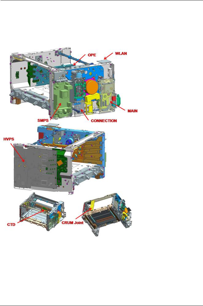
Circuit board locations
The following diagrams show the locations of the printer circuit boards:
2-17 |
Copyright© 1995-2013 SAMSUNG. All rights reserved. |
2. Product specification and description
2.2.5.1. Main board
The Temujin-C chip is adopted as the main processor. Its process speed is 300 MHz. It is integrated engine controller, video controller.
There is a SDRAM 32Mbyte in the Temujin-C chip.
USB is the embedded type and wired network supports 100M full duplex.
[Main board diagram]
Copyright© 1995-2013 SAMSUNG. All rights reserved. |
2-18 |

2. Product specification and description
[Main board image]
•Connection
1LSU connector
2Connection board connector
3HVPS interface connector
4USB device connector
5Fuser thermistor interface connector
6OPE connector
7Main BLDC Motor connector
8T2 Clutch connector
9SMPS interface connector
10Wired network connector (W model only)
11Wireless module interface connector(W model only)
12Debugger connector(will be deleted)
•Information
-Part Code
▪JC92-02485A (CLP-360/365 Model)
▪JC92-02483A (CLP-360W/365W Model)
-Part Name : PBA-MAIN
2-19 |
Copyright© 1995-2013 SAMSUNG. All rights reserved. |
2. Product specification and description
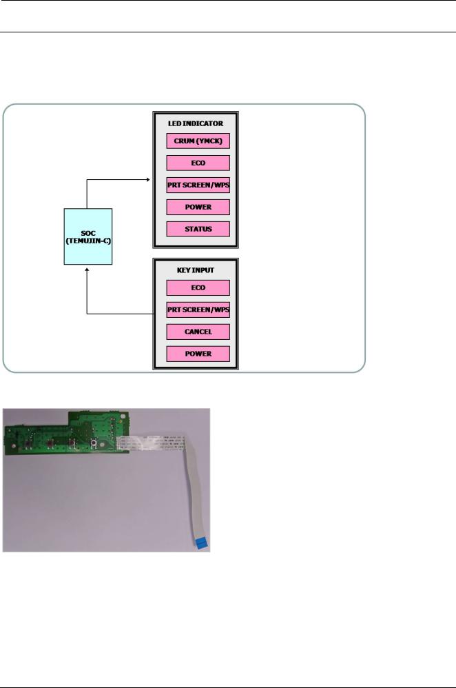
2.2.5.2. OPE board
The OPE board receives information from key input and send it to the main board. The main board controls the LED on OPE board.
[OPE controller diagram]
[OPE controller image]
•Information
-Part Code
▪JC92-02500A (CLP-360/365 Model)
▪JC92-02501A (CLP-360W/365W Model)
-PBA Name : PBA-OPE
•Connection
1 |
Interface connector to Main board |
|
|
Copyright© 1995-2013 SAMSUNG. All rights reserved. |
2-20 |
2. Product specification and description
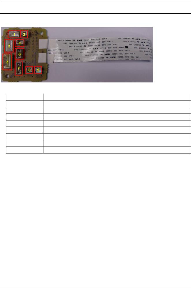
2.2.5.3. Connection board
This board connects between the cluth/sensor/CRUM I/F board and the main board.
•Connection
1ITB Clutch
2DEVE Clutch
3ITB I/F
4DEVE Home Sensor
5Crum I/F board
6CTD
7Regi/Empty Senor
8Regi Clutch
9Pickup Clutch
•Information
-Part Code : JC92-02489A
-Part Name : PBA-CONNECTOR
2-21 |
Copyright© 1995-2013 SAMSUNG. All rights reserved. |
Loading...