


Alignment and Adjustments
4. Alignment and Adjustments
4-1 General Alignment Instructions
1.Usually, a color TV-VCR needs only slight touch-up adjustment upon installation. Check the basic characteristics such as height, horizontal and vertical sync and focus.
2.Observe the picture for good black and white details. There should be objectionable color shading; if color shading is present, demagnetize, perform purity and convergence adjustments described below.
3.Use the specified test equipment or its equivalent.
4.Correct impedance matching is essential.
5.Avoid overload. Excessive signal from a sweep generator might overload the front-end of the TV. When inserting signal markers, do not allow the marker generator to distort test results.
6.Connect the TV only to an AC power source with voltage and frequency as specified on the backcover nameplate.
7.Do not attempt to connect or disconnect any wires while the TV is turned on. Make sure that the power cord is disconnected before replacing any parts.
8.To protect against shock hazard, use an isolation transformer.
4-2 Automatic Degaussing
A degaussing coil is mounted around the picture tube, so that external degaussing after moving the TV should be unnecessary. But the receiver must be properly degaussed upon installation.
The degaussing coil operates for about 1 second after the power is switched ON. If the set is moved or turned in a different direction, the power should be OFF for at least 10 minutes.
If the chassis or parts of the cabinet become magnetized, poor color purity will result. If this happens, use an external degaussing coil. Slowly move the degaussing coil around the faceplate of the picture tube and the sides and front of the receiver. Slowly withdraw the coil to a distance of about 6 feet before turning power OFF.
If color shading persists, perform the following Color purity and Convergence adjustments.
4-3 High Voltage Check
CAUTION : There is no high voltage adjustment on this chassis. The B+ power supply should be +135 volts (with full colorbar input and normal picture level).
1.Connect a digital voltmeter to the second anode of the picture tube.
2.Turn on the TV. Set the Brightness and Contrast controls to minimum (zero beam current).
3.Adjust the Brightness and contrast controls to both extremes. Ensure that the high voltage does not exceed 30 KV under any conditions.
Samsung Electronics |
4-1 |

Alignment and Adjustments
4-4 FOCUS Adjustment
1.Input a black and white signal.
2.Adjust the tuning control for the clearest picture.
3.Adjust the FOCUS control for well defined scanning lines in the center area of the screen.
4-5 SCREEN Adjustment
1.Input Toshiba Pattern
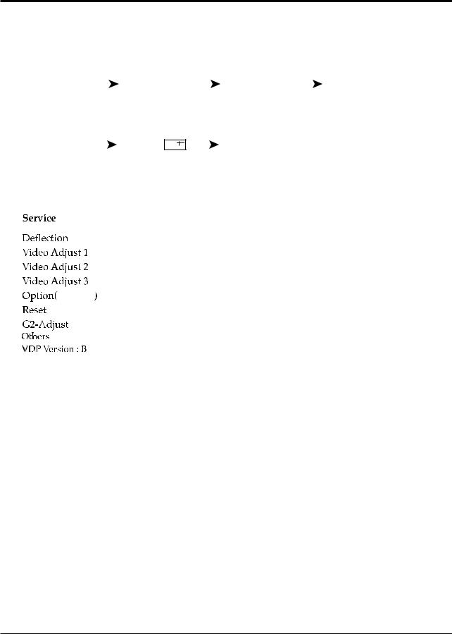
2.Enter “Service Mode”.(Refer to “4-8-1 Service Mode”)
3.Select “G2-Adjust”.
4.Set the values as below.
Table 1. Screen Adjustment Table
No |
INCH / CRT |
IBRM |
WDRV |
CDL |
COLR G B |
REGION |
|
(Smallest Value) |
|||||||
|
|
|
|
|
|
||
|
|
|
|
|
|
|
|
1 |
14” / SDI |
205 |
35 |
100 |
100 |
|
|
|
|
|
|
|
|
|
|
2 |
15PF / SDI |
220 |
35 |
180 |
100 |
|
|
|
|
|
|
|
|
|
|
3 |
21” 1.7R / SDI |
220 |
35 |
180 |
100 |
|
|
|
|
|
|
|
|
|
|
4 |
20V 10.0R/SDI |
205 |
35 |
115 |
120 |
|
|
|
|
|
|
|
|
Normal |
|
5 |
21PF / TSB |
220 |
35 |
180 |
65 |
||
|
|||||||
|
|
|
|
|
|
|
|
6 |
21PF / LG |
230 |
35 |
230 |
65 |
|
|
|
|
|
|
|
|
|
|
7 |
21PF / SDI |
220 |
35 |
210 |
65 |
|
|
|
|
|
|
|
|
|
|
8 |
25PF / SDI |
210 |
35 |
160 |
120 |
|
|
|
|
|
|
|
|
|
|
9 |
27V 1.3R / SDI |
210 |
35 |
170 |
150 |
|
|
|
|
|
|
|
|
|
|
10 |
27V 1.0R/SDI |
210 |
35 |
150 |
180 |
|
|
|
|
|
|
|
|
|
|
11 |
25V 1.0R/SDI |
210 |
35 |
150 |
180 |
|
|
|
|
|
|
|
|
|
|
12 |
23V 1.3R/SDI |
205 |
35 |
120 |
140 |
|
|
|
|
|
|
|
|
|
5.Turn the SCREEN VR until “MRCR G B” and “MRWDG” are green and those value are about 100. (The incorrect SCREEN Voltage may result that “MRCR G B” and “MRWDG” should be red)
4-2 |
Samsung Electronics |

Alignment and Adjustments
4-6 E2PROM (IC902) Replacement
1.When IC902 is replaced, all adjustment data revert to the initial values. So, all adjustment values when servicing should be readjusted.
2.After IC902 is replaced, connect the AC power supply cord.
3.Turn the power switch ON.
4.In stand-by, warm up the TV for at least 10 seconds.
5.Power on the TV.
4-7 White Balance Adjustment
■Equipment : Color-Analyzer (CA-100)
■Input Signal : Pattern signal (Toshiba pattern)
1.Select STANDARD from the menu.
2.Input an 100% White pattern.
3.Enter the “Service Mode”. (Refer to “4-8 Service Mode”)
4.Warm up the TV set at least for 30 minutes.
5.Input a Toshiba pattern signal.
6.Enter the “Video Adjust1”.
-Adjust “Sub Contrast” so that Y (luminance) becomes 65 ft ± 3.
-Use “Red Drive” and “ Blue Drive” to adjust High-Light (x : 265, y : 265)
-Adjust “Sub Bright” so that Y (luminance) becomes 1.2ft ± 0.3.
-Use “Red Cutoff” and “Blue Cutoff” to adjust Low-Light (x : 265, y : 265).
7.Adjust CA-100 so that the final adjustment value can be fixed.
8.Use the Channel Up/Down (▲/▼) buttons to move the cursor on the adjustment modes.
9.Use the Volume +/- buttons to change the adjustment value.
Samsung Electronics |
4-3 |
Alignment and Adjustments
4-8 Factory Adjustment
4-8-1 Service Mode
1.To enter the “Service Mode”, Press the remote-control keys in this sequence : - If you do not have Factory remote-control
|
PICTURE OFF |
|
|
|
|
MUTE |
|
|
|
|
1,8,2 |
|
|
|
PICTURE ON |
|
|
|
|
|
|
|
|||||||||||
|
|
|
|
|
|
|
|
|
|
|
|
|
|
|
||
- If you have Factory remote-control |
|
|
|
|
|
|
|
|
|
|||||||
|
|
|
|
|
|
|
|
|
|
|
|
|
|
|
|
|
|
PICTURE ON |
|
|
|
|
|
DISPLAY ( |
) |
|
|
|
FACTORY |
|
|
|
|
|
|
|
|
|
|
|
|
|
|
|
||||||
|
|
|
|
|
|
|
|
|
|
|
|
|
|
|
|
|
|
|
|
|
|
|
|
|
|
|
|
|
|
|
|
|
|
2. After the Service Mode is entered, the initial screen is as shown in the figure below.
xx xx xx * |
These hexa digits are check sum value which |
* depends on the MICOM version. |
|
|
If check sum value is changed, the value of |
|
E2PROM Data newly initialed. |
|
|
3.Use the Channel Up/Down buttons to move the cursor in the adjustment parameters.
Note :
-When CRT, CRT PCB, FBT, E2PROM (sometimes MICOM) is replaced, the adjustment values should be controlled.
-After the Service adjustment is completed, Do not select “Reset” in the service mode menu. (After above procedure is done, power is on initially and the “Plug and Play” will be operated.)
4-4 |
Samsung Electronics |

Alignment and Adjustments
4-8-2 Deflection (Memory Data)
- SIM408A USA, LATIN FACTORY (VDP IC VDP3108B)
4-8-2(A) GEOMETRIC ADJUSTMENT VALUE
|
|
INCH |
|
27V 1.3R |
23V 1.3R |
25V 1R |
27V 1R |
20V 1R |
15" FLAT |
|
|
|
|
|
|
TXK2550 |
TXK2750 |
TXK2060 |
|
|
Model |
|
|
|
TXK2554 |
|
|||
|
|
TXK2767 |
CL25D4W |
TXK2066 |
CT-15A8 |
||||
|
|
TXK2566 |
TXK2754 |
||||||
|
|
|
|
|
|
TXK2067 |
|
||
|
|
|
|
|
|
TXK2567 |
|
|
|
|
|
|
|
|
|
|
|
|
|
|
|
|
|
|
|
CL663BW |
|
|
|
DEFLECTION |
|
INIT |
|
|
|
|
|
|
|
|
|
|
|
|
|
|
|
||
H Bow |
|
0 |
FIX |
0 |
0 |
0 |
0 |
0 |
0 |
H Angle |
|
0 |
FIX |
0 |
0 |
0 |
0 |
0 |
0 |
H Dscc |
|
0 |
FIX |
3 |
3 |
3 |
3 |
3 |
3 |
V SHIFT |
|
-40 |
Control |
-27 |
-24 |
-18 |
-18 |
-40 |
-35 |
V AMP |
|
5 |
Control |
-50 |
-41 |
18 |
18 |
5 |
20 |
V SLOPE |
|
-2 |
Control |
-7 |
-4 |
-4 |
-4 |
-2 |
-4 |
V SC |
|
-7 |
FIX |
0 |
-13 |
-13 |
-13 |
-13 |
-13 |
H EW |
|
64 |
Control |
10 |
-37 |
64(FIX) |
64(FIX) |
64(FIX) |
64(FIX) |
H TRAPEZIUM |
|
-20 |
Control |
-82 |
-48 |
-20(FIX) |
-20(FIX) |
-20(FIX) |
-20(FIX) |
H PARABOLA |
|
-13 |
Control |
-89 |
-44 |
-13(FIX) |
-13(FIX) |
-13(FIX) |
-13(FIX) |
H SYMMETRY |
|
13 |
FIX |
13 |
13 |
13 |
13 |
13 |
13 |
H CORNER |
|
15 |
Control |
0 |
69 |
69(FIX) |
69(FIX) |
69(FIX) |
69(FIX) |
H SHIFT |
|
4 |
Control |
0 |
8 |
13 |
13 |
4 |
13 |
PIP CONTRAST |
|
|
FIX |
0 |
0 |
0 |
0 |
0 |
0 |
PIP TINT |
|
|
FIX |
0 |
0 |
0 |
0 |
0 |
0 |
PIP PAL V.POS |
|
|
FIX |
12 |
12 |
12 |
12 |
12 |
12 |
PIP NTSC V.POS |
|
|
FIX |
12 |
12 |
12 |
12 |
12 |
12 |
PIP H.POS |
|
|
FIX |
12 |
12 |
12 |
12 |
12 |
12 |
Samsung Electronics |
4-5 |
 Loading...