


SAMSUNG COLOR LASER
PRINTER
CLP-510 Series
CLP-510/510N
SERVICE Manual 
|
SAMSUNG COLOR LASER PRINTER |
|
|
CONTENTS |
|
|
|
|
1. |
Precautions |
|
|
|
|
|||
|
|
|
2. |
Reference Information |
|
|
|
|
3. |
Specifications |
|
|
|
|
4. |
Summary of product |
|
|
|
|
5. |
System Outline |
|
|
|
|
6. |
Disassembly and Reassembly |
|
|
|
|
7. |
Alignment and Adjustments |
|
|
|
|
8. |
Troubleshooting |
|
|
|
|
9. |
Exploded Views and Parts List |
|
|
|
|
10. |
Block Diagram |
|
|
|
|
11. |
Connection Diagram |
|
|
|
|
|
|
|
|
|
|
|
|
|

*This Service Manual is a property of Samsung Electronics Co.,Ltd. Any unauthorized use of Manual can be punished under applicable International and/or domestic law.
* This service manual is also provided on the web, the ITSELF system f Samsung Electronics Co., Ltd.
http://itself.sec.samsung.co.kr
©Samsung Electronics Co.,Ltd. August 2004 Printed in Korea.
VERSION NO. : 1.00 |
CODE : JC-0131A |
Precautions
11. Precautions
In order to prevent accidents and to prevent damage to the equipment please read the precautions listed below carefully before servicing the printer and follow them closely.
1.1 Safety Warning
(1)Only to be serviced by appropriately qualified service engineers.
High voltages and lasers inside this product are dangerous. This printer should only be serviced by a suitably trained and qualified service engineer.
(2)Use only Samsung replacement parts
There are no user serviceable parts inside the printer. Do not make any unauthorized changes or
additions to the printer, these could cause the printer to malfunction and create electric shock or fire hazards.
(3)Laser Safety Statement
The Printer is certified in the U.S. to conform to the requirements of DHHS 21 CFR, chapter 1 Subchapter J for Class 1(1) laser products, and elsewhere, it is certified as a Class I laser product
conforming to the requirements of IEC 825. Class I laser products are not considered to be hazardous. The laser system and printer are designed so there is never any human access to laser radiation above a Class I level during normal operation, user maintenance, or prescribed service condition.
Warning >> Never operate or service the printer with the protective cover removed from Laser/Scanner assembly. The reflected beam, although invisible, can damage your eyes. When using this product, these basic safety pre-cautions should always be followed to reduce risk of fire, electric shock, and injury to persons.
CAUTION - INVISIBLE LASER RADIATION
WHEN THIS COVER OPEN.
DO NOT OPEN THIS COVER.
VORSICHT - UNSICHTBARE LASERSTRAHLUNG,
WENN ABDECKUNG GE FFNET.
NICHT DEM STRAHL AUSSETZEN.
ATTENTION - RAYONNEMENT LASER INVISIBLE EN CAS
D OUVERTURE. EXPOSITION DANGEREUSE
AU FAISCEAU.
ATTENZIONE - RADIAZIONE LASER INVISIBILE IN CASO DI
APERTURA. EVITARE L ESPOSIZIONE AL
FASCIO.
PRECAUCION - RADIACION LASER IVISIBLE CUANDO SE ABRE.
EVITAR EXPONERSE AL RAYO.
ADVARSEL. - USYNLIG LASERSTR LNING VED BNING, N R
SIKKERHEDSBRYDERE ER UDE AF FUNKTION.
UNDG UDSAETTELSE FOR STR LNING.
ADVARSEL. - USYNLIG LASERSTR LNING N R DEKSEL
PNES. STIRR IKKE INN I STR LEN.
UNNG EKSPONERING FOR STR LEN.
VARNING - OSYNLIG LASERSTR LNING N R DENNA DEL
R PPNAD OCH SP RREN R URKOPPLAD.
BETRAKTA EJ STR LEN. STR LEN R FARLIG.
VARO! - AVATTAESSA JA SUOJALUKITUS OHITETTAESSA
OLET ALTTIINA N KYM TT M LLE LASER-
S TEILYLLE L KATSO S TEESEEN.
Service Manual

Precautions
1.2 Caution for safety
1.2.1 Toxic material
This product contains toxic materials that could cause illness if ingested.
(1)If the LCD control panel is damaged it is possible for the liquid inside to leak. This liquid is toxic. Contact with the skin should be avoided, wash any splashes from eyes or skin immediately and contact your doctor. If the liquid gets into the mouth or is swallowed see a doctor immediately.
(2)Please keep toner cartridges away from children. The toner powder contained in the toner cartridge may be harmful and if swallowed you should contact a doctor.
1.2.2 Electric Shock and Fire Safety Precautions
Failure to follow the following instructions could cause electric shock or potentially cause a fire.
(1)Use only the correct voltage, failure to do so could damage the printer and potentially cause a fire or electric shock.
(2)Use only the power cable supplied with the printer. Use of an incorrectly specified cable could cause the cable to overheat and potentially cause a fire.
(3)Do not overload the power socket, this could lead to overheating of the cables inside the wall and could lead to a fire.
(4)Do not allow water or other liquids to spill into the printer, this can cause electric shock. Do not allow paper clips, pins or other foreign objects to fall into the printer these could cause a short circuit leading to an electric shock or fire hazard..
(5)Never touch the plugs on either end of the power cable with wet hands, this can cause electric shock. When servicing the printer remove the power plug from the wall socket.
(6)Use caution when inserting or removing the power connector. The power connector must be inserted completely otherwise a poor contact could cause overheating possibly leading to a fire. When removing the power connector grip it firmly and pull.
(7)Take care of the power cable. Do not allow it to become twisted, bent sharply round corners or other wise damaged. Do not place objects on top of the power cable. If the power cable is damaged it could overheat and cause a fire or exposed cables could cause an electric shock. Replace a damaged power cable immediately, do not reuse or repair the damaged cable. Some chemicals can attack the coating on the power cable, weakening the cover or exposing cables causing fire and shock risks.
(8)Ensure that the power sockets and plugs are not cracked or broken in any way. Any such defects should be repaired immediately. Take care not to cut or damage the power cable or plugs when moving the machine.
(9)Use caution during thunder or lightening storms. Samsung recommend that this machine be disconnected from the power source when such weather conditions are expected. Do not touch the machine or the power cord if it is still connected to the wall socket in these weather conditions.
(10)Avoid damp or dusty areas, install the printer in a clean well ventilated location. Do not position the machine near a humidifier. Damp and dust build up inside the machine can lead to overheating and cause a fire.
(11)Do not position the printer in direct sunlight. This will cause the temperature inside the printer to rise possibly leading to the printer failing to work properly and in extreme conditions could lead to a fire.
(12)Do not insert any metal objects into the machine through the ventilator fan or other part of the casing, it could make contact with a high voltage conductor inside the machine and cause an electric shock.
Service Manual

Precautions
1.2.3 Handling Precautions
The following instructions are for your own personal safety, to avoid injury and so as not to damage the printer
(1)Ensure the printer is installed on a level surface, capable of supporting its weight. Failure to do so could cause the printer to tip or fall.
(2)The printer contains many rollers, gears and fans. Take great care to ensure that you do not catch your fingers, hair or clothing in any of these rotating devices.
(3)Do not place any small metal objects, containers of water, chemicals or other liquids close to the printer which if spilled could get into the machine and cause damage or a shock or fire hazard.
(4)Do not install the machine in areas with high dust or moisture levels, beside on open window or close to a humidifier or heater. Damage could be caused to the printer in such areas.
(5)Do not place candles, burning cigarettes, etc on the printer, these could cause a fire.
1.2.4 Assembly / Disassembly Precautions
Replace parts carefully, always use Samsung parts. Take care to note the exact location of parts and also cable routing before dismantling any part of the machine. Ensure all parts and cables are replaced correctly. Please carry out the following procedures before dismantling the printer or replacing any parts.
(1)Check the contents of the machine memory and make a note of any user settings. These will be erased if the mainboard or network card is replaced.
(2)Ensure that power is disconnected before servicing or replacing any electrical parts.
(3)Disconnect printer interface cables and power cables.
(4)Only use approved spare parts. Ensure that part number, product name, any voltage, current or temperature rating are correct.
(5)When removing or re-fitting any parts do not use excessive force, especially when fitting screws into plastic.
(6)Take care not to drop any small parts into the machine.
(7)Handling of the OPC Drum
-The OPC Drum can be irreparably damaged if it exposed to light.
Take care not to expose the OPC Drum either to direct sunlight or to fluorescent or incandescent room lighting. Exposure for as little as 5 mins can damage the surface’s photoconductive properties and will result in print quality degradation. Take extra care when servicing the printer. Remove the OPC Drum and store it in a black bag or other lightproof container. Take care when working with the covers(especially the top cover) open as light is admitted to the OPC area and can damage the OPC Drum.
-Take care not to scratch the green surface of OPC Drum Unit.
If the green surface of the Drum Cartridge is scratched or touched the print quality will be compromised.
Service Manual
Precautions
1.2.5 Disregarding this warning may cause bodily injury
(1)Take care - some parts may be hot.
The fuser unit works at a high temperature. Use caution when working on the printer. Wait for the fuser to cool down before disassembly.
(2)Take care not to trap fingers or hair.
Take care when using a printer. It contains many rotating parts. Ensure that fingers, hair, clothing etc. do not become caught in the mechanism as this could cause injury.
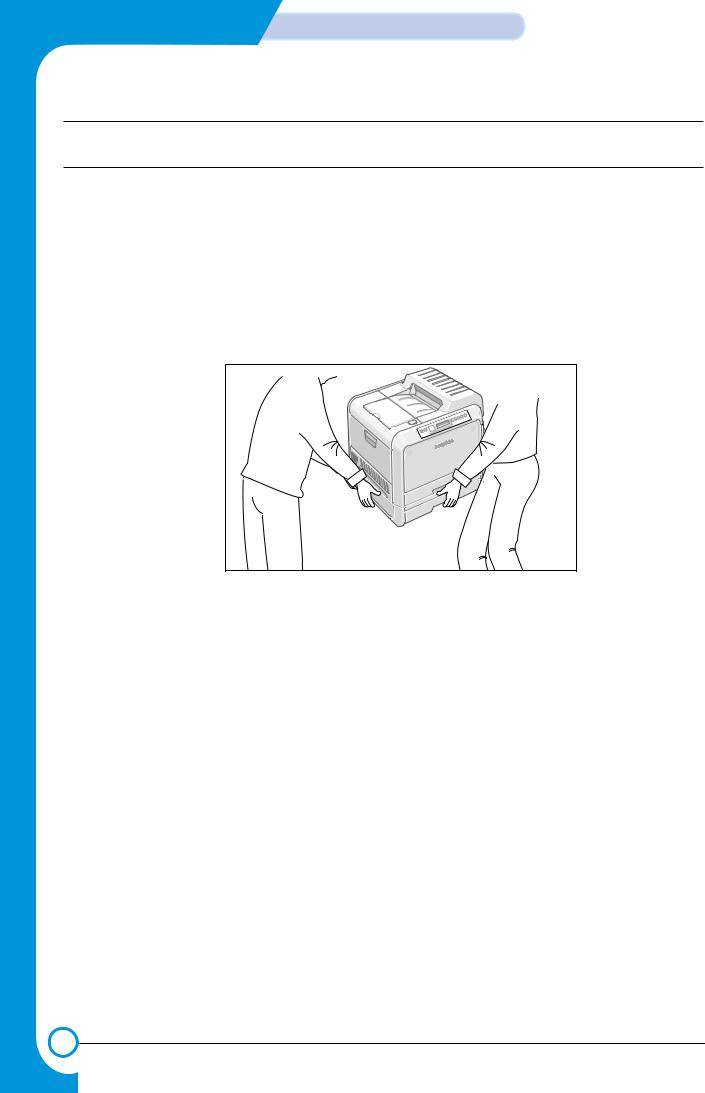
(3)When you move the printer.
This printer weighs 32kg including toner cartridge and cassette. Use safe lifting and handling techniques. Use the lifting handles located on each side of the machine. Back injury could be caused if you do not lift carefully.
(4)Ensure the printer is installed safely.
The printer weighs 32Kg, ensure the printer is installed on a level surface, capable of supporting its weight. Failure to do so could cause the printer to tip or fall possibly causing personal injury or damaging the printer.
(5)Do not install the printer on a sloping or unstable surface. After installation, double check that the printer is stable.
Service Manual

Precautions
1.3 ESD Precautions
Certain semiconductor devices can be easily damaged by static electricity. Such components are commonly called “Electrostatically Sensitive (ES) Devices”, or ESDs. Examples of typical ESDs are: integrated circuits, some field effect transistors, and semiconductor “chip” components.
The techniques outlined below should be followed to help reduce the incidence of component damage caused by static electricity.
Caution >>Be sure no power is applied to the chassis or circuit, and observe all other safety precautions.
1.Immediately before handling a semiconductor component or semiconductor-equipped assembly, drain off any electrostatic charge on your body by touching a known earth ground. Alternatively, employ a commercially available wrist strap device, which should be removed for your personal safety reasons prior to applying power to the unit under test.
2.After removing an electrical assembly equipped with ESDs, place the assembly on a conductive surface, such as aluminum or copper foil, or conductive foam, to prevent electrostatic charge buildup in the vicinity of the assembly.
3.Use only a grounded tip soldering iron to solder or desolder ESDs.
4.Use only an “anti-static” solder removal device. Some solder removal devices not classified as “anti-static” can generate electrical charges sufficient to damage ESDs.
5.Do not use Freon-propelled chemicals. When sprayed, these can generate electrical charges sufficient to damage ESDs.
6.Do not remove a replacement ESD from its protective packaging until immediately before installing it. Most replacement ESDs are packaged with all leads shorted together by conductive foam, aluminum foil, or a comparable conductive material.
7.Immediately before removing the protective shorting material from the leads of a replacement ESD, touch the protective material to the chassis or circuit assembly into which the device will be installed.
8.Maintain continuous electrical contact between the ESD and the assembly into which it will be installed, until completely plugged or soldered into the circuit.
9.Minimize bodily motions when handling unpackaged replacement ESDs. Normal motions, such as the brushing together of clothing fabric and lifting one’s foot from a carpeted floor, can generate static electricity sufficient to damage an ESD.
1.4 Super Capacitor or Lithium Battery Precautions
1.Exercise caution when replacing a super capacitor or Lithium battery. There could be a danger of explosion and subsequent operator injury and/or equipment damage if incorrectly installed.
2.Be sure to replace the battery with the same or equivalent type recommended by the manufacturers.
3.Super capacitor or Lithium batteries contain toxic substances and should not be opened, crushed, or burned for disposal.
4.Dispose of used batteries according to the manufacturer’s instructions.
Service Manual

Precautions
MEMO
Service Manual
Reference Information
22. Reference Information
This chapter contains the tools list, list of abbreviations used in this manual, and a guide to the location space required when installing the printer. A definition of tests pages and Wireless Network information definition is also included.
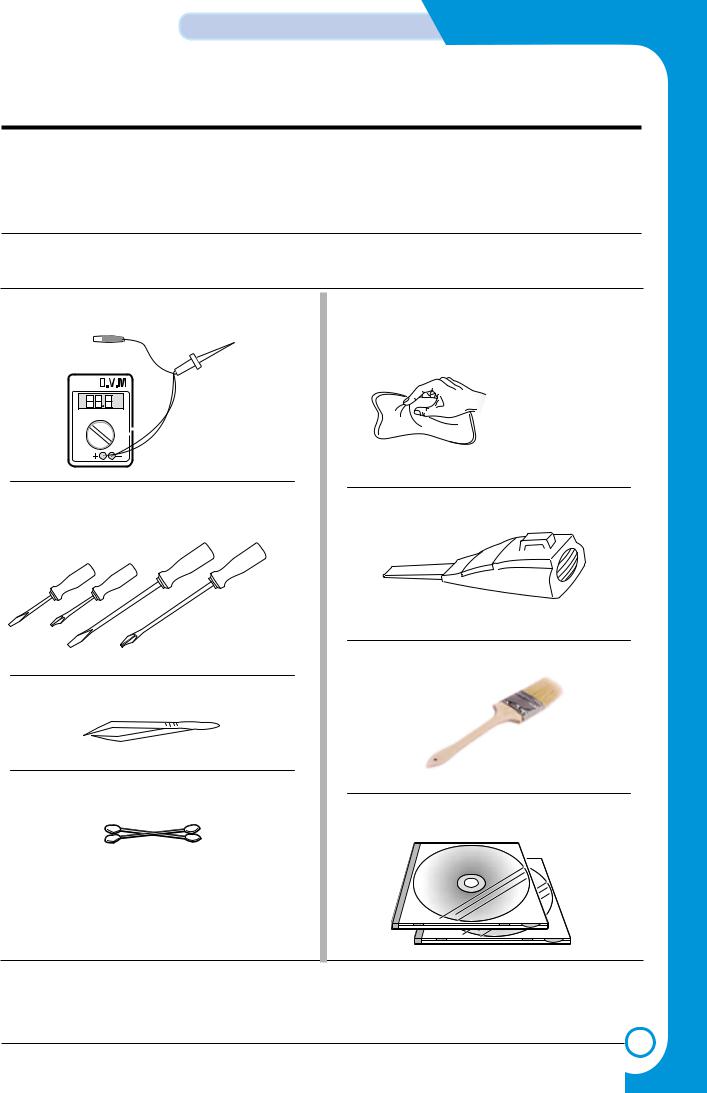
2.1 Tools for Troubleshooting
The following tools are recommended safe and easy troubleshooting as described in this service manual.
•DVM(Digital Volt Meter)
Standard : Indicates more than 3 digits.
•Driver
Standard : "-" type, "+" type (M3 long, M3 short, M2 long, M2 short).
•Tweezers
Standard : For general home use, small type.
•Cotton Swab
Standard : For general home use, for medical service.
•Cleaning Equipments
Standard : An IPA(Isopropyl Alcohol)dry wipe tissue or a gentle neutral detergent and lint-free cloth.
• Vacuum Cleaner
• Brush
• Software (Driver) installation CD ROM
Install Driver CD
Network S/W CD
Service Manual
Samsung Electronics

Reference Information
2.2 Acronyms and Abbreviations
The table below explains the abbreviations and acronyms used in this service manual. Where abbreviations or acronyms are used in the text please refer to this table.
ADC |
Analog-to-Digital-Conversion |
AP |
Access Point |
AC |
Alternating Current |
ASIC |
Application Specific Integrated |
Circuit |
|
ASSY |
Assembly |
BIOS |
Basic Input Output System |
BLDC Motor |
Brushless DC Motor |
CLBP |
Color Laser Beam Printer |
CMOS |
Complementary Metal Oxide |
|
Semiconductor |
CMYK |
Cyan, Magenta, Yellow, Black |
CN |
Connector |
CON |
Connector |
CPU |
Central Processing Unit |
CTD Sensor |
Color Toner Density Sensor |
dB |
Decibel |
dBA |
A-Weighted decibel |
dBm |
Decibel milliwatt |
DC |
Direct Current |
DCU |
Diagnostic Control Unit |
DIMM |
Dual In-line Memory Module |
DPI |
Dot Per Inch |
DRAM |
Dynamic Random Access Memory |
DVM |
Digital Voltmeter |
ECP |
Enhanced Capability Port |
ECU |
Engine Control Unit |
EEPROM |
Electronically Erasable |
|
Programmable Read Only Memory |
EMI |
Electro Magnetic Interference |
EP |
Electro photographic |
EPP |
Enhanced Parallel Port |
F/W |
Firmware |
FCF/FCT |
First Cassette Feeder/First |
|
Cassette Tray |
FISO |
Front-In, Side-Out |
FPOT |
First Print out Time |
GDI |
Windows Graphic Device Interface |
GIF |
Graphic Interchange Format |
GND |
Ground |
HBP |
Host Based Printing |
HDD |
Hard Disk Drive |
HTML |
Hyper Text Transfer Protocol |
HV |
High Voltage |
HVPS |
High Voltage Power Supply |
I/F |
Interface |
I/O |
Input and Output |
lb |
Pound(s) |
IC |
Integrated Circuit |
ICC |
International Color Consortium |
IDE |
Intelligent Drive Electronics or |
|
Integrated Drive Electronics |
IEEE |
Institute of Electrical and |
|
Electronics Engineers. Inc |
IOT |
Image Output Terminal (Color print- |
|
er, Copier) |
IPA |
Isopropy Alcohol |
IPC |
Inter Process CommunicationEPP |
|
Enhanced parallel Port |
IPM |
Images Per Minute |
ITB |
Image Transfer Belt |
LAN |
local area network |
LBP |
Laser Beam Printer |
Service Manual
Samsung Electronics
Reference Information
LCD |
Liquid Crystal Display |
LED |
Light Emitting Diode |
LSU |
Laser Scanning Unit |
MB |
Megabyte |
MHz |
Megahertz |
MPBF |
Mean Prints Between Failure |
MPF/MPT |
Multi Purpose Feeder/Multi |
|
Purpose Tray |
NIC |
Network Interface Card |
NPC |
Network Printer Card |
NVRAM |
Nonvolatile Random Access |
|
Memory |
OPC |
Organic Photo Conductor |
PBA |
Printed Board Assembly |
PCL |
Printer Command Language , |
|
Printer Control Language |
PCI |
Peripheral Component |
|
Interconnect by Intel 1992/6/22, is |
|
a local bus standard developed by |
|
Intel and introduced in April, 1993 : |
|
A60, B60 Pins |
PCL5Ce |
Printer Command Language 5Ce- |
|
Color |
PCL6 |
Printer Command Language 6 |
Portable Document Format |
|
PDL |
Page Description Language |
Ping |
Packet internet or Inter-Network |
|
Groper |
PPD |
Postscript Printer Discription |
PPM |
Page Per Minute |
PS |
Post Script |
PS3 |
Post Script Level3 |
PTL |
Pre-Transfer Lamp |
PWM |
Pulse Width Moduration |
Q’ty |
Quantity |
RAM |
Random Access Memory |
RCP |
Remote Control Panel |
ROM |
Read Only Memory |
SCF/SCT |
Second Cassette Feeder/Second |
|
Cassette Tray |
SMPS |
Switching Mode Power Supply |
SPGP |
Samsung Printer Graphic |
|
Processor |
SPL |
Samsung Printer Language |
SPL-C |
Samsung Printer Language-Color |
Spool |
Simultaneous Peripheral Operation |
|
Online |
SRS |
Software Requirment Specification |
SURF |
Surface Rapid Fusing |
SW |
Switch |
sync |
Synchronous or Synchronization |
T1 |
ITB |
T2 |
Transfer Roller |
TRC |
Toner Reproduction Curve |
PnP |
Universal Plug and Play |
U.I. |
User Interface |
URL |
Uniform Resource Locator |
USB |
Universal Serial Bus |
VCCI |
Voluntary Control Council for |
|
Interference Information |
|
Technology Equipment |
WECA |
Wireless Ethernet Compatibility |
Alliance |
|
Wi-Fi |
Wireless Fidelity |
Service Manual
Samsung Electronics
Reference Information
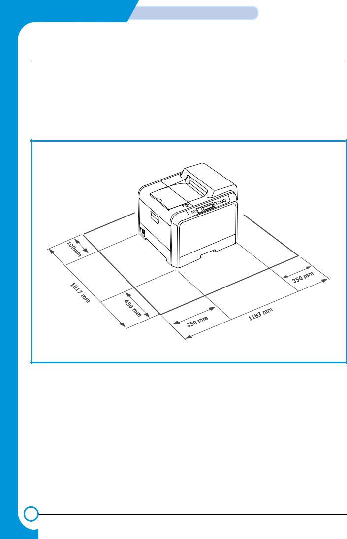
for the printer
trays, covers, and allow for proper ventilation. (see diagram
of air conditioners, heaters, or ventilators of temperature, sunlight, or humidity
Service Manual
Samsung Electronics

Reference Information
2.4 A4 ISO 19752 Standard Pattern
This test page is reproduced at 70% of the normal A4 size
Service Manual
Samsung Electronics

Reference Information
2.5 Wireless LAN
•This product can be used with a wireless LAN, (this is an option.)
-The wireless LAN function uses radio technology, instead of using LAN cable, to connect to an access point for printing.
-For a wireless LAN connection in Infrastructure mode an AP is needed, (purchased separately)
-For a wireless LAN connection in Ad-Hoc mode an appropriate Wireless I/F card is required fitted to a computer, (purchased separately)
-It is possible to use a wireless LAN connection with wired LAN.
-If an AP is installed in an office or at home, the wireless LAN function can be simply configured and used.
•Types of desk top PC (or Lap top) that uses the wireless LAN.
|
Division |
Basic type |
Recommend type |
|
|
CPU |
Over PENTIUM 233M |
PENTIUM 300MHz |
|
|
|
|
|
|
|
MEMORY |
Over 64MB |
Over 128MB |
|
|
|
|
|
|
|
VIDEO CARD |
Over 800X600 |
Over 1024X768 |
|
|
|
|
|
|
|
OS |
Over WINDOWS 98 |
Over WINDOWS ME |
|
|
|
|
|
|
|
INTERFACE CARD |
A product has a certificated mark of Wi-FiTM |
||
|
|
|
|
|
•About the certificated mark of Wi-FiTM
-Wi-FiTM is a registered trademark of the WECA (Wireless Ethernet Compatibility Alliance). Over 50 wireless LAN companies are member of
this organisation. Most of the main wireless networking companies are attending including such companies as Lucent Technologies, Cisco, Intel/Symbol, 3Com, Enterasys (Cabletron), Compaq, IBM, Nokia, Dell, Philips, Samsung Electronics, Sony, Intersil, etc.. This mark certifies mutual compatibility amongst the product of these companies. Wi-FiTM (IEEE 802.1) is certified as a standard of the wireless LAN market.
Service Manual
Samsung Electronics

Specifications
33. Specifications
Specifications are correct at the time of printing. Product specifications are subject to change without notice. See below for product specifications.
3.1 General Specifications
Items |
|
|
|
Descriptions |
Print Method |
Non-impact Electro-photography |
|
||
Developing system |
Non-Magnetic, Mono-Component Developing System |
|||
*Print Speed |
Mono |
|
Up to 24 PPM in A4, Up to 25 PPM in Letter size |
|
|
Color |
|
Up to 6 PPM in A4, Up to 6 PPM in Letter size |
|
|
|
|
||
Resolution |
Up to 1200 DPI effective output, True 600 X 600dpi |
|||
|
|
|
||
Source of Light |
Laser diode (LSU : Laser Scanning Unit) |
|||
|
|
|
|
|
Warm-Up Time |
More than 99 sec |
|
|
|
|
|
|
|
|
First Print Time |
Mono |
|
15 seconds (Ready to 1st page out) |
|
|
|
|
|
|
|
Color |
|
24 seconds (Ready to 1st page out) |
|
|
|
|
||
Feed Method |
Cassette , MPT(Multi Purpose Tray), SCT(Second Cassette Tray) |
|||
Media Size |
76 X 128mm (3 x 5”) to 216 X 356mm (8.5 X 14”) |
|||
Media Thickness |
Cassette : 16 ~24 lb , MPT : 16 ~ 43 lb |
|||
Dimension (W X D X H) |
510 X 470 X 405 mm |
|
|
|
|
|
|
|
|
Weight |
Net |
|
25.5 Kg |
56.2Lbs |
|
Gross |
|
32.0 Kg |
70.5Lbs |
|
|
|
|
|
**Acoustic Noise |
Stand by |
|
More than 40 dBA-TBD |
|
|
|
|
|
|
|
Printing |
|
More than |
48 dBA (Color)-TBD |
|
|
|
||
Power save mode |
Available, Setting : 5min/10min/15min/30min/45min/60min/120min |
|||
|
|
|
|
|
Toner save mode |
Disable |
|
|
|
Machine Life |
Mono : More than 300,000 pages, Color : More than 75,000 pages |
|||
|
|
|
|
|
*Print speed will be affected by Operating System used, computing performance, application software, connecting method, media type, media size and job complexity.
*OHP/Cardstock/Envelope : Half Speed
**Sound Pressure Level, ISO 7779
Service Manual
Samsung Electronics

Specifications
3.2 Controller Specification
Items |
|
Descriptions |
||
Processor (CPU) |
Samsung SPGPm (CLOCK SPEED 120Mhz), 32-bit RISC core (ARM 946ES) |
|||
|
|
|
|
|
Memory |
FLASH ROM (PROGRAM) : 8MB flash |
|||
|
|
|
|
|
|
|
*RAM : 64MB (Expandable to 320MB : With Option |
||
|
|
|
|
|
|
|
Option DIMM module : 64/128/256MB |
||
|
|
|
|
|
|
|
100Pin SDRAM DIMM (Samsung Printer Only) |
||
|
|
|
|
|
|
|
EEPROM (NVRAM) : 1024bytes |
|
|
Emulation |
SPL-Color |
|
|
|
Operating System |
Win 95/98/ME/NT4.0/2000/XP, Various Linux OS including Red Hat, Caldera, Debian, |
|||
|
|
Mandrake, Slackware, SuSE and Turbo Linux |
||
Interface |
Parallel : IEEE 1284 Bidirectional (Korea, Russia, Asia only) |
|||
|
|
- Modes supported : Compatible, Nibble, Byte, ECP |
||
|
|
|
|
|
|
|
USB (without HUB mode) |
|
|
|
|
- USB 2.0 compliant |
-12/480 Mbps 1 port |
|
|
|
|
|
|
|
|
Network Interface |
|
|
|
|
- 10/100 Base TX |
|
|
|
|
10/100 Base TX + 802.11b Wireless LAN |
||
|
|
|
|
|
Interface switching |
Automatic |
|
|
|
|
|
|
|
|
Interface time-out |
5min (Max.) |
|
|
|
|
|
|||
Font |
Windows font, PS english font, PCL english font |
|||
|
|
|
|
|
Color Management |
ICC ICM V3.4 |
|
|
|
|
|
|
|
|
*Memory Slots : Standard Capacity is 64MB Option Capacity is 320MB (Max) (100Pin 1 slot, 64MB/128MB/256MB)
3.3 Electrical Specification
Items |
|
Descriptions |
Remarks |
|
Input Voltage |
Nominal input voltage |
|
200-240 VAC / 100~127VAC |
|
|
|
|
|
|
|
Input voltage range |
|
180-264 VAC/ 90~132VAC |
|
|
|
|
|
|
|
Nominal frequency |
|
50/60 MHz |
|
|
|
|
|
|
|
Frequency tolerance |
|
+3Hz |
|
|
|
|
|
|
Power Consumption |
Printing :450W max (with SCF) |
|
||
|
|
|
|
|
|
Power Save : 35W max |
|
|
|
|
|
|
|
|
3.4 Environmental Range
Items |
|
Operating |
Storage |
|
Temperature |
15~32.5 ˚C(50-90 ˚F) |
|
-20~40 ˚C (-4~104 ˚F) |
|
|
|
|
|
|
Humidity |
20~80%RH |
|
10~80%RH |
|
|
|
|
|
|
Service Manual
Samsung Electronics

Specifications
3.5 Consumable & Maintenance Items
Items |
|
Descriptions |
|
Remarks |
||
Periodic Replacing Parts |
Toner Cartridge(Black) |
initial (3,000 pages@5% coverage) |
|
User replace |
||
|
|
|
|
|
|
|
|
|
|
replacement (7,000 pages@5% coverage) |
|
|
|
|
|
|
|
|
|
|
|
|
Toner Cartridge(Cyan) |
initial (2,000 pages@5% coverage) |
|
User replace |
|
|
|
|
|
|
|
|
|
|
|
replacement (5,000 pages@5% coverage) |
|
|
|
|
|
|
|
|
|
|
|
|
Toner Cartridge(Magenta) |
initial (2,000 pages@5% coverage) |
|
User replace |
|
|
|
|
|
|
|
|
|
|
|
replacement (5,000 pages@5% coverage) |
|
|
|
|
|
Toner Cartridge(Yellow) |
initial (2,000 pages@5% coverage) |
|
User replace |
|
|
|
|
|
|
|
|
|
|
|
replacement (5,000 pages@5% coverage) |
|
|
|
|
|
|
|
|
|
|
|
|
OPC Unit |
mono : 50,000 pages |
|
User replace |
|
|
|
|
|
|
|
|
|
|
|
color : 12,500 pages |
|
|
|
|
|
ITB Unit(T1 Roller) |
mono : 50,000 pages |
|
User replace |
|
|
|
|
|
|
|
|
|
|
|
color : 12,500 pages |
|
|
|
|
|
|
|
|
|
|
|
|
Waste Toner Tank |
3,000 images |
|
User replace |
|
|
|
|
|
|
|
|
|
|
Fuser Unit |
simplex : 100,000 page (Mono) |
|
Engineer |
|
|
|
|
duplex : 50,000 page |
|
|
|
|
|
Transfer Roller(T2 Roller) |
simplex : 50,000 page |
|
Engineer |
|
|
|
|
|
|
|
|
|
|
|
duplex : 25,000 page |
|
|
|
Option |
SCT |
- Paper capacity : 500sheets |
|
|||
|
|
|
|
|
|
|
|
|
(Second Cassette Tray) |
- Paper weight : 60 ~ 90 g/m2 / 16 ~ 24 lbs |
|
||
|
|
|
|
|
|
|
|
|
Network Printing |
- Ethernet 10/100baseTX + Wireless |
|
||
|
|
|
|
|
||
|
|
|
- Protocols : TCP/IP, SPX/IPX, Ethertalk, SNMP, HTTP |
|||
|
|
|
1.1, DLC/LLC |
|
||
|
|
|
|
|
||
|
|
|
- 8MB RAM Buffer for faster graphics performance |
|||
|
|
|
- 4MB Flash Memory for upgrade |
|
||
|
|
|
|
|
|
|
|
|
802.11b Wireless LAN |
- IEEE802.3b support |
|
||
|
|
|
|
|
|
|
|
|
|
- speed : 11, 5.5, 2 ,1Mbps |
|
||
|
|
|
|
|
|
|
|
|
|
- WEP : 64bit, 128bit |
|
||
|
|
|
|
|
||
|
|
|
- Operating range : 30m(Indoors) , 100m(Outdoors) |
|||
|
|
|
|
|
||
|
|
SDRAM DIMM |
- 64,128MB, 256MB 100Pin SDRAM DIMM(Use Samsung |
|||
|
|
|
Part Only) |
|
||
|
|
|
|
|
|
|
Service Manual
Samsung Electronics

Specifications
3.6 Paper handling Specifications
3.6.1 input Paper Size
Paper |
|
Paper size |
1st Cassette |
2nd Cassette |
MP tray |
Duplex |
|
A4 |
210 X 297 mm |
O |
O |
O |
O |
||
|
|
|
|
|
|
|
|
Letter |
216 X 279 |
(8.5 X 11") |
O |
O |
O |
O |
|
|
|
|
|
|
|
|
|
Folio (Legal13") |
216 |
X 330 |
(8.5 X 13") |
|
|
O |
O |
|
|
|
|
|
|
|
|
Legal (Legal14") |
216 |
X 356 |
(8.5 X14") |
|
|
O |
O |
Executive |
184 |
X 267 |
(7.25 X10.5") |
|
|
O |
|
Statement |
140 |
X 216(5.5 x8.5") |
|
|
O |
|
|
|
|
|
|
|
|
|
|
ISO B5 |
176 X 250 |
|
|
|
O |
|
|
JIS B5 |
182 X257 |
|
|
|
O |
|
|
A5 |
148.5 X 210 |
|
|
O |
|
||
|
|
|
|
|
|
||
A6 |
105 X148.5 |
|
|
O |
|
||
|
|
|
|
|
|
|
|
Com-10 Envelope |
105 X 241 |
(4.15 X 9.5") |
|
|
O |
|
|
|
|
|
|
|
|
||
Monarch Envelope |
98 X191 (3.87 X 7.5") |
|
|
O |
|
||
DL Envelope |
110 X 220(4.33 X 8.66") |
|
|
O |
|
||
|
|
|
|
|
|
|
|
C5 Envelope |
162 X 229 |
(6.38 X 9.01") |
|
|
O |
|
|
|
|
|
|
|
|
||
C6 Envelope |
114 X 162 (4.49 X 6.38") |
|
|
O |
|
||
|
|
|
|
|
|
||
Transparency (OHP) |
A4 or Letter |
|
|
O |
|
||
|
|
|
|
|
|
||
Label paper |
A4 or Letter |
|
|
O |
|
||
|
|
|
|
|
|
|
|
O : Supported
3.6.2 Input Capacity
Items |
|
Descriptions |
Remarks |
|
Cassette(FCT) |
250 sheets |
|
|
|
|
|
|
|
|
MP tray |
Paper |
|
100 sheets |
|
|
|
|
|
|
|
Transparencies |
|
30 sheets |
|
|
|
|
|
|
|
Envelopes |
|
10 sheets |
|
|
|
|
|
|
|
Labels |
|
10 sheets |
|
|
|
|
|
|
Option Cassette(SCT) |
500 sheets |
|
|
|
|
|
|
|
|
3.6.3 Output Capacity
Items |
Descriptions |
Remarks |
Face Down |
250 sheets |
|
|
|
|
Service Manual
Samsung Electronics
Summary of product
44. Summary of Product
This chapter describes the functions and operating principles of the main components.
4.1 System Structure
4.1.1 Main Parts of System
|
|
|
|
Deve Cover |
|
HVPS |
|
|||
SCT |
ASSEFCT |
|
LSU |
Cyan- .DEV |
Magenta- .DEV |
Yellow- .DEV |
Black- .DEV |
|
|
|
SCF |
|
|
|
|
|
|
|
|
|
|
SCF |
|
|
|
|
|
|
|
PTLPTL |
|
|
Path |
|
|
|
|
|
OPC |
|
Unit ITB |
|
UnitUnitEXITEXIT |
up-Pick Roller |
Roller |
up-Pick |
|
Lamp Eraser |
|
|
|
Unit Fuser |
||
Feeder |
|
DUPLEX |
Roller T2 |
|||||||
|
|
Roller |
up-Pick |
|
|
|
|
|
|
|
MPTF |
|
PathMPF |
|
|
|
|
|
|
|
|
Service Manual
Samsung Electronics
Summary of Product
>> Front View
Panel PBA
Deve OEM
PBA
Waster Toner Sensor
Waster Toner Motor
>> Rear View
Deve Drive
Deve Drive PBA
Fan
|
Main Drive |
Deve Cover |
|
|
Open S/W |
Duplex Cover |
SMPS |
|
Open S/W |
|
|
|
|
Main Conrtoller PBA
Service Manual
Samsung Electronics
Summary of product
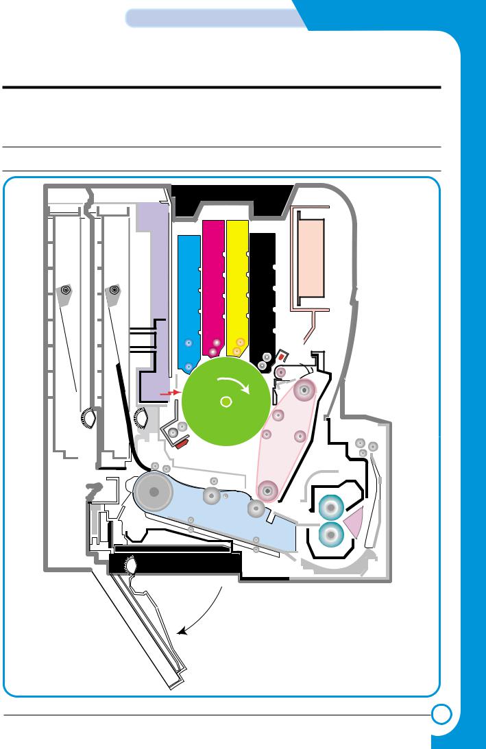
1) OPC Unit
Images are created on the OPC unit using an electro-photographic process. The unit consists of:-
* OPC Drum |
|
* Waste Toner Ass'y |
used to collect waste toner remaining on the OPC drum, |
* Charge Roller Assy |
|
2) ITB Unit |
|
ITB stands for Image Transfer Belt. An image developed on the OPC Drum is transferred first to the ITB. This is called the T1 Transfer (Primary Image Transfer).
Images are built up in layers on the ITB.
First the Yellow (Y) colour image is created on the OPC and transferred to the ITB Next the Magenta (M) colour image is created on the OPC and transferred to the ITB Followed by the Cyan (C) and Black (K) images.
3) Transfer Roller
Once the complete, full colour, image, has been built up on the ITB the Transfer Roller is used to transfer the image onto paper. This is called the T2 Transfer (Secondary Image Transfer)
4) FCT (First Cassette Tray)
It stores and automatically feeds print paper.
Pick-up Roller picks up paper, controls drive, feeds paper, removes static electricity, and so on.
> Spec.
*Paper arrange way : Side Registration
*Paper Direction : FISO (Front-in, Side-Out)
*Cassette Type : A4, Ltr
*Paper Discharge : Separation Claw
*Capacity : 250 Sheets (Standard paper 75mg/m? 20lb)
*Paper Size : A4, Letter
*Paper Weight (average) : 60~90g/m2 (16~24lbs)
*Paper Type : General Printing Paper
*Additional Function : Paper Empty Sensor
5)SCT (Second Cassette Tray)
This additionally stores and automatically feeds printing paper. Its function is the same as the FCT (First Cassette Tray)
> Spec.
*Paper arrangement : Side Registration
*Paper Direction : FISO (Front-in, Side-Out)
*Cassette Type : A4, Ltr
*Paper Discharge : Separation Claw
*Capacity : 500 Sheets (Standard paper 75mg/m2 20lb)
*Paper Size : A4, Letter
*Paper Weight (average) : 60~90g/m2 (16~24lbs)
*Paper Type : General Printing Paper
*Additional Function : Paper Empty Sensor
Service Manual
Samsung Electronics

Summary of Product
6) MPT (Multi Purpose Tray)
The Multi-Purpose Tray not only feeds general printing paper but is also used for many other kinds of paper such as those paper sizes not supported by the cassette, envelopes, OHP, etc.
> Spec.
*Capacity : Cut Sheet : 100 Sheets (Standard paper 75mg/m2 20lb)
*OHP : 300 Sheets
*Envelope & Label & Card Stock : 10 Sheets
*Paper Arrangement : Side Registration
*Power : Main Motor (BLDC)
*Driving Management : Solenoid
*Paper Discharge : Friction Pad Method
*Paper Size : Legal, Folio, A4, Letter, Executive, JIS B5, A5, A6
*Paper Weight (Average) : 60~163g/m2
*Paper Type : General, Label, Post Card, Transparency, Envelope, Card Stock (Tracing
Paper is not served)
* Additional Function : Paper Empty Sensor
7) Feeder
* Paper Arrangement : Side Registration.
* Power : Main Motor (BLDC)
* Paper Management : Solenoid
8) Duplex Unit
The Duplex Unit is used to reverse feed paper when printing on the second side (known as Double sided or Duplex printing). The Duplex Unit is not an optional extra, it is built-in at manufacturing time and is integral with the Transfer Roller.
> Spec.
* Power : Main Motor (BLDC)
* Paper Reverse Function: After the front side of the original document is printed, it is transferred to the duplex unit in order to print the reverse side of original document. The motor drives the exit roller in the reverse direction to feed the paper back into the machine.
9) Exit Unit
The Exit Unit guides paper that is just about to leave the print engine. Printed-paper is discharged by the Exit Roller and Kicker into the Output Tray.
> Spec.
*Capacity : 250 sheets (Standard A4, 75g/m2)
*Paper Direction : Face Down
*Exit Drive Roller : It is driven by Main Motor (BLDC), and it rotates clockwise for normal feed and antic-clockwise when reverse feeding for duplex printing.
*Bin Full Sensor : There is no Bin Full sensor fitted on this model.
10)Toner Cartridge
There are four toner cartridges, each containing a different colour ink : C (Cyan), M (Magenta), Y (Yellow) , and K (Black).
Each one of these toner cartridge is independent and can be changed independently.
11) Fuser Unit
This unit consists of 2 Heat Lamps, 2 Heat Rollers, 2 Thermostats and a Thermister. It melts and fuses the toner, transferred by the transfer roller onto the paper, by applying pressure and high temperature to complete printing job.
12) LSU
This is a core part of LBP. It forms a latent image on the surface of OPC drum using a static charge.
* Resolution: Real 600 dpi
Service Manual
Samsung Electronics

Summary of product
13) Main Drive Unit
This motor drives, by way of a gearbox, the OPC unit, ITB unit, feeder unit, fuser unit, exit unit and duplex unit.
> Spec.
*Power : 20W Max (24V)
*Drives : OPC unit, ITB unit, Fuser, Feeder, Duplex unit, Exit unit
14)DEVE Drive Unit
This motor drives, by way of a gearbox, the toner cartridges and ITB cleaning cam.
> Spec.
*Power : 20W Max (24V)
*Drives : DEV (4 Color)/ITB Cleaning)
15)SMPS (Switching Mode Power Supply)
This power supply uses the AC supply voltage to generate the DC voltages used by the system. The SMPS has 4 output channels (+3.3V, +5V, +24V, +24VF).
The AC Heater Control Unit that supplies power to the fuser is also located on the SMPS.
16) HVPS (High Voltage Power Supply)
The HVPS creates the high voltages (Charger, Supply, T1, T2, Developer) used for the electro photographic process. The high voltage is created from the 24V line from the SMPS. High Voltage output is supplied to the toner cartridge, OPC drum unit, ITB unit, and Transfer roller.
17) Main Controller PBA
The Main controller PBA is very important as it is the heart of printer. It has several major function blocks.
*CPU and SPGPm Block: This manages the printing order from the host, creates bitmap data for the engine to print and controls various devices that are needed to operate the printer.
*Engine Control Block: This manages images and controls various kinds of I/O
*Memory Block : The operating system uses this to store video data and printing orders given by host.
*ROM Block : The printer OS and PDL Interpreter are stored here.
*In addition there are USB 2.0 Block, IEEE 1284 Block, Option Block, OPE Panel, etc.
18)DEVE Drive PBA
Each toner cartridge requires the HV Supply only when that colour image is being processed. This unit takes its HV source from the HVPS and using 4 solenoids selects which cartridge is to receive the Supply voltage. This section also contains the DEVE motor, DEVE clutch, and DEVE solenoid drives. These are activated in sequence as required by the printing process.
19) DEVE OEM PBA
This detects new or used toner cartridges and also checks that cartridges are approved parts. If a toner cartridge is not suitable for the machine an error message is displayed.
20) Waste Toner Ass’y
A cleaner blade on the OPC unit cleans waste toner from the OPC drum after every image is transferred to the ITB. Once the complete image is transferred from the ITB onto paper the ITB Cleaning Solenoid activates and a cleaning blade removes waste toner from the ITB. Waste toner is transferred to the waste toner tank.
The error message "Waste Toner Tank Full/ Not Install" is indicated on the LCD Panel. Replace the Waste Toner Tank immediately or the printer may be damaged
Service Manual
Samsung Electronics
Summary of Product
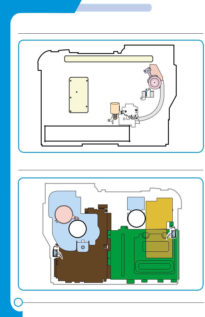
4.1.2 Motor & Fan Layout
1. Main Motor
2. DEVE Motor
Fan
4. Waste Toner Motor
NO. |
Name |
Description |
1 |
Main Motor |
Drives the OPC unit, ITB unit, feeder unit, fuser unit, exit unit and |
|
|
duplex unit. |
|
|
|
2. |
DEVE Motor |
Drives C, M, Y and K toner cartridges and ITB cleaning cam. |
|
|
|
3. |
Fan |
Forces cold air into the printer and takes out heat from the fuser. |
|
|
|
4. |
Waste Toner Motor |
Transfers collected waste toner from the OPC drum and ITB to the |
|
|
waste toner tank. (Refer to front view picture on 4-2 page) |
|
|
|
Service Manual
Samsung Electronics
Summary of product
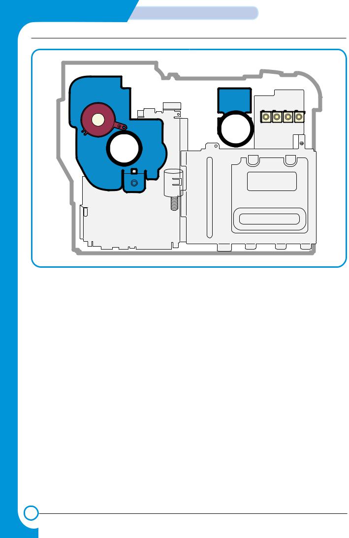
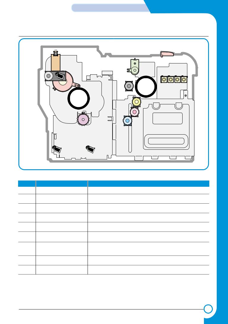
14.1.3 Clutch & Solenoid Layout
 Duplex Solenoid
T2 Home Solenoid
ITB Cleaning
Solenoid
Cartridge Solenoid(C, K,M, Y,, M)K)
Black Deve
Clutch
Yellow Deve Clutch
Magenta Deve Clutch |
Cyan Deve Clutch |
Feed Regi
Clutch
|
MP Pick_up |
Pick_up Solenoid |
|
Solenoid |
|
>>Solenoid |
|
|
NO. |
Name |
Description |
1. |
C DEVE solenoid |
Controls the High Voltage supply to the cyan cartridge. |
2. |
K DEVE solenoid |
Controls the High Voltage supply to the black cartridge. |
3. |
Y DEVE solenoid |
Controls the High Voltage supply to the yellow cartridge.. |
4. |
M DEVE solenoid |
Controls the High Voltage supply to the magenta cartridge. |
5. |
Pick-up solenoid |
Controls the pick-up roller drive. |
6. |
MP Pick-up solenoid |
Controls the MP pick-up roller drive. |
7. |
Duplex solenoid |
When operating in duplex print mode, this reverses the direction |
|
|
of paper feeding to feed paper into the duplex unit. |
8. |
T2 Home solenoid |
This forces the transfer roller into contact with the ITB unit. |
9. |
ITB cleaning solenoid |
This brings the cleaning blade into contact with the ITB unit |
Service Manual
Samsung Electronics

Summary of Product
>>Clutch
NO. |
Name |
Description |
1. |
Yellow DEVE clutch |
Controls Yellow color toner cartridge drive |
|
|
|
2. |
Magenta DEVE clutch |
Controls Magenta color toner cartridge drive |
|
|
|
3. |
Cyan DEVE clutch |
Controls Cyan color toner cartridge drive |
|
|
|
4. |
Black DEVE clutch |
Controls Black color toner cartridge drive |
|
|
|
5. |
Feed Regi. Clutch |
Controls the location of picked-up paper |
|
|
|
4.1.4 Sensor & Micro S/W Layout
NO. |
Name |
Description |
1. |
Paper Empty Sensor(FCT) |
This sensor detects paper in the first (main) cassette. |
|
|
|
2. |
Paper Empty Sensor(SCT) |
This sensor detects paper in the second (optional) cassette. |
|
|
|
3. |
Paper Empty Sensor(MPT) |
This sensor detects paper in the multi-purpose tray. |
|
|
|
4. |
Feed Sensor |
This sensor must operate within a certain time after paper pick- |
|
|
up otherwise a JAM is detected |
|
|
|
5. |
ITB Home Sensor |
This detects the position of the image transfer belt, and in |
|
|
dicates the start location for image writing. It is used to ensure |
|
|
that all 4 colour images are correctly registered. |
|
|
|
6. |
Waste Toner Sensor |
This detects whether the waste toner tank is mounted or not and |
|
|
the amount of waste toner in the tank. |
|
|
|
7. |
Exit Sensor |
This detects whether printing paper is discharged or not. |
|
|
|
8. |
DEVE Cover Open S/W |
This detects the open/closed status of the DEVE Cover. |
|
|
|
9. |
Duplex Cover Open S/W |
This detects the open/closed status of the Duplex Cover. |
|
|
|
Note: * ITB Home Sensor is located in the ITB unit. If it develops a fault replace the ITB unit.
*Please, refer to the Chap. 7 Arrangement and Adjustment, "Paper Path diagram", for the location of the paper empty sensor, feed sensor, and exit sensor.
*Please, refer to page 4-2 for the location of the waste toner sensor, DEVE cover open S/W, and duplex cover open S/W.
Service Manual
Samsung Electronics
Summary of product
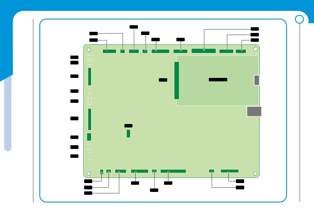
4.1.5 Main Controller PBA
TH3 CN15
WASTE TONER & EXIT CN17
DUPLEX CN24

T2 HOME CN26

BLDC1 CN27
TH1 CN28

FUSER_FAN CN29
SMPS CN30
MP_EMPT CN31
MP SOL CN32

FEED CN33

PICK_UP CN25
CLT_FEED CN23
EMPT CN21
CN11 PTL & TH4 |
|
CN7 |
HVPS |
|
|
||
CN35 SOL_ITB_CLN |
|
CN37 |
OEM_CONN |
|
|
||
CN38 BLDC2 |
CN10 ITB |
CN4 |
PANEL |
CN9 NIC |
Option : NIC |
LAN |
USB |
CN1 For Test
CN16 SCF |
CN12 |
CN5 |
DEVE_DRIVER |
LSU |
|
||
CN6 |
OPC KEY |
CN14 |
LSU SW |
|
|
Service Manual
Samsung Electronics
Summary of Product
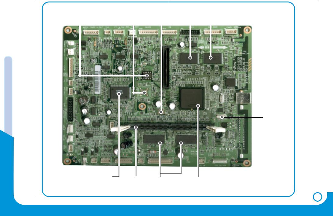
U36 |
OSC3 |
|
||
(Counter Memory) |
23.8807368MHz |
|
||
|
|
|
|
|
|
|
|
|
|
LPEC1 |
DIMM |
|
(ENGINE CONTROL) |
||
|
OSC2 12MHz |
FLASH MEMORY |
|||
(Reserved) |
||||
|
|
|||
|
|
|||
|
|
|
|
|
|
|
|
|
|
|
|
|
|
|
|
|
|
|
|
OSC1
12MHz
RAM |
SPGPm |
|
Main Control |
Service Manual
Samsung Electronics
Summary of product
|
|
|
|
|
|
|
|
|
|
|
|
|
|
|
|
|
|
|
|
|
|
|
|
|
|
|
|
|
|
|
|
|
|
|
|
|
|
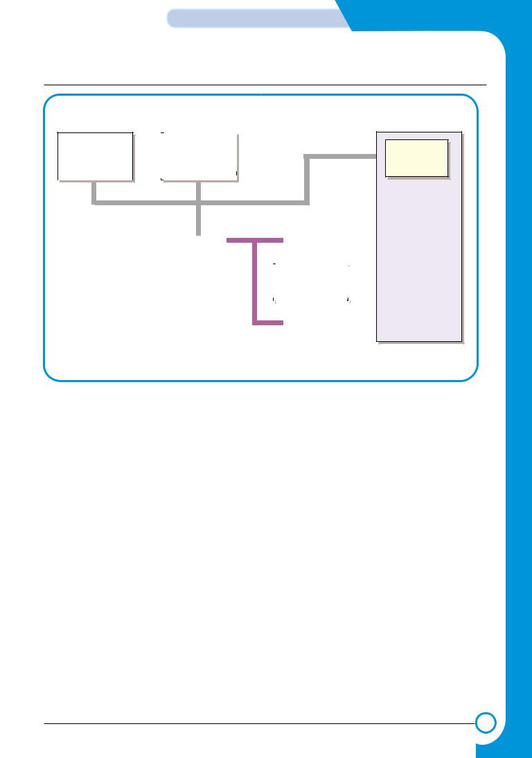
Flash Memory |
|
NPC / (W-LAN) |
|
|
|
|
|
|
|
||||||||||||||||||||||||||||
|
|
|
|
|
|
|
|
Optional |
|
|
|
|
|
|
LPEC1 |
||||||||||||||||||||||
2MB |
|
|
|
|
|
|
|
|
|
|
|
|
|
|
|||||||||||||||||||||||
|
|
|
|
Full Function |
|
|
|
|
|
|
|
||||||||||||||||||||||||||
|
|
|
|
|
|
|
|
|
|
|
|
||||||||||||||||||||||||||
|
|
|
|
|
|
|
|||||||||||||||||||||||||||||||
|
|
|
|
|
|
|
|
|
|
|
|
|
|
|
|
|
|
|
|
|
|
|
|
|
|
|
|
|
|
|
|
|
|
|
|
|
|
|
|
|
|
|
|
|
|
|
|
|
|
|
|
|
|
|
|
|
|
|
|
|
|
|
|
|
|
|
|
|
|
|
|
|
|
|
|
|
|
Engine |
|
|
|
|
|
|
|
|
|
|
|
|
|
|
|
|
|
|
|
|
|
|
|
|
|
|
|
|
|
|
|
|
|
|
|
|
|
|
|
|
|
|
|
|
|
|
|
|
|
|
|
|
|
|
|
|
|
|
|
|
|
|
|
|
|
|
|
|
|
|
|
|
|
|
|
|
|
|
|
|
|
|
|
|
|
|
|
|
|
|
|
|
|
|
|
|
|
|
|
|
|
|
|
|
|
|
|
|
|
|
|
|
|
|
|
|
|
|
|
|
|
|
|
|
|
|
|
|
|
|
|
|
|
|
|
|
|
|
|
|
|
|
|
|
|
|
|
|
|
|
|
|
|
|
|
|
|
|
|
|
|
|
|
|
|
|
|
|
|
|
|
|
|
|
|
|
|
|
|
|
|
|
|
|
|
|
|
|
|
|
|
|
|
|
|
|
|
|
|
|
|
|
|
|
|
|
|
|
|
|
|
|
|
|
|
|
|
|
|
|
|
|
|
|
|
|
|
|
|
|
|
|
|
|
|
|
|
|
|
|
|
|
|
|
|
|
|
|
|
|
|
|
|
|
|
|
|
|
|
|
|
|
|
|
|
|
|
|
|
|
|
|
|
|
|
|
|
|
|
|
|
|
|
|
|
|
|
|
|
|
|
|
SDRAM |
|||||||||||||||||||||||
|
|
|
|
|
|
|
|
|
|
|
|
|
|
|
|
|
|
|
|
|
|
|
|
|
|
|
|
|
|
|
|
|
|
|
|
|
|
|
|
|
|
|
|
|
|
|
|
|
|
|
|
|
|
|
Control |
|||||||||||||||||||||||
|
|
|
|
|
|
|
|
|
|
|
SPGPm |
|
|
|
|
|
|
|
64MB |
|||||||||||||||||||||||||||||||||||||||||||||||||||||||||||
|
|
|
|
|
|
|
|
|
|
|
|
|
|
|
|
|
|
Block |
||||||||||||||||||||||||||||||||||||||||||||||||||||||||||||
|
|
|
|
|
|
|
|
|
|
|
|
|
|
|
|
|
|
|
|
|
|
|
|
|
|
|
|
|
|
|
|
|
|
|
|
|
|
|
|
|
|
|
|
|
|
|
|
|
|
|
|
|
|
|
|
|
|
|
|
|
|
|
|
|
|
|
|
|
|
|
|
|
|
|
|
|
|
|
|
|
|
|
|
|
|
|
|
|
|
|
|
|
|
|
|
|
|
|
|
|
|
|
|
|
|
|
|
|
|
|
|
|
|
|
|
|
|
|
|
|
|
|
|
|
|
|
|
|
|
|
|
|
|
|
|
|
|
|
|
|
|
|
|
|
|
|
|
|
|
|
|
|
|
|
|
|
|
|
|
|
|
|
|
|
|
|
|
|
|
|
|
|
|
|
|
|
|
|
|
|
|
|
|
|
|
|
|
|
|
|
|
|
|
|
|
|
|
|
|
|
|
|
|
|
|
|
|
|
|
|
|
|
|
|
|
|
|
|
|
|
|
|
|
|
|
|
|
|
|
|
|
|
|
|
|
|
|
|
|
|
|
|
|
|
|
|
|
|
|
|
|
|
|
|
|
|
|
|
|
|
|
|
|
|
|
|
|
|
|
|
|
|
|
|
|
|
|
|
|
|
|
|
|
|
|
|
|
|
|
|
|
SDRAM DIMM |
|
||||||||||||||||||||||
|
|
|
|
|
5 pin UART |
|
|
|
|
|
|
|
|
|
|
|
|
|
|
|
|
|
|
|
|
|
|
|
|
|
|
|
|
|
|
|
|
|
|
|
|
|
|
|
|
|
|
|
|
|
34MB~128MB |
|
||||||||||||||||||||||||||
|
|
|
|
|
|
|
|
|
|
|
|
|
|
|
|
|
|
|
|
|
|
|
|
|
|
|
|
|
|
|
|
|
|
|
|
|
|
|
|
|
|
|
|
|
|
|
|
|
|
|
|
|
|
|
|
|
|
|
|
|
|
|
|
|
|
|
|
|
|
|
|
|
|
|||||
|
|
|
|
|
|
|
|
|
|
|
|
|
|
|
|
|
|
|
|
|
|
|
|
|
|
|
|
|
|
|
|
|
|
|
|
|
|
|
|
|
|
|
|
|
|
|
|
|
|
|
|
|
|
|
|
|
|
|
|
|
|
|
|
|
|
|
|
|
||||||||||
|
|
|
|
|
|
|
|
|
|
|
|
|
|
|
|
|
|
|
|
|
|
|
|
|
|
|
|
|
|
|
|
|
|
|
|
|
|
|
|
|
|
|
|
|
|
|
|
|
|
|
|
|
|
|
|
|
|
|
|
|
|
|
|
|
|
|
|
|
|
|
|
|
|
|
|
|
|
|
|
|
|
|
|
|
|
|
|
Panel |
|
|
|
|
|
|
|
EEPROM |
|
|
|
|
|
|
|
|
|
|
|
|
|
|
|
|
|
|
|
|
|
|
|
|
|
|
|
|
|
|
|
||||||||||||||||||||||||||||||
|
|
|
|
|
|
|
|
USB 2.0 |
|
|||||||||||||||||||||||||||||||||||||||||||||||||||||||||||||||||||||
|
|
|
|
|
|
|
|
16x2 LCD |
|
|
|
|
|
|
|
|
|
|
|
4k bit |
|
|
|
|
|
|
|
|
||||||||||||||||||||||||||||||||||||||||||||||||||
|
|
|
|
|
|
|
|
|
|
|
|
|
|
|
|
|
|
|
|
|
|
|
|
|
|
|
||||||||||||||||||||||||||||||||||||||||||||||||||||
|
|
|
|
|
|
|
|
|
|
|
|
|
|
|
|
|
|
|
|
|
|
|
|
|
|
|
|
|
|
|
|
|
|
|
|
|
|
|
|
|
|
|
|
|
|
|
|
|
|
|
|
|
|
|
|
|
|
|
|
|
|
|
|
|
|
|
|
|
|
|
|
|
|
|
|
|
|
|
|
|
|
|
|
|
|
|
|
|
|
|
|
|
|
|
|
|
|
|
|
|
|
|
|
|
|
|
|
|
|
|
|
|
|
|
|
|
|
|
|
|
|
|
|
|
|
|
|
|
|
|
|
|
|
|
|
|
|
|
|
|
|
|
|
|
|
|
|
|
|
|
|
|
|
|
|
|
|
|
|
|
|
|
|
|
|
|
|
|
|
|
|
|
|
|
|
|
|
|
|
|
|
|
|
|
|
|
|
|
|
|
|
|
|
|
|
|
|
|
|
|
|
|
|
|
|
|
|
|
|
|
|
|
|
|
|
|
|
|
|
|
|
|
|
|
|
|
|
|
|
|
|
|
|
|
|
|
1) CPU BLOCK
This is the heart of the machine. A 120MHz - 32bit RISC processor is used to manage commands and data supplied by the host. This is converted into a bitmap image which is passed to the engine block for printing. The CPU is also used to control various other devices e.g. the USB 2.0 Interface chip.
2) SPGPm overview
*Package
-272 pins PBGA
*Power
-1.8V(Core), 3.3V(IO) power operation
-P1284 inputs : 5V tolerant
*Speed
-120MHz core(ARM946ES) operation, 60MHz bus operation
-Supportable Engine Speed : under 30ppm
*Dual bus architecture for bus traffic distribution
-AMBA High performance Bus (AHB)
-System Bus with SDRAM
*Integrated ARM946ES
-32-bit RISC embedded processor core
-16KB instruction cache and 16KB data cache
-No Tightly Coupled Memory
-Memory Protection Unit & CP15 control program
Service Manual
Samsung Electronics

Summary of Product
*Direct connection up to 4 Flash ROM banks
-Burst capability
-Programmable timing per bank
-Up to 16MB address per bank (Limited to 8MB per bank when nDREQ0 is enabled)
*Direct connection up to 6 I/O banks & 4 DMA I/O banks
-Programmable timing per bank
-Programmable recovery timing per bank for slow devices
-Up to 16MB address per bank (Limited to 8MB per bank when nDREQ0 is enabled)
*Direct connection up to 5 SDRAM arrays
-SDRAM controller supports PC-66, PC-100 and PC-133 SDRAMs running at 60MHz
-Up to 128MB per array, up to 512MB totally
-Wide support of various SDRAM configurations, including programmable band and column address
-Programmable SDRAM refresh time interval
*4 General Purpose DMA controllers
-Extensible architecture allows peripheral devices such as scan devices to have access to SDRAM arrays through DMA channels
-8bits, 16bits and 32bits Data Transfer Modes are supported
-IO to Memory, Memory to IO, Memory to Memory transfer support
*IEEE1284 compliant parallel port interface
-Compatible ECP communications are supported
-Direct support for IEEE1284 compliant data transceivers
*RSH
-Fully Hardware Rotator, Scaler and Halftoner support
-Variable Image Scaler and Image Halftoning Unit for PCL6
-Pattern & Gamma Table Memory : 1024 x 8, 256 x 8 x 4
*Graphic Execution Unit for Banding support of Printer Languages
-Support up to 256 Bit Block Transfer
-Scan Line Transfer
-Polygon Filling
-Enhanced Graphic Order
*Compression / Decompression
-CODEC : Simplified JBIG algorithm for band compression / decompression
-HCT : Halftone Compression Technology (Byte Run-Length Type)
-Independent use of both Codec, but enabling only one Codec is desirable for bus traffic
*UART
-3 Independent Full Duplex UART channels
-Max 16 bytes FIFO to handle SIR Bit Rate Speed
-DMA support for RX and TX of Channel0
*Printer Video Controller for LBP engines
-20MHz video rate are targeted
-Two different kinds of Printer Video Controller (Selected by Software)
-PVC : Printer Video Controller without RET Algorithm
-HPVC : Printer Video Controller with RET algorithm
(Line Memory & Lookup Table Memory : 512 x 8 , 4096 x 16)
-High performance DMA based Interface to Printer Engine
-Engine Controller
-Motor Control Unit
-Motor Speed Lookup Table Memory (128 x 16 x 2)
-Pulse Width Modulation Unit
-4 Channels are supported
-ADC Interface Unit
-3 ADC Channels are available
-ADC Core (ADC8MUX8) maximum clock frequency : 3 MHz
-Coversion time : 4.3us (@3MHz)
-LSU Interface Unit
Service Manual
Samsung Electronics
 Loading...