


OPERATOR’S MANUAL
MANUEL D’UTILISATION
MANUAL DEL OPERADOR
3100 PSI PRESSURE WASHER
NETTOYEUR HAUTE PRESSION DE 3 100 PSI LAVADORA A PRESIÓN DE 3 100 PSI
RY80940
SERIES/SÉRIE/SERIE
NOTICE AVIS AVISO
Do not use E15 or E85 fuel (or fuel
containing greater than 10% ethanol) in this product. It is a violation of
federal law and will damage the unit and void your warranty.
Ne pas utiliser d’essence E15 ou E85 (ou un carburant contenant plus de 10 % d’éthanol) dans ce produit. Une telle utilisation représente une violation de la loi fédérale et endommagera l’appareil et annulera la garantie.
No utilice combustibles E15 o E85 (ni combustibles que contengan más de 10 % de etanol) con este producto. Esto constituye una violación a la ley federal, dañará la unidad y anulará la garantía.
Your pressure washer has been engineered and manufactured to our high standard for dependability, ease of operation, and operator safety. When properly cared for, it will give you years of rugged, trouble-free performance.
 WARNING: To reduce the risk of injury, the user must read and understand the operator’s manual before using this product.
SAVE THIS MANUAL FOR FUTURE REFERENCE
Ce nettoyeur haute pression a été conçu et fabriqué conformément aux strictes normes de fiabilité, simplicité d’emploi et sécurité d’utilisation. Correctement entretenu, il vous donnera des années de fonctionnement robuste et sans problème.
 AVERTISSEMENT : Pour réduire les risques de blessures, l’utilisateur doit lire et veiller à bien comprendre le manuel d’utilisation avant d’utiliser ce produit.
Su lavadora a presión ha sido diseñada y fabricada de conformidad con las estrictas normas para brindar fiabilidad, facilidad de uso y seguridad para el operador. Con el debido cuidado, le brindará muchos años de sólido y eficiente funcionamiento.
 ADVERTENCIA: Para reducir el riesgo de lesiones, el usuario debe leer y comprender el manual del operador antes de usar este producto.
CONSERVER CE MANUEL |
GUARDE ESTE MANUAL |
POUR FUTURE RÉFÉRENCE |
PARA FUTURAS CONSULTAS |
See this fold-out section for all the figures referenced in the operator’s manual.
Consulter l’encart à volets afin d’examiner toutes les figures mentionnées dans le manuel d’utilisation. Vea esta sección de la página desplegable para todas las figuras mencionó en el manual del operador.
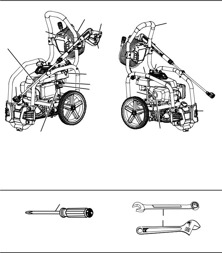
Fig. 1
|
F |
I |
|
|
|
|
|
G |
|
|
|
|
|
|
|
E |
|
|
|
D |
|
H |
|
|
|
|
|
|
|
|
|
|
O |
N |
|
|
|
|
|
|
L |
|
|
|
A |
M |
|
|
|
|
J |
|
B |
|
|
|
|
|
C
P
K
A - 5-in-1 change over nozzle (buse à permutation 5 en 1, boquilla intercambiable 5 en 1)
B- Oil cap/dipstick (bouchon / jauge d’huile, tapa del aceite con varilla de nivel)
C- Detergent tank (réservoir de détergent, tanque de detergente)
D- Spray wand (lance de pulvérisation, tubo rociador)
E- Hose storage (rangement de tuyau, almacenamiento de la manguera)
F- High pressure hose (tuyau haute pression, manguera de alta presión)
G- Handle (poignée, mango)
H- Trigger handle (poignée à gâchette, mango del gatillo)
I- Trigger with lock out (gâchette avec verrou, gatillo con seguro)
J- On/off switch (commutateur marche/arrêt, interruptor de encendido/ apagado)
K- Fuel valve (robinet de carburant, válvula de combustible)
L- Fuel tank (réservoir de carburant, tanque del combustible)
M- Choke lever (levier de volet de départ, palanca del anegador)
N- Fuel cap (bouchon du réservoir, tapa del tanque de combustible)
O- Starter grip and rope (poignée du lanceur avec corde, mango del arrancador con cuerda)
P- Muffler (silencieux, silenciador)
Fig. 2
A
B
A - Phillips screwdriver (tournevis phillips, destornillador phillips)
B- Combination wrench or adjustable wrench (clé mixte ou clé a molette, llave de combinación o llave ajustable)
ii
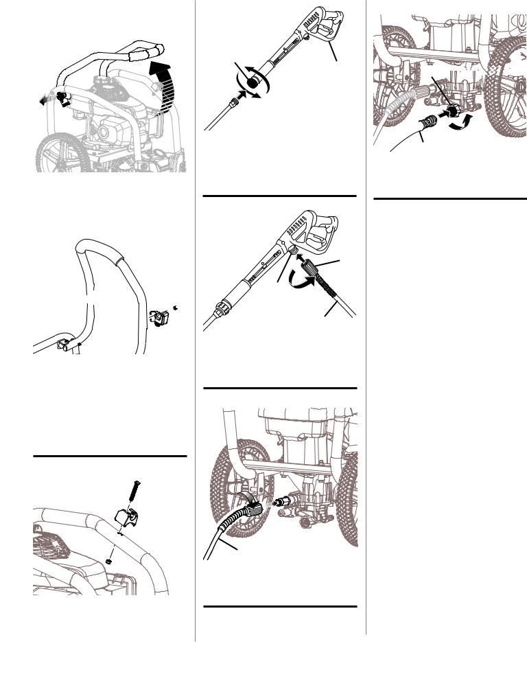
Fig. 3
B
A
A - Handle release knob (bouton de dégagement de la poignée, perilla de liberación del mango)
B - Handle (poignée, mango)
Fig. 4
C D
A F D B 

E
A
A- Screw (vis, tornillo)
B- Hose storage (rangement de tuyau, almacenamiento de la manguera)
C- Handle (poignée, mango)
D- Hex nut (écrou hexagonal, tuerca hexagonal)
E- Trigger handle holder (support de la poignée
àgâchette, almacenamiento de mango del gatillo)
F- Washer (rondelle, arandela)
Fig. 5
C
B
A
A - Hex nut (écrou hexagonal, tuerca hexagonal) B - Spray wand holder (support de la lance
d’arrosage, soporte del tubo rociador) C - Screw (vis, tornillo)
Fig. 6
B
A
 C
C
A - Trigger handle (poignée à gâchette, mango del gatillo)
B - Connector (connecteur, conector)
C - Spray wand (lance de pulvérisation, tubo rociador)
Fig. 7
A
B
C
A - Collar (collier, casquillo)
B - Inlet coupler (raccord d’entrée, acoplador de entrada)
C - High pressure hose (tuyau haute pression, manguera de alta presión)
Fig. 8
B
A
A - High pressure hose (tuyau haute pression, manguera de alta presión)
B - Collar (collier, casquillo)
Fig. 9
A 


 C B
C B
A - Water intake (prise d’eau, entrada de agua) B - Screen (tamis, cedazo)
C - Garden hose (tuyau d’arrosage, manguera de jardín)
Fig. 10
B
A
A - Oil cap/dipstick (bouchon / jauge d’huile, tapa del aceite con varilla de nivel)
B - Funnel (entonnoir, embudo)
Fig. 11
B
A
A- Funnel (entonnoir, embudo)
B- Fuel cap (bouchon de carburant, tapa del tanque de combustible)
iii
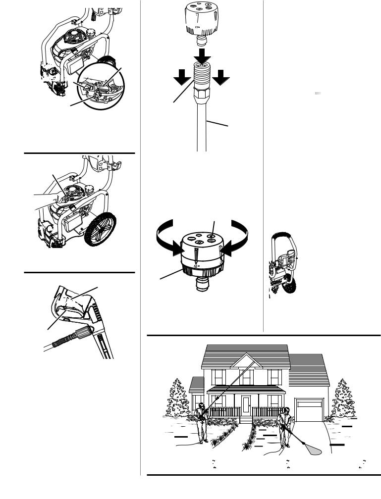
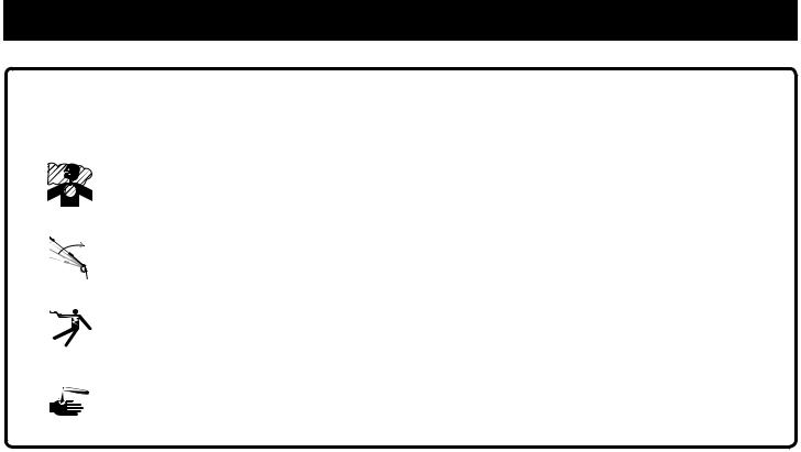
Fig. 12


 B
B 


 A
A 


C
A- On/off switch (commutateur marche / arrêt, interruptor de encendido/apagado)
B- Choke lever (levier de volet de départ, palanca del anegador)
C- Fuel valve (robinet de carburant, válvula de combustible)
Fig. 13
A


 SOAP
SOAP


A - Starter grip and rope (poignée du lanceur avec corde, mango del arrancador con cuerda)
Fig. 14
A
B 


C
A - Slot (encoche, ranura)  B - Lock out (verrouillage, seguro) C - Trigger (gâchette, gatillo)
Fig. 15 |
Fig. 18 |
A 


“CLICK”
DÉCLIC
CLIC
B |
|
|
C |
|
|
A - 5-in-1 change over nozzle (buse à |
Fig. 19 |
|
permutation 5 en 1, boquilla intercambiable |
|
|
5 en 1) |
|
|
B - Quick-connect collar (collier à ressort, |
|
|
casquillo de conexión rápida) |
|
|
C - Spray wand (lance de pulvérisation, tubo |
|
|
rociador) |
|
|
|
|
|
Fig. 16 |
|
|
B |
|
|
A
A - 5-in-1 change over nozzle (buse à permutation 5 en 1, boquilla intercambiable 5 en 1)
B - Spray selector (sélecteur de jets , selector de rociado )
Fig. 17
A- Long range detergent [


 ] (détergent à longue portée [


 ], detergente de gran alcance [


 ])
])
B- Short range detergent [
 ] (détergent à courte portée [
 ], detergente corto alcance [
 ])
])
iv

Fig. 20 |
Fig. 22 |
Fig. 24 |
TO MOVE THE PRESSURE WASHER
POUR DÉPLACER L’ÉQUIPEMENT
PARA MOVER LA MÁQUINA


 SOAP
SOAP


A 


C B
A - Air filter cover (couvercle du filtre à air, tapa del filtro de aire)
B - Air filter (filtre à air, filtro de aire) C - Tabs (ergots, orejetas)
Fig. 23
Fig. 21 |
A |
|
|
A |
B |
A - .028 in. - .032 in. (0.7 mm - 0.8 mm) |
|
[0,028 po - 0,032 po (0,7 mm - 0,8 mm) |
|
0,028 pulg. - 0,032 pulg. (0,7 mm - 0,8 mm)] |
A- Paper clip (pièces de papier, clips de papel)
B- 5-in-1 change over nozzle (buse à permutation 5 en 1, boquilla intercambiable 5 en 1)
SOAP
A
C 


 B
B
A - Oil cap / dipstick (bouchon/jauge d’huile, tapa del aceite con varilla de nivel)
B- Oil fill hole (orifice de remplissage d’huile, agujero de llenado de aceite)
C- Container (récipient, recipiente)
Fig. 25
TO STORE THE MACHINE
POUR REMISER L’ÉQUIPEMENT PARA GUARDAR LA MÁQUINA
v

TABLE OF CONTENTS
TABLE DES MATIÈRES / ÍNDICE DE CONTENIDO
Introduction....................................................................................................................................................................... |
2 |
Introduction / Introducción |
|
Important Safety Instructions............................................................................................................................................ |
3 |
Instructions importantes concernant la sécurité / Instrucciones de seguridad importantes |
|
Specific Safety Rules........................................................................................................................................................ |
4 |
Règles de sécurité particulières / Reglas de seguridad específicas |
|
Symbols......................................................................................................................................................................... |
5-6 |
Symboles / Símbolos |
|
Features............................................................................................................................................................................ |
7 |
Caractéristiques / Características |
|
Assembly........................................................................................................................................................................ |
8-9 |
Assemblage / Armado |
|
Operation................................................................................................................................................................... |
10-13 |
Utilisation / Funcionamiento |
|
Maintenance............................................................................................................................................................... |
14-16 |
Entretien / Mantenimiento |
|
Troubleshooting............................................................................................................................................................... |
17 |
Dépannage / Solución de problemas |
|
Warranty.......................................................................................................................................................................... |
18 |
Garantie / Garantía |
|
Parts Ordering and Service................................................................................................................................ |
Back Page |
Commande de pièces et réparation / Pedidos de piezas y servicio...................................... |
Page arrière / Pág. posterior |
INTRODUCTION
INTRODUCTION / INTRODUCCIÓN
This product has many features for making its use more pleasant and enjoyable. Safety, performance, and dependability have been given top priority in the design of this product making it easy to maintain and operate.
* * *
Ce produit offre de nombreuses fonctions destinées à rendre son utilisation plus plaisante et satisfaisante. Lors de la conception de ce produit, l’accent a été mis sur la sécurité, les performances et la fiabilité, afin d’en faire un outil facile à utiliser et à entretenir.
* * *
Este producto ofrece numerosas características para hacer más agradable y placentero su uso. En el diseño de este producto se ha conferido prioridad a la seguridad, el desempeño y la fiabilidad, por lo cual se facilita su manejo y mantenimiento.
2 — English

IMPORTANT SAFETY INSTRUCTIONS
 WARNING:
Read and understand all instructions. Failure to follow all instructions listed below may result in electric shock, fire and/or carbon monoxide poisoning which will cause death or serious personal injury.
READ ALL INSTRUCTIONS
Know your tool. Read the operator’s manual carefully. Learn the machine’s applications and limitations as well as the specific potential hazards related to this tool.
Keep guards in place and in working order. Never operate the tool with any guard or cover removed. Make sure all guards are operating properly before each use.
Remove adjusting keys and wrenches. Form habit of checking to see that keys and adjusting wrenches are removed from tool before turning it on.
To reduce the risk of injury, keep children and visitors away. All visitors should wear safety glasses and be kept a safe distance from work area.
Keep the area of operation clear of all persons, particularly small children, and pets.
Do not start or operate the engine in a confined space, building, near open windows, or in other unventilated space where dangerous carbon monoxide fumes can collect. Carbon monoxide, a colorless, odorless, and extremely dangerous gas, can cause unconsciousness or death.
Use right tool. Don’t force tool or attachment to do a job it was not designed for. Don’t use it for a purpose not intended.
Dress properly. Do not wear loose clothing, gloves, neckties, or jewelry. They can get caught and draw you into moving parts. Rubber gloves and nonskid footwear are recommended when working outdoors. Also wear protective hair covering to contain long hair.
Do not operate the equipment while barefoot or when wearing sandals or similar lightweight footwear. Wear protective footwear that will protect your feet and improve your footing on slippery surfaces.
Exercise caution to avoid slipping or falling.
Always wear eye protection with side shields marked to comply with ANSI Z87.1. Following this rule will reduce the risk of serious personal injury.
Don’t overreach or stand on unstable support. Keep proper footing and balance at all times.
Use only recommended accessories. The use of improper accessories may cause risk of injury.
Follow the maintenance instructions specified in this manual.
Checkdamagedparts.Beforefurtheruseofthetool, a guard or other part that is damaged should be carefully checked to determine that it will operate properly and perform its intended function. Check for alignment of moving parts, binding of moving parts, breakage of parts, mounting, and any other conditions that may affect its operation. A guard or other part that is damaged must be properly repaired or replaced by an authorized service center to avoid risk of personal injury.
Never leave tool running unattended. Turn power off.
Don’t leave tool until it comes to a complete stop.
Keep the engine free of grass, leaves, or grease to reduce the chance of a fire hazard.
Keep the exhaust pipe free of foreign objects.
Follow manufacturer’s recommendations for safe loading, unloading, transport, and storage of machine.
Be thoroughly familiar with controls. Know how to stop the product and bleed pressure quickly.
Keep tool dry, clean, and free from lubricant and grease.Alwaysuseacleanclothwhencleaning.Neveruse brake fluids, gasoline, petroleum-based products, or any solvents to clean tool.
Stay alert and exercise control. Watch what you are doing and use common sense. Do not operate tool when you are tired. Do not rush.
Do not operate the product while under the influence of drugs, alcohol, or any medication.
Check the work area before each use. Remove all objects such as rocks, broken glass, nails, wire, or string which can be thrown or become entangled in the machine.
Do not use tool if switch does not turn it off. Have defective switches replaced by an authorized service center.
Before cleaning, repairing, or inspecting, shut off the engine and make certain all moving parts have stopped. Disconnect the spark plug wire, and keep the wire away from the plug to prevent accidental starting.
Avoid dangerous environment. Don’t use in damp or wet locations or expose to rain. Keep work area well lit.
Never use in an explosive atmosphere. Normal sparking of the motor could ignite fumes.
Do not operate while smoking or near an open flame.
Do not operate around dry brush, twigs, cloth rags, or other flammable materials.
WARNING: Risk of injection or injury – Do not direct discharge stream at persons.
3 — English

SPECIFIC SAFETY RULES
Use caution when positioning the pressure washer for use. Warm air from the engine could cause discolored spots on grass.
Never direct a water stream toward people or pets, or any electrical device.
Before starting any cleaning operation, close doors and windows. Clear the area to be cleaned of debris, toys, outdoor furniture, or other objects that could create a hazard.
Never pick up or carry a machine while the engine is running.
Never start the machine if ice has formed in any part of the equipment.
Do not use acids, alkalines, solvents, flammable material, bleaches, or industrial grade solutions in this product. These products can cause physical injuries to the operator and irreversible damage to the machine.
Always operate the machine on a level surface. If the engine is on an incline, it could seize due to improper lubrication (even at the maximum lubricant level).
WARNING: High pressure jets can be dangerous if subject to misuse. The jet must not be directed at persons, animals, electrical devices, or the machine itself.
Hold the handle and wand securely with both hands.
Expect the trigger handle to move when the trigger is pulled due to reaction forces. Failure to do so could cause loss of control and injury to yourself and others.
Never attempt to make any adjustments while the engine (motor) is running (except where specifically recommended by the manufacturer).
Protective covers must always cover rotating parts when the engine is running.
Keep cooling air intake (recoil starter area) and muffler side of the engine at least 3 feet away from buildings, obstructions, and other combustible objects.
Keep the engine away from flammables and other hazardous materials.
Keep away from hot parts. The muffler and other engine parts become very hot; use caution.
Do not touch the spark plug and ignition cable when starting and operating the engine.
Check fuel hoses and joints for looseness and fuel leakage before each use.
Check bolts and nuts for looseness before each use. A loose bolt or nut may cause serious engine problems.
Always refuel outdoors. Never refuel indoors or in a poorly ventilated area.
Never store the machine with fuel in the fuel tank inside a building where ignition sources are present, such as hot water and space heaters, clothes dryers, and the like.
If the fuel tank has to be drained, do this outdoors.
To reduce the risk of fire and burn injury, handle fuel with care. It is highly flammable.
Do not smoke while handling fuel.
Add fuel before starting the engine. Never remove the cap of the fuel tank or add fuel while the engine is running or when the engine is hot.
Loosen fuel cap slowly to release pressure and to keep fuel from escaping around the cap.
Replace all fuel tank and container caps securely.
Wipe spilled fuel from the unit. Move 30 feet away from refueling site before starting engine.
If fuel is spilled, do not attempt to start the engine but move the machine away from the area of spillage and avoid creating any source of ignition until fuel vapors have dissipated.
Never attempt to burn off spilled fuel under any circumstances.
Before storing, allow the engine to cool and drain fuel from the unit.
Store fuel in a cool, well-ventilated area, safely away from spark and/or flame-producing equipment.
Store fuel in containers specifically designed for this purpose.
Empty fuel tank and restrain the unit from moving before transporting in a vehicle.
When servicing use only identical replacement parts.
Use of any other parts may create a hazard or cause product damage.
ONLY use cold water.
Make sure minimum clearance of 3 feet is maintained from combustible materials.
Never spray close to the surface to be cleaned as you can damage the surface.
After stopping the engine, always pull the trigger on the trigger handle to relieve stored pressure in the high pressure hose. Failure to do so could result in serious personal injury.
For outdoor use only.
Ensure the high pressure hose is properly connected before using the product.
Save these instructions. Refer to them frequently and use them to instruct other users. If you loan someone this tool, loan them these instructions also.
4 — English

SYMBOLS
The following signal words and meanings are intended to explain the levels of risk associated with this product.
SYMBOL SIGNAL |
MEANING |
|
|
|
|
DANGER: |
Indicates an imminently hazardous situation, which, if not avoided, will result |
|
in death or serious injury. |
||
|
||
|
|
|
WARNING: |
Indicates a potentially hazardous situation, which, if not avoided, could result |
|
in death or serious injury. |
||
|
||
|
|
|
CAUTION: |
Indicates a potentially hazardous situation, which, if not avoided, may result in |
|
minor or moderate injury. |
||
|
||
|
|
|
NOTICE: |
(Without Safety Alert Symbol) Indicates important information not related to an |
|
injury hazard, such as a situation that may result in property damage. |
||
|
Some of the following symbols may be used on this product. Please study them and learn their meaning for safe operation of this product.
SYMBOL |
NAME |
EXPLANATION |
|
Safety Alert |
Indicates a potential personal injury hazard. |
|
Read Operator’s Manual |
To reduce the risk of injury, user must read and understand |
|
operator’s manual before using this product. |
|
|
|
|
|
Eye Protection |
Always wear eye protection with side shields marked to comply |
|
with ANSI Z87.1. |
|
|
|
|
|
Wet Conditions Alert |
Do not expose to rain or use in damp locations. |
|
Hot Surface |
To reduce the risk of injury or damage, avoid contact with any |
|
hot surface. |
|
|
|
|
|
|
|
|
To reduce the risk of injection or injury, never direct a water |
|
|
|
|
|
|
|
|
|
|
Risk of Injections |
stream towards people or pets or place any body part in the |
|
|
|
|
stream. Leaking hoses and fittings are also capable of causing |
|
|
|
|
|
|
|
|
|
|
|
|
injection injury. Do not hold hoses or fittings. |
|
|
|
|
|
|
|
|
|
|
|
|
|
|
|
|
Risk of Explosion |
Fuel and its vapors are explosive and can cause severe burns |
|
|
|
|
||
|
|
|
|
or death. |
|
|
|
|
|
|
|
|
|
|
|
|
|
|
|
|
|
|
|
|
|
|
|
Risk of Fire |
Fuel and its vapors are extremely flammable and explosive. Fire |
|
|
|
|
||
|
|
|
|
can cause severe burns or death. |
|
|
|
|
|
|
|
|
|
|
|
|
|
5 — English
SYMBOLS
Some of the following symbols may be used on this product. Please study them and learn their meaning for safe operation of this product.
SYMBOL |
NAME |
EXPLANATION |
||
|
|
|
|
|
|
|
|
|
Gas products emit carbon monoxide, an odorless, colorless, |
|
|
|
|
|
|
|
|
Toxic Fumes |
poison gas. Breathing carbon monoxide can cause nausea, |
|
|
|
|
fainting, or death. |
|
|
|
|
|
|
|
|
|
|
|
|
|
Kickback |
To reduce the risk of injury from kickback, hold the spray wand |
|
|
|
||
|
|
|
securely with both hands when the machine is on. |
|
|
|
|
|
|
|
|
|
|
|
|
|
|
|
|
|
|
|
Electric Shock |
Failure to use in dry conditions and to observe safe practices |
|
|
|
||
|
|
|
can result in electric shock. |
|
|
|
|
|
|
|
|
|
|
|
|
|
|
|
|
|
|
|
|
To reduce the risk of injury or damage, DO NOT USE ACIDS, |
|
|
|
|
|
|
|
|
Chemical Burns |
ALKALINES, BLEACHES, SOLVENTS, FLAMMABLE MATERIAL, |
|
|
|
|
OR INDUSTRIAL GRADE SOLUTIONS in this product. |
|
|
|
|
|
|
|
|
|
|
6 — English
|
FEATURES |
PRODUCT SPECIFICATIONS |
|
Fuel Tank Capacity...................................................................................................................................................... |
0.96 gal |
Honda GCV190 engine.................................................................................................................................................. |
187cc |
Maximum Pounds Per Square Inch Pressure*.......................................................................................................... |
3,100 psi |
Maximum Gallons Per Minute*................................................................................................................................... |
2.5 gpm |
Maximum Inlet Water Temperature................................................................................................................................. |
104˚F |
*Max. rating determined by PWMA Standard 101 |
|
KNOW YOUR PRESSURE WASHER
See Figure 1.
The safe use of this product requires an understanding of the information on the tool and in this operator’s manual as well as a knowledge of the project you are attempting. Before use of this product, familiarize yourself with all operating features and safety rules.
5-IN-1 CHANGE OVER NOZZLE
The 5-in-1 Change Over Nozzle makes it easy to change spray patterns.
AUTOMATIC DETERGENT INJECTION SYSTEM
Pour pressure washer detergent into the detergent tank to apply detergent quickly and easily to your cleaning project. Use of the soap nozzle will activate the detergent injector at a 20:1 dilution ratio.
FUEL TANK
This fuel tank has a maximum capacity of 0.96 gal. Use unleaded automotive gasoline in the engine.
HONDA GCV190 ENGINE
This Honda engine enables the pressure washer to achieve 3,100 psi (pounds per square inch) at a rate of 2.5 gpm (gallons per minute). Please read the engine manual included with this product.
HOSE STORAGE
Once the high pressure hose is rolled, hang it on the back of the machine using the stretch strap to secure in place.
IDLE DOWN
The engine idle speed is automatically reduced when the trigger is released. This feature increases fuel efficiency, reduces the noise level, and decreases wear and tear over the life of the pressure washer.
ON/OFF SWITCH
The on/off switch is used in combination with the starter grip and rope to start the engine. It is also used to turn the engine off.
STARTER GRIP AND ROPE
The starter grip and rope is pulled to start the machine.
THERMAL RELIEF VALVE
This pump feature will prevent water temperatures from reaching harmful levels by releasing a small amount of water. Once the water has drained, the thermal relief valve will reset itself.
TRIGGER HANDLE
The trigger handle has a gripping surface that provides added control of the spray wand and helps reduce fatigue.
TRIGGER WITH LOCK OUT
Pulling the trigger releases a stream of water for high pressure cleaning. The lock out provides protection against unauthorized use.
7 — English

ASSEMBLY
UNPACKING
This product requires assembly.
nCarefully remove the product and any accessories from the box. Make sure that all items listed in the packing list are included.
NOTE: This tool is heavy. To avoid back injury, lift with your legs, not your back, and get help when needed.
 WARNING:
Do not use this product if any parts on the Packing List are already assembled to your product when you unpack it. Parts on this list are not assembled to the product by the manufacturer and require customer installation. Use of a product that may have been improperly assembled could result in serious personal injury.
nInspect the tool carefully to make sure no breakage or damage occurred during shipping.
nDo not discard the packing material until you have carefully inspected and satisfactorily operated the tool.
nIf any parts are damaged or missing, please call 1-800-860-4050 for assistance.
PACKING LIST
Pressure Washer
25 ft. High Pressure Hose Trigger Handle Holder Spray Wand Holder Screw (3)
Nut (3) Trigger Handle Spray Wand
5-in-1 Change-Over Nozzle Washer
4-Cycle Engine Lubricant (SAE 30 or SAE 10W30) Disposable Funnel
High Pressure Hose Storage Operator’s Manual
 WARNING:
If any parts are damaged or missing do not operate this product until the parts are replaced. Use of this product with damaged or missing parts could result in serious personal injury.
 WARNING:
Do not attempt to modify this product or create accessories not recommended for use with this product. Any such alteration or modification is misuse and could result in a hazardous condition leading to possible serious personal injury.
 WARNING:
To prevent accidental starting that could cause serious personal injury, always disconnect the engine spark plug wire from the spark plug when assembling parts.
TOOLS NEEDED
See Figure 2.
The following tools (not included or drawn to scale) are needed for assembly:
nCombination Wrench or Adjustable Wrench
nPhillips Screwdriver
RAISING AND LOWERING THE HANDLE
See Figure 3.
nTo raise the handle: pull the handle up until the handle release knob snaps through the locking hole to secure the handle in place.
nTo lower the handle: pull the handle release knob out then lower the handle to the position shown in figure 3.
INSTALLING TRIGGER HANDLE HOLDER, SPRAY WAND HOLDER, AND HOSE STORAGE
See Figure 4 - 5.
nRaise handle as described in the Raising and Lowering Handle section.
nPlace hose storage onto the handle as shown.
nAlign the holes in the hose storage with the holes in the handle.
nInsert screw through the holes in the left side of the handle and hose storage.
nPlace hex nut onto screw and tighten securely.
nPlace the trigger handle holder onto the handle as shown.
nAlign the holes in the trigger handle holder with the holes in the hose storage and the handle.
nInsert screw through the holes in handle, hose storage, and trigger handle holder.
nSlide washer onto screw. Then, place nut onto screw and tighten securely.
nPlace spray wand holder onto pressure washer frame.
nAlign the holes in the spray wand holder with the holes in the pressure washer frame.
nInsert screw through the holes in the spray wand holder and the pressure washer frame.
nPlace nut onto screw and tighten securely.
ASSEMBLING THE TRIGGER HANDLE
See Figure 6.
nPlace the threaded end of the spray wand in the connector on the end of the trigger handle.
nTurn the connector clockwise until it stops. This secures the spray wand in place.
8 — English

ASSEMBLY
CONNECTING HIGH PRESSURE HOSE TO TRIGGER HANDLE
See Figure 7.
nScrew the collar on the high pressure hose into the trigger handle inlet coupler by turning the hose collar clockwise. Tighten securely.
NOTE: Be careful to avoid cross-threading, which can cause the trigger handle to leak during use.
nPull on the hose to be certain it is properly secured.
CONNECTING THE HIGH PRESSURE HOSE TO THE PUMP
See Figure 8.
nCompletely uncoil and straighten the high pressure hose to prevent kinks.
NOTE: See Using the High Pressure Hose in Operation for more information about using the high pressure hose.
nAlign the collar on the threaded nipple on the pump.
nInsert the nozzle on the end of the high pressure hose collar into the threaded nipple.
nTurn the collar clockwise to tighten the hose securely to the pump.
NOTE: Be careful to avoid cross-threading, which can cause the hose to leak during use.
nPull on the hose to be certain it is properly secured.
CONNECTING THE GARDEN HOSE TO THE PRESSURE WASHER
See Figure 9.
NOTICE:
Always observe all local regulations when connnecting hoses to the water main. Some areas have restrictions against connecting directly to public drinking water supply to prevent the feedback of chemicals into the drinking water supply. Direct connection through a receiver tank or backflow preventer is usually permitted.
The water supply must come from a water main. NEVER use hot water or water from pools, lakes, etc. Before connecting the garden hose to the pressure washer:
nRun water through the hose for 30 seconds to clean any debris from the hose.
nInspect the screen in the water intake.
nIf the screen is damaged, do not use the machine until the screen has been replaced.
nIf the screen is dirty, clean it before connecting the garden hose to the machine.
To connect the garden hose to the machine:
nCompletely uncoil the garden hose or remove completely from reel to prevent kinks.
NOTE: There must be a minimum of 10 feet of unrestricted hose between the pressure washer intake and the hose faucet or shut off valve (such as a “Y” shut off connector).
nWith the hose faucet turned completely off, attach the end of the garden hose to the water intake. Tighten by hand.
NOTICE:
Do not run the pressure washer pump without water supply connected and turned on, as this may damage the high pressure seals and decrease pump life. Completely unwind the hose from its reel or coil and make sure the hose is not being restricted by tires, rocks, or any other objects that may lessen or prevent water flow to the pressure washer.
DO NOT OVERTILT THE UNIT!
9 — English

OPERATION
 WARNING:
Do not allow familiarity with this product to make you careless. Remember that a careless fraction of a second is sufficient to inflict serious injury.
ADDING/CHECKING ENGINE LUBRICANT
See Figure 10.
NOTE: This machine has been shipped with approximately 2 oz. of lubricant in the engine from testing. You must add lubricant to the engine before starting it the first time.
 WARNING:
Always wear eye protection with side shields marked to comply with ANSI Z87.1. Failure to do so could result in objects being thrown into your eyes resulting in possible serious injury.
 WARNING:
Do not use any attachments or accessories not recommendedbythemanufacturerofthisproduct.Theuseof attachments or accessories not recommended can result in serious personal injury.
 WARNING:
Never direct a water stream toward people or pets, or any electrical device. Failure to heed this warning could result in serious injury.
NOTICE:
This product is not equipped with a spark arrestor and cannot be used on U.S. forest lands; in addition, product users must comply with Federal, State, and local fire prevention regulations. Check with appropriate authorities. Refer to accompanying engine manual for maintenance and replacement parts.
APPLICATIONS
You may use this tool around the house for cleaning most small to large horizontal or vertical exterior surfaces, smaller exterior objects and structures, and outdoor equipment and tools.* You can:
Clean or remove mold and mildew from weathered decks, driveways, patios, walkways, sidewalks, etc.
Remove dirt from various exterior vertical surfaces such as house exteriors, siding, fences, brick, concrete or stone walls, etc.
Wash boats, outdoor furniture, powered or non-powered garden equipment, gutters, window screens, grills, playground equipment, etc.
*Always test in an inconspicuous area first.
NOTICE:
Any attempt to start the engine without adding lubricant will result in engine failure.
To add engine lubricant:
nPlace pressure washer on a flat, level surface. Do not tilt.
nUnscrew the oil cap / dipstick by turning counterclockwise.
nUsing 4-stroke engine lubricant (SAE 30 or SAE 10W30), add engine lubricant until the fluid level rises to the upper portion of the hatched area on the dipstick (12 oz., 4-cycle engine lubricant provided). Do not overfill.
nReplace the oil cap / dipstick and securely tighten.
To check the engine lubricant level:
nPlace pressure washer on a flat, level surface. Do not tilt.
nUnscrew the oil cap/dipstick by turning counterclockwise.
nWipe dipstick clean and re-seat in hole; do not rethread.
nRemovedipstickagainandchecklubricantlevel.Lubricant level should fall within the hatched area on the dipstick.
nIf level is low, add engine lubricant until the fluid level rises to the upper portion of the hatched area on the dipstick.
nReplace and secure the oil cap/dipstick.
NOTICE:
Any attempt to start the engine without adding lubricant will result in engine failure.
OXYGENATED FUELS
NOTICE:
Do not use E15 or E85 fuel (or fuel containing greater than 10% ethanol) in this product. It is a violation of federal law and will damage the unit and void your warranty.
Fuel system damage or performance problems resulting from the use of an oxygenated fuel containing more than the percentage of oxygenates stated below are not covered under warranty.
Ethanol. Gasoline containing up to 10% ethanol by volume (commonly referred to as E10) is acceptable. E15 and E85 are not.
10 — English

OPERATION
ADDING GASOLINE TO THE FUEL TANK
See Figure 11.
 WARNING:
Gasoline and its vapors are highly flammable and explosive. To prevent serious personal injury and property damage, handle gasoline with care. Keep away from ignition sources, handle outdoors only, do not smoke while adding fuel, and wipe up spills immediately.
When adding gas to the pressure washer, make sure the unit is sitting on a flat, level surface. If the engine is hot, let the pressure washer cool before adding gas. ALWAYS fill the fuel tank outdoors with the machine turned off.
NOTE: This is a 4-cycle engine. DO NOT mix fuel and lubricant together.
nMix fuel stabilizer with gasoline according to fuel stabilizer manufacturer’s directions.
nBefore removing the fuel cap, clean the area around it. Remove the fuel cap.
nInsert a clean funnel into the fuel tank then slowly pour gasoline into the tank. Fill tank to approximately 1-1/2 in. below the top of the tank neck (this allows for fuel expansion).
nReplace fuel cap and tighten until the cap “clicks”.
nClean up any spills before starting the engine.
STARTING AND STOPPING THE PRESSURE WASHER
See Figures 12 - 13.
NOTICE:
Do not run the pressure washer pump without water supply connected and turned on, as this may damage the high pressure seals and decrease pump life. Completely unwind the hose from its reel or coil and make sure the hose is not being restricted by tires, rocks, or any other objects that may lessen or prevent water flow to the pressure washer.
Before starting the engine:
Connect all hoses.
NOTE: Make sure the pressure washer’s water intake screen is in place and unclogged before connecting garden hose.
Check all fluids (lubricant and gas).
Turn on the garden hose then squeeze the trigger to relieve air pressure; hold the trigger until a steady stream of water appears.
NOTE: Make sure the faucet is turned on fully and that there are no kinks or leaks in the hose.
To start the engine:
Turn the fuel valve to the ON position.
Pull choke out to the START position.
NOTE: If restarting after a brief stop (i.e., after refueling or moving), leave the choke lever in the RUN position.
Put the on/off switch in the ON position.
Grasp the starter grip and rope and pull slowly until resistance is felt. Give the starter grip and rope a short, brisk pull to start the engine.
NOTE: Do not allow the starter grip and rope to snap back after starting; return it gently to its original place.
Let engine run for several seconds, then push choke in to the RUN position.
To stop the engine:
Put the on/off switch in the OFF position.
Turn the fuel valve to the OFF position.
nShut off the water supply and pull trigger to release water pressure.
WARNING:
While operating and storing, keep at least 3 feet of clearance on all sides of this product, including overhead. Allow a minimum of 30 minutes of “cool down” time before storage. Keep all body parts, clothing, combustible materials, and hoses away from the muffler. Heat created by muffler and exhaust gases could be hot enough to cause serious burns, ignite combustible objects, and/ or damage high pressure hoses that can result in an injection injury.
USING THE SPRAY WAND TRIGGER
See Figure 14.
For greater control and safety, keep both hands on the trigger handle at all times.
nPull back and hold the trigger to operate the pressure washer.
nRelease the trigger to stop the flow of water through the nozzle.
To engage the lock out:
nPush up on the lock out until it clicks into the slot.
To disengage the lock out:
nPush the lock out down and into its original position.
To use the spray wand, start with the nozzle 1-2 ft. away from the cleaning surface. Carefully approach the surface just until the desired level of cleaning is achieved. If the spray is too close it can damage the cleaning surface.
11 — English

OPERATION
INSTALLING/REMOVING NOZZLE
See Figure 15.
WARNING:
NEVER change nozzles without locking the lock out on the trigger handle and NEVER point the wand at your face or at others. The quick-connect feature contains small springs that could eject the nozzle with some force. Failure to heed this warning could cause personal injury.
To connect the nozzle to the trigger handle:
nTurn off the pressure washer and shut off the water supply.
Pull trigger to release water pressure.
nEngage the lock out on the trigger handle by pushing up on the lock out until it clicks into the slot.
nPush the nozzle into the quick-connect collar until it clicks in place and is secured properly.
To disconnect the nozzle from the trigger handle once the cleaning job is complete:
nTurn off the pressure washer and shut off the water supply. Pull trigger to release water pressure.
nEngage the lock out on the trigger handle by pushing up on the lock out until it clicks into the slot.
nRemove the nozzle by placing hand over nozzle then pulling back the quick-connect collar.
USING THE 5-IN-1 CHANGE OVER NOZZLE
See Figure 16.
There are five spray pattern settings located on the 5-in-1 Change Over Nozzle. To select a spray pattern, rotate the spray selector to the desired setting. Refer to the Nozzle Selection Guide for more information about which setting to choose.
USING THE HIGH PRESSURE HOSE
The high pressure hose features an outer covering that provides strength to the hose. If the outer covering becomes damaged, the hose must be replaced immediately. Do not use a high pressure hose if the outer covering is damaged.
To prevent damage to the outer covering:
nInspect the hose before every use.
nFully unwrap and straighten hose before use.
NOZZLE SELECTION GUIDE
|
|
HIGH PRESSURE |
|
LOW PRESSURE |
|
|
|
|
(FOR SOAP OR |
||
|
(NO SOAP WHEN USING THESE NOZZLES) |
||||
|
GENTLE RINSE) |
||||
|
|
|
|
||
|
0º |
25º |
40º |
Long Range |
Short Range |
ABRASIVE |
GENTLE |
|
|
|
|
Concrete, Brick, Masonry |
|
|
|
|
|
|
|||||
Siding, Gutters, House |
|
|
|
|
|
|
|
||||
Fencing, Deck, Patio |
|
|
|
|
|
|
|
||||
Lawn Equipment, Boat, RV |
|
|
|
|
|
|
|
||||
Recommended Nozzle Use With Caution for Certain Applications
12 — English

OPERATION
nDo not allow the high pressure hose to be kinked.
nKeep hose away from hot surfaces and sharp edges.
nDo not pull unit by high pressure hose.
nDo not allow hose to be crushed or wrapped around objects.
WASHING WITH DETERGENT
See Figures 17 - 19.
As sold, this unit is designed for use with “downstream” pressure washer detergents. To convert for use with “upstream” detergents, contact an authorized customer service center for more information.
USE ONLY DETERGENTS DESIGNED FOR PRESSURE WASHERS; Do not use household detergents, acids, alkalines, bleaches, solvents, flammable material, or industrial grade solutions, which can damage the pump. Many detergents may require mixing prior to use. Prepare cleaning solution as instructed on the solution bottle. Always test in an inconspicuous area before beginning.
nRemove the cap from the detergent tank and pour pressure washer detergent in the tank. Replace cap on tank.
NOTE: The machine setting of this unit is 20:1, which usually allows the use of 1 gallon pressure washer detergent without further dilution. Check your detergent instructions to be sure additional dilution is not necessary.
nInstall 5-in-1 Change Over Nozzle (if necessary). Rotate the spray selector on the nozzle to either the blue short
range detergent (
 ) or blue long range detergent (


 ) setting.
nSqueeze the trigger and wait approximately 5 seconds for the detergent to appear.
nSpray the detergent on a dry surface using long, even, overlapping strokes. To prevent streaking, do not allow detergent to dry on the surface.
For long range detergent application:
With the nozzle installed on the spray wand and the engine shut off, rotate the spray selector to the long range detergent [


 ] setting.
For short range detergent application:
With the nozzle installed on the spray wand and the engine shut off, rotate the spray selector to the short range detergent [
 ] setting.
Before shutting off the engine:
n Fill the detergent tank with clean water.
nSpray the clear water through the spray wand until the tank is empty.
nIf any soap remains in the spray, repeat with a second tank of clean water.
nShut off the engine.
NOTE: Shutting OFF ( O ) the engine WILL NOT relieve pressure in the system. Pull trigger to release water pressure.
RINSING WITH THE PRESSURE WASHER
nTurn off the pressure washer and shut off the water supply. Pull trigger to release water pressure.
nEngage the lock out on the trigger handle by pushing up on the lock out until it clicks into the slot.
nSelect the right nozzle setting for the job. See the chart on the previous page for selecting the appropriate nozzle setting.
nWhen using these settings, test a small area first to avoid surface damage.
nStart at the top of the area to be rinsed and work down, overlapping the strokes.
MOVING THE PRESSURE WASHER
See Figure 20.
NOTE: Never lift or carry this product using the handle and never place the unit in any position other than upright on its wheels.
nTurn the pressure washer off and ensure the fuel valve is closed.
nPull the handle up until the handle release knob snaps into the locking position (if not already up and locked). Ensure the lock is secured in the frame hole before moving.
nTilt the machine toward you slightly until it balances on the wheels then roll the machine to the desired position. Do not tilt forward or sideways when moving.
nDO NOT attempt to move the unit by pulling on any of the hoses.
HIGH ALTITUDE OPERATION
Specific modifications are needed for high-altitude operation. Please contact your authorized service center for important information regarding these modifications. Operating this engine without the proper altitude modification may increase the engine’s emissions and decrease fuel economy and performance.
13 — English
 Loading...