


OPERATOR’S MANUAL
MANUEL D’UTILISATION/MANUAL DEL OPERADOR
40 VOLT POWER HEAD
40V BLOC MOTEUR 40V CABEZAL MOTOR
RY40002
ALL VERSIONS
TOUTES LES VERSIONS
TODAS LAS VERSIONES
BATTERIES AND CHARGERS SOLD SEPARATELY
PILES ET CHARGEUR VENDUS SÉPARÉMENT
LAS BATERÍAS Y EL CARGADOR SE VENDEN POR SEPARADO
Your power head has been engineered and manufactured to our high standard for dependability, ease of operation, and operator safety. When properly cared for, it will give you years of rugged, trouble-free performance.
 WARNING: To reduce the risk of injury, the user must read and understand the operator’s manual before using this product.
Thank you for your purchase.
SAVE THIS MANUAL FOR FUTURE REFERENCE
Le bloc-moteur a été conçue et fabriquée conformément à nos strictes normes de fiabilité, simplicité d’emploi et sécurité d’utilisation.Correctemententretenue,ellevousdonneradesannées de fonctionnement robuste et sans problème.
 AVERTISSEMENT : Pour réduire les risques de blessures, l’utilisateur doit lire et veiller à bien comprendre le manuel d’utilisation avant d’employer ce produit.
Merci de votre achat.
Su cabezal motor ha sido diseñada y fabricada de conformidad con las estrictas normas para brindar fiabilidad, facilidad de uso y seguridad para el operador. Con el debido cuidado, le brindará muchos años de sólido y eficiente funcionamiento.
 ADVERTENCIA: Para reducir el riesgo de lesiones, el usuario debe leer y comprender el manual del operador antes de usar este producto.
Le agradecemos su compra.
CONSERVER CE MANUEL POUR |
GUARDE ESTE MANUAL PARA |
FUTURE RÉFÉRENCE |
FUTURAS CONSULTAS |
See this fold-out section for all the figures referenced in the operator’s manual.
Voir que cette section d’encart pour toutes les figures a adressé dans le manuel d’utilisation.
Vea esta sección de la página desplegable para todas las figuras mencionó en el manual del operador.
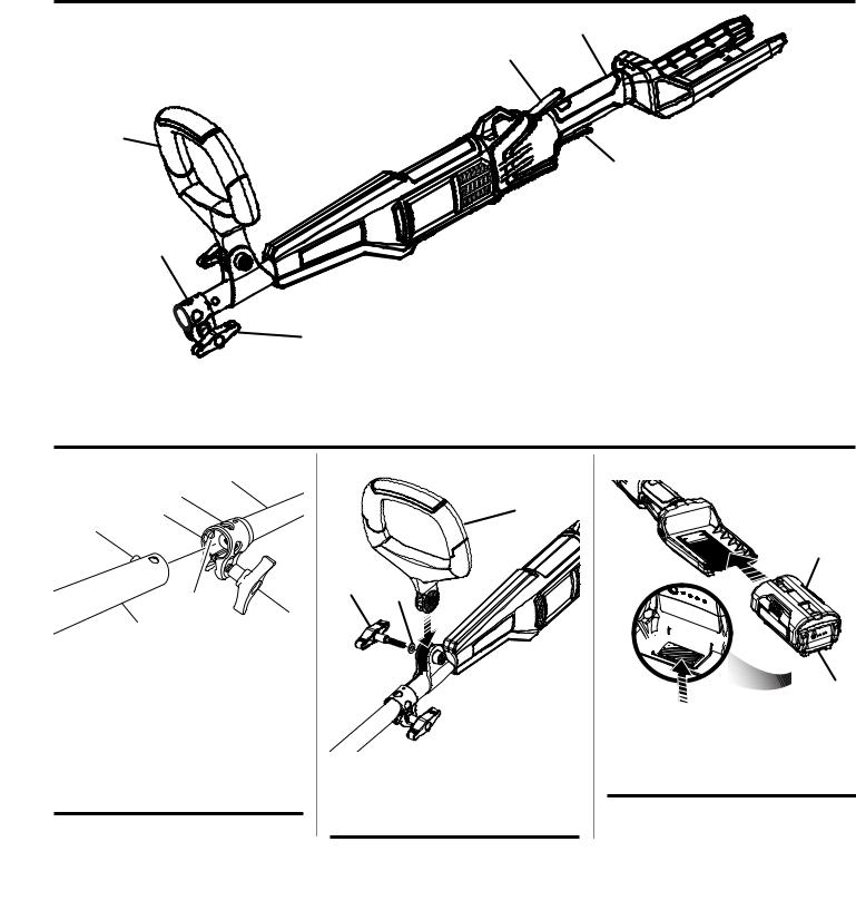
Fig. 1 |
D |
F
E
A
C
B
A - Switch trigger (gâchette, gatillo del interruptor) B - Knob (bouton, perilla)
C - Coupler (coupleur, acoplador)
D - Rear handle (poignée arrière, mango trasero)
E - Adjustable front handle (poignée avant réglable, mango delantero ajustable)
F - Trigger lock-out (gâchette avec verrou, gatillo con seguro)
Fig. 2
D
C
B
A
F
E
G
A - Button (bouton, botón)
B - Guide recess (logement guide, hueco guía) C - Coupler (coupleur, acoplador)
D - Power head shaft (arbre du bloc moteur, eje del cabezal motor)
E - Knob (bouton, perilla)
F - Positioning hole (trou de positionnement, orificio de posicionamiento)
G - Attachment shaft (arbre d’accessoire, eje del aditamento)
Fig. 3
A
B C
A - Front handle (poignée avant, mango delantero)
B - Wing bolt (boulon à oreilles, perno de mariposa)
C - Washer (rondelle, arandela)
Fig. 4
A
B 


B
A - Battery pack (bloc-piles, paquete de baterías)
B - Latch (loquet, pestillo)
ii

Fig. 5
B
A
A - Knob (bouton, perilla)
B - Adjustable front handle (poignée avant réglable, mango delantero ajustable)
Fig. 6
A
B
A - Trigger lock-out (gâchette avec verrou, gatillo con seguro)
B - Switch trigger (gâchette, gatillo del interruptor)
Fig. 7
PROPER EDGER ATTACHMENT
OPERATING POSITION
ACCESSOIRE COUPE-BORDURES
POSITION DE TRAVAIL
POSICIÓN CORRECTA PARA EL
ACCESORIO PARA CORTAR BORDES
Fig. 8
PROPER BLOWER ATTACHMENT
OPERATING POSITION
ACCESSOIRE SOUFFLANTE
POSITION DE TRAVAIL
POSICIÓN CORRECTA PARA EL
MANEJO DE ADITAMENTO PARA SOPLADOR
Fig. 9
PROPER STRAIGHT SHAFT TRIMMER
ATTACHMENT OPERATING POSITION
ACCESSOIRE TAILLE-BORDURES À ARBRE DROIT
POSITION DE TRAVAIL
POSICIÓN CORRECTA PARA EL MANEJO DE ADITAMENTO PARA RECORTADORA DE EJE RECTO
Fig. 10
PROPER CURVED SHAFT TRIMMER
ATTACHMENT OPERATING POSITION
ACCESSOIRE TAILLE-BORDURES À ARBRE
COURBÉE POSITION DE TRAVAIL
POSICIÓN CORRECTA PARA EL MANEJO DE ADITAMENTO PARA RECORTADORA DE EJE CURVO
Fig. 11
PROPER CULTIVATOR ATTACHMENT
OPERATING POSITION
ACCESSOIRE CULTIVATEUR POSITION DE TRAVAIL
POSICIÓN CORRECTA PARA EL
MANEJO DE ADITAMENTO PARA CULTIVAR
iii

TABLE OF CONTENTS
TABLE DES MATIÈRES / ÍNDICE DE CONTENIDO
Introduction....................................................................................................................................................................... |
2 |
Introduction / Introducción |
|
Important Safety Instructions......................................................................................................................................... |
3-4 |
Instructions importantes concernant la securite / Instrucciones de seguidad importantes |
|
Symbols............................................................................................................................................................................ |
5 |
Symboles / Símbolos |
|
Features............................................................................................................................................................................ |
6 |
Caractéristiques / Características |
|
Assembly........................................................................................................................................................................ |
6-7 |
Assemblage / Armado |
|
Operation....................................................................................................................................................................... |
8-9 |
Utilisation / Funcionamiento |
|
Maintenance...................................................................................................................................................................... |
9 |
Entretien / Mantenimiento |
|
Troubleshooting................................................................................................................................................................. |
9 |
Dépannage / Corrección de problemas |
|
Warranty.......................................................................................................................................................................... |
10 |
Garantie / Garantía |
|
Parts Ordering and Service................................................................................................................................ |
Back Page |
Commande de pièces et réparation / Pedidos de piezas y servicio.......................................................... |
Page arrière / Pág. posterior |
INTRODUCTION
INTRODUCTION / INTRODUCCIÓN
This product has many features for making its use more pleasant and enjoyable. Safety, performance, and dependability have been given top priority in the design of this product making it easy to maintain and operate.
* * *
Ce produit offre de nombreuses fonctions destinées à rendre son utilisation plus plaisante et satisfaisante. Lors de la conception de ce produit, l’accent a été mis sur la sécurité, les performances et la fiabilité, afin d’en faire un outil facile à utiliser et à entretenir.
* * *
Este producto ofrece numerosas características para hacer más agradable y placentero su uso. En el diseño de este producto se ha conferido prioridad a la seguridad, el desempeño y la fiabilidad, por lo cual se facilita su manejo y mantenimiento.
2 — English

IMPORTANT SAFETY INSTRUCTIONS
 WARNING!
When using electric gardening appliances, basic safety precautions should always be followed to reduce the risk of fire, electric shock and personal injury.
READ ALL INSTRUCTIONS
For safe operation, read and understand all instructions before using this product. Follow all safety instructions. Failure to follow all safety instructions listed below, can result in serious personal injury.
Do not allow children or untrained individuals to use this unit.
Check the work area before each use. Remove all objects such as rocks, broken glass, nails, wire, or string which can be thrown or become entangled in the machine.
Always wear eye protection with side shields marked to comply with ANSI Z87.1. Following this rule will reduce the risk of serious personal injury.
Use Safety Glasses – Always use face or dust mask if operation is dusty.
Protect your lungs. Wear a face or dust mask if the operation is dusty. Following this rule will reduce the risk of serious personal injury.
Dress Properly – Use of rubber gloves and substantial footwear is recommended when working outdoors. Wear heavy, long pants, long sleeves, boots, and gloves. Do not wear loose fitting clothing, short pants, sandals, or go barefoot. Do not wear loose clothing or jewelry. They can be caught in moving parts. Secure long hair above shoulder level to prevent entanglement in moving parts.
Keep children away – Keep all bystanders, children, and pets at least 50 ft. away.
Stayalert–Watchwhatyouaredoing.Usecommonsense. Do not operate this unit when you are tired, ill, upset, or under the influence of alcohol, drugs, or medication.
Do not operate in poor lighting.
Keep all parts of your body away from any moving part.
Do not operate power tools in explosive atmospheres, such as in the presence of flammable liquids, gases, or dust. Power tools create sparks which may ignite the dust or fumes.
Avoid body contact with grounded surfaces such as pipes, radiators, ranges, and refrigerators. There is an increased risk of electric shock if your body is grounded.
Avoid Dangerous Environments – Don’t expose appliance to rain or wet conditions. Water entering an appliance will increase the risk of electric shock.
Use Right Appliance – Do not use appliance for any job except that for which it is intended. Do not force tool. Use the correct tool for your application. The correct tool will do the job better and safer at the rate for which it is designed.
Don’t Force Appliance – It will do the job better and with less likelihood of a risk of injury at the rate for which it was designed.
Do not operate the equipment while barefoot or when wearing sandals or similar lightweight footwear. Wear protective footwear that will protect your feet and improve your footing on slippery surfaces.
Do not overreach – Keep firm footing and balance. Overreaching can result in loss of balance.
Avoid accidental starting – Be sure switch trigger is in the locked or off position before inserting battery pack. Carrying tools with your finger on the switch trigger or inserting the battery pack into a tool with the switch on invites accidents.
Do not use tool if switch trigger does not turn it on or off. Any tool that cannot be controlled with the switch trigger is dangerous and must be repaired.
Disconnect power head – Disconnect battery pack from the appliance before storing, servicing, or changing accessories such as cutting line. Such preventive safety measures reduce the risk of starting the tool accidentally.
Use only identical manufacturer’s replacement parts and accessories. Use of any other parts may create a hazard or cause product damage.
Maintain appliance with care – Replace string head if cracked, chipped, or damaged in any way. Be sure the string head is properly installed and securely fastened. Failure to do so can cause serious injury. Follow instructions for lubrication and changing accessories. Inspect chargercordperiodicallyand,ifdamaged,haveitreplaced. Keep power head handles dry, clean, and free from grease and oil.
Check Damaged Parts – Before further use of the appliance, a guard or other part that is damaged should be carefully checked to determine that it will operate properly and perform its function. Check for alignment of moving parts, binding of moving parts, breakage of parts, mounting and any other condition that may effect its operation. A guard or other part that is damaged should be properly repaired or replaced by an authorized service center unless indicated elsewhere in this manual.
Keep hands and feet away from cutting area.
Make sure all guards, straps, deflectors and handles are properly and securely attached.
Use only the manufacturer’s replacement string in the cutting head when using a string trimmer attachment. Do not use any other cutting attachment, for example, metal wire, rope, or the like. To install any other brand of
3 — English

IMPORTANT SAFETY INSTRUCTIONS
cutting head to the string trimmer attachment can result in serious personal injury.
Never operate unit without the grass deflector in place and in good condition.
Maintain a firm grip on both handles while trimming. Keep string head below waist level. Never cut with the string head located over 30 in. or more above the ground.
Store idle appliances indoors - When not in use, power head and attachments should be stored indoors in a dry, locked place out of the reach of children.
Never use flailing devices, wire or rope on any attachment.
Inspect area to be cut. Remove objects (rocks, broken glass, nails, wire, string, etc.) which can be thrown or become entangled in cutting head.
Keep the air vents clean and free of debris to avoid overheating the motor. Clean after each use.
Stop the unit and disconnect the power source when not in use. Carry the unit with the motor stopped.
Store out of the reach of children.
Do not hang unit so that the switch trigger is depressed.
Battery tools do not have to be plugged into an electrical outlet; therefore, they are always in operating condition. Be aware of possible hazards when not using your battery tool or when changing accessories. Following this rule will reduce the risk of electric shock, fire, or serious personal injury.
Do not charge battery tool in rain, or damp or wet location. Following this rule will reduce the risk of electric shock.
Do not use battery-operated appliance in rain.
Do not grasp the exposed cutting blades or cutting edges when picking up or holding the appliance.
Keep hands away from blades.
Do not allow power head to be used as a toy. Close attention is necessary when used by or near children.
Do not handle charger, including charger plug, and charger terminals with wet hands.
Use extra care when cleaning on stairs.
Do not use to pick up flammable or combustible liquids, such as gasoline, or use in areas where they may be present.
Remove or disconnect battery before servicing, cleaning or removing material from the gardening appliance.
Use battery only with charger listed. For use with 40V lithium-ion battery packs. See Tool/Appliance/Battery Pack/Charger Correlation Supplement 988000-842.
Do not dispose of the batteries in a fire. The cell may explode. Check with local codes for possible special disposal instructions.
Do not open or mutilate the batteries. Released electrolyte is corrosive and may cause damage to the eyes or skin. It may be toxic if swallowed.
Do not place battery tools or their batteries near fire or heat. This will reduce the risk of explosion and possibly injury.
Batteries can explode in the presence of a source of ignition, such as a pilot light. To reduce the risk of serious personal injury, never use any cordless product in the presence of open flame. An exploded battery can propel debris and chemicals. If exposed, flush with water immediately.
Do not crush, drop or damage battery pack. Do not use a battery pack or charger that has been dropped or received a sharp blow. A damaged battery is subject to explosion. Properly dispose of a dropped or damaged battery immediately.
Exercise care in handling batteries in order not to short the battery with conducting materials such as rings, bracelets, and keys. The battery or conductor may overheat and cause burns.
For best results, your battery tool should be charged in a location where the temperature is more than 50°F but less than 100°F. To reduce the risk of serious personal injury, do not store outside or in vehicles.
Under extreme usage or temperature conditions, battery leakage may occur. If liquid comes in contact with your skin, wash immediately with soap and water, then neutralize with lemon juice or vinegar. If liquid gets into your eyes, flush them with clean water for at least 10 minutes, then seek immediate medical attention. Following this rule will reduce the risk of serious personal injury.
Save these instructions. Refer to them frequently and use them to instruct others who may use this power tool. If you loan someone this power tool, loan them these instructions also.
ADDITIONAL SPECIFIC SAFETY RULES CAN BE FOUND IN THE APPLICABLE ATTACHMENT’S OPERATOR’S MANUAL
4 — English

SYMBOLS
The following signal words and meanings are intended to explain the levels of risk associated with this product.
SYMBOL |
SIGNAL |
MEANING |
|
|
|
|
DANGER: |
Indicates an imminently hazardous situation, which, if not avoided, will result |
|
in death or serious injury. |
|
|
|
|
|
|
|
|
WARNING: |
Indicates a potentially hazardous situation, which, if not avoided, could result |
|
in death or serious injury. |
|
|
|
|
|
|
|
|
CAUTION: |
Indicates a potentially hazardous situation, which, if not avoided, may result in |
|
minor or moderate injury. |
|
|
|
|
|
|
|
|
NOTICE: |
(Without Safety Alert Symbol) Indicates important information not related to an |
|
injury hazard, such as a situation that may result in property damage. |
|
|
|
Some of the following symbols may be used on this product. Please study them and learn their meaning. Proper interpretation of these symbols will allow you to operate the product better and safer.
SYMBOL |
NAME |
DESIGNATION/EXPLANATION |
|
Safety Alert |
Indicates a potential personal injury hazard. |
|
Read Operator’s |
To reduce the risk of injury, user must read and understand operator’s |
|
Manual |
manual before using this product. |
|
Eye Protection |
Always wear eye protection with side shields marked to comply |
|
with ANSI Z87.1. |
|
|
|
|
|
Wet Conditions Alert |
Do not expose to rain or use in damp locations. |
|
Keep Bystanders |
Keep all bystanders at least 50 ft. away. |
|
Away |
|
|
|
|
|
Ricochet |
Thrown objects can ricochet and result in personal injury or property |
|
damage. |
|
|
|
|
|
No Blade |
Do not install or use any type of blade on a product displaying this |
|
symbol. |
|
|
|
|
|
|
This product uses lithium-ion (Li-ion) batteries. Local, state, or federal |
|
Recycle Symbol |
laws may prohibit disposal of batteries in ordinary trash. Consult your |
|
local waste authority for information regarding available recycling and/ |
|
|
|
|
|
|
or disposal options. |
|
Direct Current |
Type or a characteristic of current |
no |
No Load Speed |
Rotational speed, at no load |
.../min |
Per Minute |
Revolutions, strokes, surface speed, orbits etc., per minute |
V |
Volts |
Voltage |
Hz |
Hertz |
Frequency (cycles per second) |
min |
Minutes |
Time |
|
|
5 — English |

FEATURES
KNOW YOUR POWER HEAD
See Figure 1.
The safe use of this product requires an understanding of the information on the tool and in this operator’s manual as well as a knowledge of the project you are attempting. Before use of this product, familiarize yourself with all operating features and safety rules.
ADJUSTABLE FRONT HANDLE
The front handle assembly can be adjusted for ease of operation and to help prevent loss of control.
HANDLE OVERMOLD
Handle overmold provides added user comfort.
TRIGGER LOCK-OUT
The trigger lock-out prevents accidental starting.
VARIABLE SPEED SWITCH TRIGGER
This tool has a variable speed switch that delivers higher speed with increased trigger pressure. Speed is controlled by the amount of switch trigger depression.
ASSEMBLY
UNPACKING
This product requires assembly.
nCarefully remove the product and any accessories from the box. Make sure that all items listed in the packing list are included.
 WARNING:
Do not use this product if any parts on the Packing List are already assembled to your product when you unpack it. Parts on this list are not assembled to the product by the manufacturer and require customer installation. Use of a product that may have been improperly assembled could result in serious personal injury.
nInspect the product carefully to make sure no breakage or damage occurred during shipping.
nDo not discard the packing material until you have carefully inspected and satisfactorily operated the product.
nIf any parts are damaged or missing, please call 1-800-860-4050 for assistance.
PACKING LIST
Power Head
Front Handle
Operator’s Manual
WARNING:
If any parts are damaged or missing do not operate this product until the parts are replaced. Use of this product with damaged or missing parts could result in serious personal injury.
WARNING:
Do not attempt to modify this product or create accessories not recommended for use with this product. Any such alteration or modification is misuse and could result in a hazardous condition leading to possible serious personal injury.
WARNING:
To prevent accidental starting that could cause serious personal injury, always remove the battery pack from the product when assembling parts.
6 — English

ASSEMBLY
INSTALLING AN ATTACHMENT TO THE POWER HEAD
See Figure 2.
WARNING:
Read and understand entire Operator’s Manual for each optional attachment used on this power head and follow all warnings and instructions. Failure to follow all instructions could result in electric shock, fire and/or serious personal injury.
WARNING:
This 40 V power head is designed to be used only with the attachment models that are specified in this Operator’s Manual. It is not designed to be used with brush cutters or other attachment models. Use of other attachments could cause serious personal injuries or property damage.
WARNING:
Never install, remove, or adjust any attachment while power head is running. Failure to stop the motor can cause serious personal injury. Never operate power head without an attachment.
This 40 V power head may be used with only the following Ryobi Expand-It attachments:
RY15518 Edger
RY15519 Blower
RY15523 and RY15523A Straight Shaft String Trimmer
RY15525 Curved Shaft String Trimmer
RY15550 Cultivator
The attachment connects to the power head by means of a coupler device.
Stop the motor and remove the battery pack.
Loosen the knob on the coupler of the power head shaft and remove the end cap from the attachment.
Push in the button located on the attachment shaft. Align thebutton with the guide recess on thepower headcoupler and slide the two shafts together. Rotate the attachment shaft until the button locks into the positioning hole.
NOTE: If the button does not release completely in the positioning hole, the shafts are not locked into place. Slightly rotate from side to side until the button is locked into place.
Tighten the knob securely.
WARNING:
Be certain the knob is fully tightened before operating equipment; check it periodically for tightness during use to avoid serious personal injury.
REMOVING THE ATTACHMENT FROM THE POWER HEAD
Stop the motor and remove the battery pack.
Loosen the knob.
Push in the button and twist the shafts to remove and separate ends.
ATTACHING THE FRONT HANDLE
See Figure 3.
Loosen and remove the wing bolt and washer from the handle.
Install the handle on the power head shaft in the area indicated by the illustration.
Adjust handle up or down, if necessary, to desired operating position.
Reinstall the washer and wing bolt. Tighten wing bolt to secure.
7 — English
 Loading...