


OPERATOR’S MANUAL
MANUEL D’UTILISATION
MANUAL DEL OPERADOR
ELECTRIC POLE SAW
SCIE ÉLECTRIQUE DE MANCHE
ELÉCTRICA SIERRA DE PÉRTIGA
RY43161
ALL VERSIONS
TOUTES LES VERSIONS
TODAS LAS VERSIONES
Your pole saw has been engineered and manufactured to our high standard for dependability, ease of operation, and operator safety. When properly cared for, it will give you years of rugged, trouble-free performance.
 WARNING: To reduce the risk of injury, the user must read and understand the operator’s manual before using this product.
SAVE THIS MANUAL FOR FUTURE REFERENCE
Cette électrique de manche a été conçu et fabriqué conformément à nos strictes normes de fiabilité, simplicité d’emploi et sécurité d’utilisation. Correctement entretenu, cet outil vous donnera des années de fonctionnement robuste et sans problème.
 AVERTISSEMENT : Pour réduire les risques de blessures, l’utilisateur doit lire et veiller à bien comprendre le manuel d’utilisation avant d’employer ce produit.
Su eléctrica sierra de pértiga ha sido diseñado y fabricado de conformidad con nuestras estrictas normas para brindar fiabilidad, facilidad de uso y seguridad para el operador. Con el debido cuidado, le brindará muchos años de sólido funcionamiento y sin problemas.
 ADVERTENCIA: Para reducir el riesgo de lesiones, el usuario debe leer y comprender el manual del operador antes de usar este producto.
CONSERVER CE MANUEL POUR |
GUARDE ESTE MANUAL PARA |
FUTURE RÉFÉRENCE |
FUTURAS CONSULTAS |

TABLE OF CONTENTS |
|
TABLE DES MATIÈRES / ÍNDICE DE CONTENIDO |
|
Introduction........................................................................................................................................ |
2 |
Introduction / Introducción |
|
Important Safety Instructions......................................................................................................... |
3-4 |
Instructions importantes concernant la sécurité / Instrucciones de seguridad importantes |
|
Specific Safety Rules..................................................................................................................... |
4-5 |
Règles de sécurité particulières / Reglas de seguridad específicas |
|
Symbols......................................................................................................................................... |
6-7 |
Symboles / Símbolos |
|
Electrical............................................................................................................................................ |
8 |
Caractéristiques électriques / Aspectos eléctricos |
|
Features....................................................................................................................................... |
9-10 |
Caractéristiques / Características |
|
Assembly................................................................................................................................... |
10-11 |
Assemblage / Armado |
|
Operation................................................................................................................................... |
12-15 |
Utilisation / Funcionamiento |
|
Maintenance.............................................................................................................................. |
16-21 |
Entretien / Mantenimiento |
|
Troubleshooting............................................................................................................................... |
22 |
Dépannage / Corrección de problemas |
|
Warranty........................................................................................................................................... |
23 |
Garantie / Garantía |
|
Parts Ordering and Service................................................................................................ |
Back Page |
Commande de pièces et réparation / Pedidos de piezas y servicio.......................................................... |
Page arrière / Pág. posterior |
INTRODUCTION |
|
INTRODUCTION / INTRODUCCIÓN |
|
This product has many features for making its use more pleasant and enjoyable. Safety, performance, and dependability have been given top priority in the design of this product making it easy to maintain and operate.
* * *
Ce produit offre de nombreuses fonctions destinées à rendre son utilisation plus plaisante et satisfaisante. Lors de la conception de ce produit, l’accent a été mis sur la sécurité, les performances et la fiabilité, afin d’en faire un outil facile à utiliser et à entretenir.
* * *
Este producto ofrece numerosas características para hacer más agradable y placentero su uso. En el diseño de este producto se ha conferido prioridad a la seguridad, el desempeño y la fiabilidad, por lo cual se facilita su manejo y mantenimiento.
Page 2

IMPORTANT SAFETY INSTRUCTIONS
 WARNING:
Read and understand all instructions. Failure to follow all instructions listed below may result in electric shock, fire, and/or serious personal injury.
READ ALL INSTRUCTIONS
For safe operation, read and understand all instructions before using this product. Be familiar with all controls and proper use of the machine. Follow all safety instructions. Failure to follow all safety instructions listed below, can result in serious personal injury.
Do not allow children or untrained individuals to use this unit.
Thoroughly inspect the area where the equipment is to be used and remove all foreign objects.
Always wear eye protection with side shields marked to comply with ANSI Z87.1, along with head protection.
Dress properly. Wear heavy long pants, long sleeves, boots, and gloves. Do not wear loose fitting clothing, short pants, sandals, or go barefoot. Do not wear jewelry of any kind.
Secure long hair above shoulder level to prevent entanglement in moving parts.
Keep all bystanders, children, and pets at least 50 ft. away.
Stay Alert — Watch what you are doing; use common sense. Do not operate this unit when you are tired, ill, or under the influence of alcohol, drugs, or medication.
Do not operate in poor lighting.
Keep firm footing and balance. Do not overreach. Overreaching can result in loss of balance or exposure to hot surfaces.
Keep all parts of your body away from any moving part.
Inspecttheunitbeforeeachuseforloosefasteners, etc. Replace any damaged parts before use.
When not in use, product should be stored indoors in a dry, locked up place—out of the reach of children.
Use only original manufacturer’s replacement parts. Failure to do so may cause poor performance, possible injury, and will void your warranty.
Do not, under any circumstance, use any attachment or accessory on this product which was not provided with the product or identified as appropriate for use with this product in the operator’s manual.
Avoid dangerous environments. Do not use the product in damp or wet locations. Do not use in rain.
Use the right appliance. Do not use the product for any job except that for which it is intended.
Do not operate from steps, a ladder, rooftop, tree, or unstable support. Stable footing on a solid surface enables better control of the product in unexpected situations.
Do not force the product. It will do the job better and with less likelihood of a risk of injury at the rate for which it was designed.
DANGER — Keep hands away from cutting area. Keep both hands on handles when power is on.
CAUTION — Blade coasts after being turned off.
To reduce the risk of electric shock, this product has a polarized plug (one blade is wider than the other) and will require the use of a polarized extension cord. The plug will fit into a polarized extension cord only one way. If the plug does not fit fully into the extension cord, reverse the plug. If the plug still does not fit, obtain a correct polarized extension cord. A polarized extension cord will require the use of a polarized wall outlet. This plug will fit into the polarized wall outlet only one way. If the plug does not fit fully into the wall outlet, reverse the plug. If the plug still does not fit, contact a qualified electrician to install the proper wall outlet. Do not change the equipment plug, extension cord receptacle, or extension cord plug in any way.
Do not abuse the cord. Never use the cord to carry the product or to disconnect the plug from an outlet. Keep cord away from heat, oil, sharp edges, or moving parts. Replace damaged
Page 3 — English

IMPORTANT SAFETY INSTRUCTIONS
cords immediately. Damaged cords increase the risk of electric shock.
Make sure your extension cord is in good condition. When using an extension cord, be sure to use one heavy enough to carry the current your product will draw. A wire gauge size (A.W.G.) of at least 14 is recommended for an extension cord 50 feet or less in length. If in doubt, use the next heavier gauge. The smaller the gauge number, the heavier the cord. An
undersized cord will cause a drop in line voltage resulting in loss of power and overheating.
WARNING: Use outdoor extension cords marked SW-A, SOW-A, STW-A, STOW-A, SJW-A, SJTW-A, or SJTOW-A. These cords are rated for outdoor use and reduce the risk of electric shock.
Ground Fault Circuit Interrupter (GFCI) protection should be provided on the circuit(s) or outlet(s) to be used for the product. Receptacles are available having built-in GFCI protection and may be used for this measure of safety.
SPECIFIC SAFETY RULES
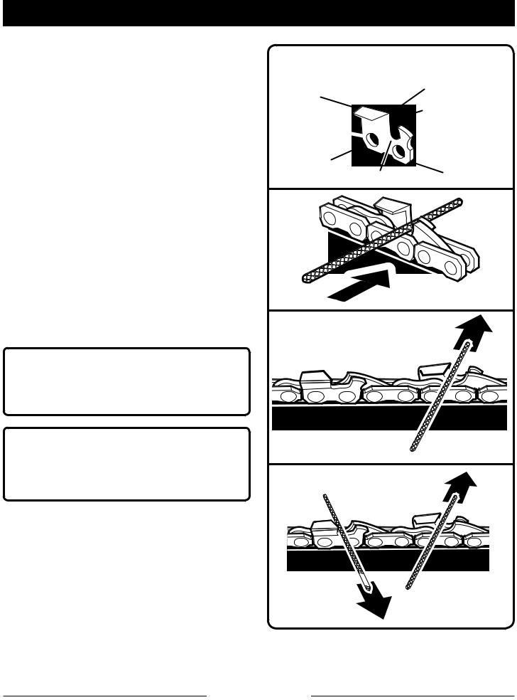
Kickback is a dangerous reaction that can lead to serious injury. Kickback may occur when the moving chain contacts an object at the upper portion of the tip of the guide bar or when the wood closes in and pinches the chain in the cut. Contact at the upper portion of the tip of the guide bar can cause the chain to dig into the object and stop the chain for an instant. The result is a lightning-fast, reverse reaction which kicks the guide bar up and back toward the operator. If the chain is pinched along the top of the guide bar, the guide bar can be driven rapidly back toward the operator, which can cause loss of control and may result in serious injury. Do not rely exclusively upon the safety devices built into the product.
With a basic understanding of kickback, you can reduce or eliminate the element of surprise. Sudden surprise contributes to accidents.
Use pole saw for cutting wood only. Do not use for cutting non-wood items.
Make sure that the area in which you are cutting is free from obstructions. Do not let the nose of the guide bar contact a log, branch, fence, or any other obstruction while you are operating the unit. Have a planned retreat path.
Do not grasp the exposed cutting blades or cutting edges when picking up or holding the product.
Cut only when visibility and light are adequate for you to see clearly.
To protect yourself from electrocution, do not operate within 50 feet of overhead electrical lines.
Before starting the motor, make sure the chain is not contacting any object.
To protect yourself from falling branches, do not stand directly under the branch or limb being cut. This unit should not be held at an angle over 60° from ground level.
Turn off the motor and make sure cutting attachment has stopped before setting unit down.
Follow the sharpening and maintenance instructions for the saw chain.
Use only the replacement guide bars and low kickback chains specified for the unit.
Do not operate the saw with one hand! Serious injury to the operator, helpers, bystanders, or any combination of these persons may results from one hand operation. This saw intended for two-handed use.
Use extreme caution when cutting small-sized brush and saplings because slender material may catch the saw chain and be whipped toward you or pull you off balance.
When cutting a limb that is under tension, be alert for spring back so that you will not be struck when the tension in the wood fibers is released.
To avoid accidental starting, never carry plugged in product with finger on switch. Be sure switch is off when plugging in.
Page 4 — English

SPECIFIC SAFETY RULES
Maintain product with care. Keep cutting edge sharp and clean for best performance and to reduce the risk of injury. Follow instructions for lubricating and changing accessories. Inspect cord periodically and, if damaged, have it repaired by an authorized service facility. Inspect extension cords periodically and replace if damaged. Keep handles dry, clean, and free from oil and grease.
Check damaged parts. Before further use of the product, a guard or other part that is damaged should be carefully checked to determine that it will operate properly and perform its intended function. Check for alignment of moving parts, binding of moving parts, breakage of parts, mounting, and any other condition that may affect its operation. A guard or other part that is damaged should be properly repaired or replaced by an authorized service center unless indicated elsewhere in this manual.
Disconnect the plug from power source when not in use, before servicing, and when changing accessories.
Service on the product must be performed by qualified repair personnel only. Service or maintenance performed by unqualified personnel could result in injury to the user or damage to the product.
If the power supply cord is damaged, it must be replaced only by the manufacturer or by an authorized service center to avoid risk.
Save these instructions. Refer to them frequently and use them to instruct others who may use this product. If you loan someone this product, loan them these instructions also to prevent misuse of the product and possible injury.
Page 5 — English
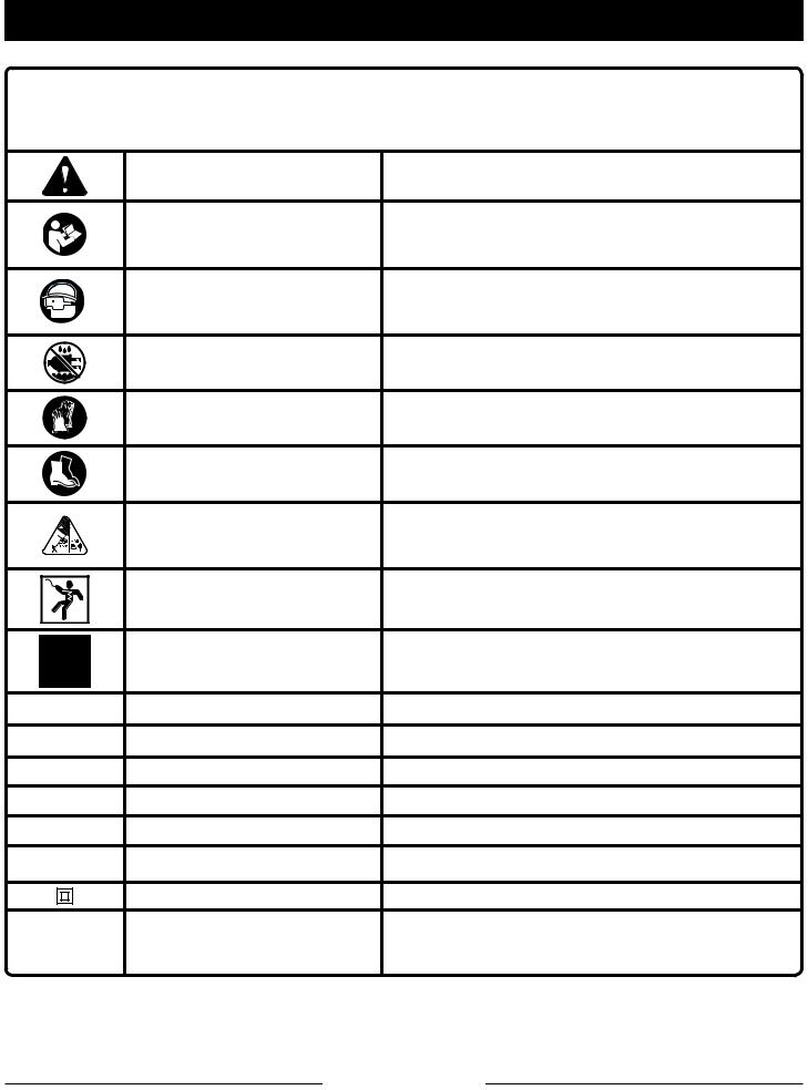
SYMBOLS
Some of the following symbols may be used on this product. Please study them and learn their meaning. Proper interpretation of these symbols will allow you to operate the product better and safer.
SYMBOL |
NAME |
EXPLANATION |
|
|
Safety Alert Symbol |
Indicates a potential personal injury hazard. |
|
|
Read the Operator’s |
To reduce the risk of injury, user must read and |
|
|
understand operator’s manual before using this |
||
|
Manual |
||
|
product. |
||
|
|
||
|
Wear Eye and Head |
Always wear eye protection with side shields |
|
|
marked to comply with ANSI Z87.1, along with |
||
|
Protection |
||
|
head protection. |
||
|
|
||
|
Wet Conditions Alert |
Do not expose to rain or use in damp locations. |
|
|
Gloves |
Wear non-slip, heavy-duty protective gloves when |
|
|
handling the pole saw and the blade. |
||
|
|
||
|
Safety Footwear |
Wear non-slip safety footwear when using this |
|
|
equipment. |
||
|
|
||
|
Keep Tool Away from Electri- |
DANGER! Risk of electrocution! Keep tool 50 feet |
|
|
cal Lines/Keep Bystanders |
away from electrical lines. Keep all bystanders at |
|
|
Away |
least 50 ft. away. |
|
|
Electric Shock |
Failure to use in dry conditions and to observe safe |
|
|
practices can result in electric shock. |
||
|
|
||
|
No Hands Symbol |
Failure to keep your hands away from the blade will |
|
|
result in serious personal injury. |
||
|
|
||
V |
Volts |
Voltage |
|
A |
Amperes |
Current |
|
Hz |
Hertz |
Frequency (cycles per second) |
|
W |
Watt |
Power |
|
hrs |
Hours |
Time |
|
no |
No Load Speed |
Rotational speed, at no load |
|
|
Class II Construction |
Double-insulated construction |
|
.../min |
Per Minute |
Revolutions, strokes, surface speed, orbits etc., |
|
per minute |
|||
|
|
Page 6 — English
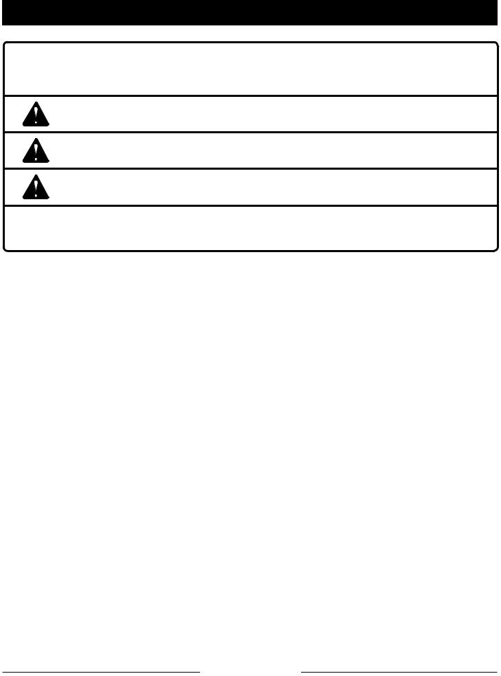
SYMBOLS
The following signal words and meanings are intended to explain the levels of risk associated with this product.
SYMBOL SIGNAL |
MEANING |
|
DANGER: |
Indicates an imminently hazardous situation, which, if not avoided, |
|
will result in death or serious injury. |
||
|
||
WARNING: |
Indicates a potentially hazardous situation, which, if not avoided, |
|
could result in death or serious injury. |
||
|
||
CAUTION: |
Indicates a potentially hazardous situation, which, if not avoided, |
|
may result in minor or moderate injury. |
||
|
(Without Safety Alert Symbol) Indicates important information not NOTICE: related to an injury hazard, such as a situation that may result in
property damage.
Page 7 — English

ELECTRICAL
DOUBLE INSULATION
Double insulation is a concept in safety in electric power tools, which eliminates the need for the usual three-wire grounded power cord. All exposed metal parts are isolated from the internal metal motor components with protecting insulation. Double insulated tools do not need to be grounded.
It is possible to tie the extension cord and power cord in a knot to prevent them from becoming disconnected during use. Make the knot as shown in figure 1, then connect the plug end of the power cord into the receptacle end of the extension cord. This method can also be used to tie two extension cords together.
WARNING:
The double insulated system is intended to protect the user from shock resulting from a break in the tool’s internal insulation. Observe all normal safety precautions to avoid electrical shock.
NOTE: Servicing of a product with double insulation requires extreme care and knowledge of the system and should be performed only by a qualified service technician. For service, we suggest you return the product to your nearest authorized service center for repair. Always use original factory replacement parts when servicing.
ELECTRICAL CONNECTION
This product has a precision-built electric motor. It should be connected to a power supply that is 120 volts, AC only (normal household current), 60 Hz.
Do not operate this product on direct current (DC). A substantial voltage drop will cause a loss of power and the motor will overheat. If the product does not operate when plugged into an outlet, double-check the power supply.
EXTENSION CORDS
See Figure 1.
When using a power tool at a considerable distance from a power source, be sure to use an extension cord that has the capacity to handle the current the product will draw. An undersized cord will cause a drop in line voltage, resulting in overheating and loss of power. Use the chart to determine the minimum wire size required in an extension cord. Only round jacketed cords listed by Underwriter’s Laboratories (UL) should be used.
When working outdoors with a product, use an extension cord that is designed for outside use. This type of cord is designated with “W-A” or “W” on the cord’s jacket.
Before using any extension cord, inspect it for loose or exposed wires and cut or worn insulation.
A proper extension cord is available at an authorized service center.
|
|
|
|
|
|
Fig. 1 |
|
|
|
|
|||
**Ampere rating (on product data plate) |
|
|
|
|||
|
0-2.0 |
2.1-3.4 3.5-5.0 |
5.1-7.0 |
7.1-12.0 |
12.1-16.0 |
|
Cord Length |
|
Wire Size (A.W.G.) |
|
|
||
|
|
|
|
|
|
|
25' |
16 |
16 |
16 |
16 |
14 |
14 |
|
|
|
|
|
|
|
50' |
16 |
16 |
16 |
14 |
14 |
12 |
|
|
|
|
|
|
|
100' |
16 |
16 |
14 |
12 |
10 |
— |
**Used on 12 gauge - 20 amp circuit.
NOTE: AWG = American Wire Gauge
WARNING:
Keep the extension cord clear of the working area. Position the cord so that it will not get caught on lumber, tools, or other obstructions while you are working with a power tool. Failure to do so can result in serious personal injury.
WARNING:
Check extension cords before each use. If damaged replace immediately. Never use the product with a damaged cord since touching the damaged area could cause electrical shock resulting in serious injury.
Page 8 — English
|
FEATURES |
PRODUCT SPECIFICATIONS |
|
Bar Length....................................................................................................................................... |
8 in. |
Cutting Capacity.............................................................................................................................. |
6 in. |
Chain Pitch..................................................................................................................................... |
3/8 in. |
Chain Type...................................................................................... |
Low Profile Skip Tooth Narrow Kerf |
Input........................................................................................................ |
120 V, AC only, 60 Hz, 6 Amps |
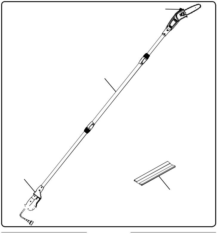
OIL CAP |
TELESCOPING
POLE
LOCK-OUT
BUTTON
SCABBARD


 CORD
CORD
RETAINER
Fig. 2
Page 9 — English

FEATURES
KNOW YOUR POLE SAW
See Figure 2.
The safe use of this product requires an understanding of the information on the product and in this operator’s manual as well as a knowledge of the project you are attempting. Before use of this product, familiarize yourself with all operating features and safety rules.
CORD RETAINER
A convenient cord retainer helps keep the extension cord connection secure during tool operation.
LOCK-OUT BUTTON
To help prevent accidental starting, the lock-out button must be depressed along with the switch trigger.
QUICK-VIEW OIL INDICATOR
Semi-transparent bar lube reservoir that allows user to see when to add lubricant.
SCABBARD
The scabbard keeps the operator from coming in contact with the sharp blades when the tool is not in use. It also helps keep the blades from being nicked or damaged when the tool is in storage.
TELESCOPING POLE
The pole can be adjusted to different lengths for ease of use.
ASSEMBLY
UNPACKING
This product requires assembly.
nCarefully remove the product and any accessories from the box. Make sure that all items listed in the packing list are included.
 WARNING:
Do not use this product if any parts on the Packing List are already assembled to your product when you unpack it. Parts on this list are not assembled to the product by the manufacturer and require customer installation. Use of a product that may have been improperly assembled could result in serious personal injury.
nInspect the product carefully to make sure no breakage or damage occurred during shipping .
nDo not discard the packing material until you have carefully inspected and satisfactorily operated the product.
nIf any parts are damaged or missing, please call 1-800-860-4050 for assistance.
PACKING LIST
Pole Saw
Scabbard
Operator’s Manual
 WARNING:
If any parts are damaged or missing, do not operate this product until the parts are replaced. Use of this product with damaged or missing parts could result in serious personal injury.
 WARNING:
Do not attempt to modify this product or create accessories not recommended for use with this product. Any such alteration or modification is misuse and could result in a hazardous condition leading to possible serious personal injury.
 WARNING:
Do not connect to power supply until assembly is complete. Failure to comply could result in accidental starting and possible serious personal injury.
Page 10 — English
ASSEMBLY
LOWER
COLLAR
BUTTON
HANDLE
POLE
THREADED BASE |
|
|
BUTTON |
INTERMEDIATE |
THREADED |
POLE |
BASE |
|
CORD |
|
|
UPPER |
POWERHEAD |
COLLAR |
POLE |
Fig. 3
CONNECTING THE POLES
See Figure 3.
Before using the pole saw, a one-time assembly is required. When removed from the box, the three poles are connected by an electrical cord as shown above.
nRemove the four (4) rubber cord protectors from inside the poles. This material protects the cord during shipping and MUST be discarded immediately.
nUnscrew the lower collar from the threaded base on the intermediate pole and push back over the cord to the handle pole shaft as shown.
nInsert the handle pole into the intermediate pole and slide together until you hear the button click. The tubes are egg-shaped and will only install one way.
nLower the collar on the handle pole to the threaded base on the intermediate pole and rotate clockwise to secure.
nRepeat this process to attach the intermediate pole to the powerhead pole.
NOTE: Once assembled correctly, handle pole and powerhead pole should not be able to separate from intermediate pole when pulled. Repeat above steps if poles can be separated from intermediate pole.
WARNING:
Failure to lock powerhead pole as directed above could result in serious injury or death.
Page 11 — English
OPERATION
 DANGER:
Never cut near power lines, electric cords, or other electric sources. If bar and chain jams on any electrical cord or line, DO NOT TOUCH THE BAR OR CHAIN! THEY CAN BECOME ELECTRICALLY LIVE AND VERY DANGEROUS. Continue to hold the pole saw by the insulated rear handle or lay it down and away from you in a safe manner. Disconnect the electrical service to the damaged line or cord before attempting to free the bar and chain from the line or cord. Contact with the bar, chain, other conductive parts of the pole saw, or live electric cords or lines will result in death by electrocution, electric shock, or serious personal injury.
 WARNING:
Do not allow familiarity with this product to make you careless. Remember that a careless fraction of a second is sufficient to inflict serious injury.
 WARNING:
Always wear eye protection with side shields marked to comply with ANSI Z87.1, along with head protection. Failure to do so could result in objects being thrown into your eyes and other possible serious injuries.
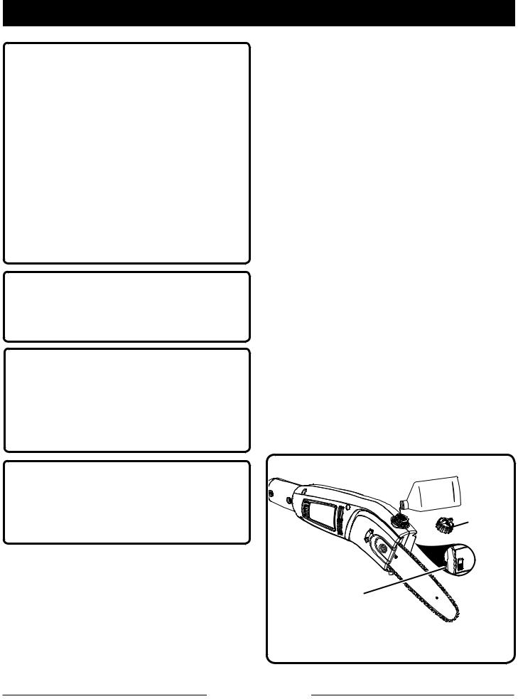
ADDING BAR AND CHAIN LUBRICANT
See Figure 4
Use Bar and Chain Lubricant. It is designed for chains and chain oilers, and is formulated to perform over a wide temperature range with no dilution required.
NOTE: Pole saw comes from the factory with no bar and chain oil added. Level should also be checked after every 20 minutes of use and refilled as needed.
nDisconnect the pole saw from the power supply.
nRemove oil cap.
nCarefully pour the bar and chain oil into the tank.
nWipe off excess oil.
nCheck and fill the oil tank when quick view oil indicator is below the second to last indicator line.
nRepeat as needed.
NOTE: Do not use dirty, used or otherwise contaminated oils. Damage may occur to the bar or chain.
NOTE: It is normal for oil to seep from the saw when not in use. To prevent seepage, empty the oil tank after each use then run for one minute. When storing the unit for a long period of time (three months or longer) be sure the chain is lightly lubricated; this will prevent rust on the chain and bar sprocket.
 WARNING:
Do not use any attachments or accessories not recommended by the manufacturer of this product. The use of attachments or accessories not recommended can result in serious personal injury.
APPLICATIONS
You may use this product for the purposes listed below:
nLimbing
nPruning
CHAIN |
|
LUBRICANT |
OIL |
|
|
|
RESERVOIR |
|
CAP |
QUICK VIEW |
OIL INDICATOR |
Fig. 4
Page 12 — English
OPERATION
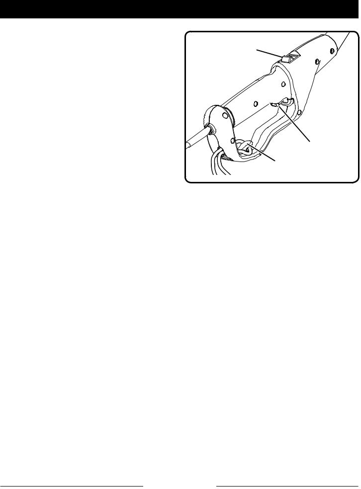
CONNECTING TO POWER SUPPLY
See Figure 5.
This product is designed with a cord retainer that prevents the extension cord from being pulled loose while using.
nForm a loop with the end of the extension cord.
nInsert loop portion of extension cord through opening in the bottom of the rear handle and place over cord retainer.
nSlowly pull loop against cord retainer until the slack is removed .
nPlug product into extension cord.
NOTE: Failure to remove all excess cord slack from extension cord retainer could result in plug loosening from receptacle.
STARTING AND STOPPING
See Figure 5.
To start the motor:
n Connect the pole saw to power supply.
n Place your thumb on the lock-out button and pull it completely towards you.
n Fully depress the switch trigger.
To stop the motor:
n Release the switch trigger.
LOCK-OUT
BUTTON
SWITCH TRIGGER
CORD RETAINER
Fig. 5
ADJUSTING TELESCOPING POLE
See Figure 6.
nDisconnect the pole saw from the power supply.
nRotate the collar counterclockwise to loosen.
n Push poles towards each other to shorten the pole or pull away from each other to lengthen the pole.
NOTE: Extend the pole only to the length required to reach the limb being cut. Do not extend the handle above waist height.
n When the desired length is achieved, rotate the collar clockwise to secure.
NOTE: Adjust hand placement on the shaft of the pole saw to keep proper balance. Do not attempt to use the pole saw at a length which does not allow you to achieve proper footing and balance at all times.
Page 13 — English

OPERATION
PREPARATION FOR CUTTING
See Figures 7 - 8.
nWear non-slip gloves for maximum grip and protection.
n Maintain a proper grip on the unit whenever the motor is running. Use your right hand to firmly grip the rear handle while your left hand has a firm grip on the pole shaft.
n Hold unit firmly with both hands. Always keep your left hand on the pole shaft and your right hand on the rear handle, so your body is to the left of the chain line. Never use a left-handed (cross-handed) grip, or any stance that places your body or arm across the chain line.
n Never stand directly under the limb you are cutting.
nBe certain the collars are fully tightened before operating equipment; check them periodically for tightness during use to avoid serious injury.
BASIC CUTTING PROCEDURE
Follow the steps below to prevent damage to tree or shrub bark. Do not use a back-and-forth sawing motion.
nMake a shallow first cut (1/4 of limb diameter) on the underside of the limb close to the main limb or trunk.
nMake a second cut from the top side of the limb outboard from the first cut. Continue the cut through the limb until the limb separates from the tree. Be prepared to balance the weight of the tool when the limb falls.
nMake a final cut close to trunk.
NOTE: For second and final cuts (from top of limb or branch), hold front cutting guide against the limb being cut. This will help steady the limb and make it easier to cut. Allow chain to cut for you; exert only light downward pressure. If you force the cut, damage to the bar, chain, or motor can result.
nRelease the trigger as soon as the cut is completed.
COLLAR
Fig. 6
LOAD SECOND CUT
FIRST CUT  1/4 DIAMETER
FINAL
CUT
Fig. 7
CUTTING GUIDE |
Fig. 8 |
|
Failure to follow proper cutting procedures will result in the bar and chain binding and becoming pinched or trapped in the limb. If this should happen:
nStop the motor and disconnect from power supply.
nIf the limb can be reached from the ground, lift the limb while holding the saw. This should release the “pinch” and free the saw.
nIf the saw is still trapped, call a professional for assistance.
Page 14 — English
OPERATION
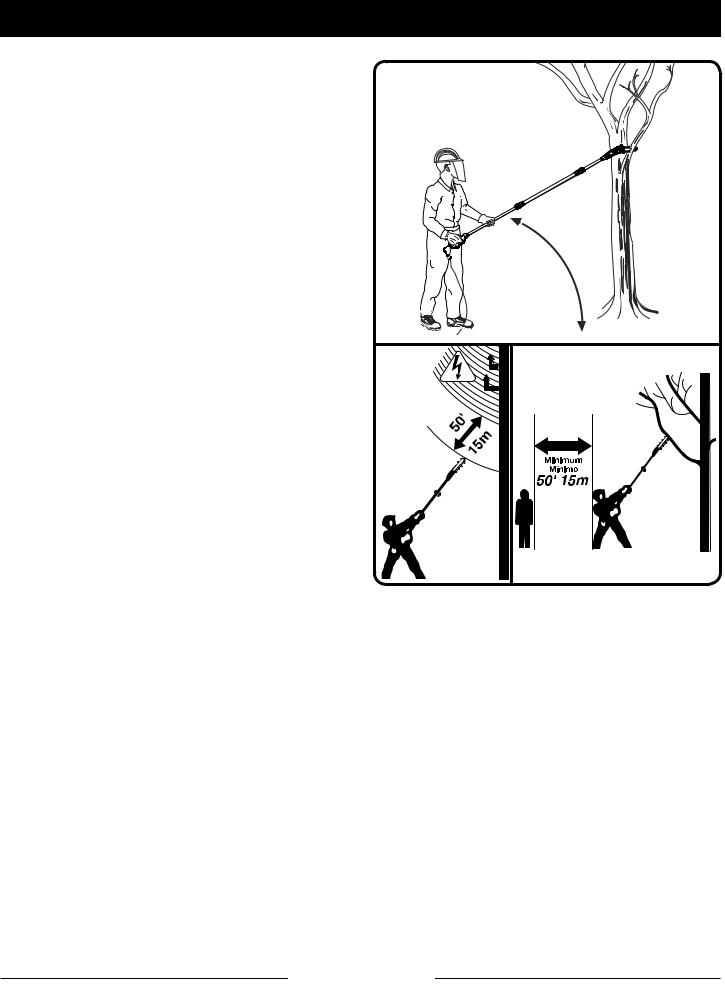
LIMBING AND PRUNING
See Figures 9 - 10.
This unit is designed for trimming small branches and limbs up to 6 in. in diameter. For best results, observe the following precautions.
n Plan the cut carefully. Be aware of the direction in which the branch will fall.
n Branches may fall in unexpected directions. Do not stand directly under the branch being cut.
n The most typical cutting application is to posi- |
|
|
tion the unit at an angle of 60° or less, depend- |
60° MAXIMUM |
|
ing on the specific situation, as shown. As the |
||
|
||
angle of the pole saw shaft to ground increases, |
|
|
the difficulty of making the first cut (from the |
Fig. 9 |
|
underside of limb) increases. |
|
n Remove long branches in several stages.
n Cut lower branches first to allow the top branches more room to fall.
n Work slowly, keeping both hands on the saw with a firm grip. Maintain secure footing and balance.
n Keep the tree between you and the chain while limbing. Cut from side of tree opposite branch you are cutting.
n Do not cut from a ladder; this is extremely |
Fig. 10 |
|
dangerous. Leave this operation for profes- |
||
|
||
sionals. |
|
n Do not make the flush cut next to the main limb or trunk until you have cut off the limb further out to reduce the weight. Following proper cutting procedures will prevent stripping the bark from the main member.
n Do not use the pole saw for felling or bucking.
n To prevent electrocution, do not operate within 50 ft. of overhead electrical lines.
n Keep bystanders at least 50 ft. away.
Page 15 — English
MAINTENANCE
WARNING:
When servicing, use only identical replacement parts. Use of any other parts could create a hazard or cause product damage.
 WARNING:
Always wear eye protection with side shields marked to comply with ANSI Z87.1, along with head protection. Failure to do so could result in objects being thrown into your eyes and other possible serious injuries.
 WARNING:
Before inspecting, cleaning or servicing the unit, stop the motor, wait for all moving parts to stop, and disconnect from power supply. Failure to follow these instructions can result in serious personal injury or property damage.
FLATS
Fig. 11
APPROX .050 in. |
|
Fig. 12 |
|
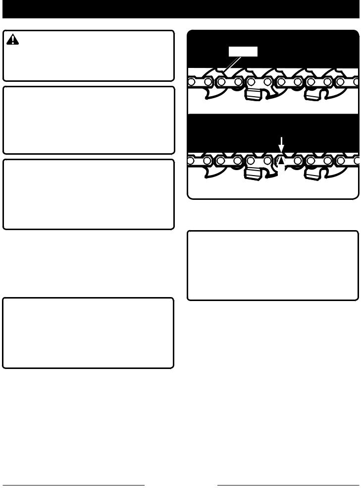
CHAIN TENSION
See Figures 11 - 12.
GENERAL MAINTENANCE
Avoid using solvents when cleaning plastic parts. Most plastics are susceptible to damage from various types of commercial solvents and may be damaged by their use. Use clean cloths to remove dirt, dust, oil, grease, etc.
 WARNING:
Do not at any time let brake fluids, gasoline, petroleum-based products, penetrating oils, etc., come in contact with plastic parts. Chemicals can damage, weaken, or destroy plastic, which could result in serious personal injury.
All chain saw service, other than the items listed in the instruction manual maintenance instructions, should be performed by competent chain saw service personnel. (For example, if improper tool is used to hold the flywheel in order to remove the clutch, structural damage to the flywheel could occur and subsequently could cause the flywheel to burst).
 WARNING:
To avoid possible serious injury, never touch or adjust the chain while the motor is running. The saw chain is very sharp; always wear protective gloves when performing maintenance to the chain.
nStop the motor and disconnect from power supply before setting the chain tension. Make sure the chain cover screw is loose to finger tight, turn the chain tensioning screw clockwise to tension the chain. Refer to Replacing the Bar and Chain for additional information.
NOTE: A cold chain is correctly tensioned when there is no slack on the underside of the guide bar, the chain is snug, but it can be turned by hand without binding.
nChain must be re-tensioned whenever the flats on the drive links hang out of the bar groove as shown in fig. 11.
nDuring normal operation, the temperature of the chain will increase. The drive links of a correctly tensioned warm chain will hang approximately
.050 in. out of the bar groove, as shown in fig. 12.
Page 16 — English

MAINTENANCE
NOTE: New chain tends to stretch; check chain tension frequently and tension as required.
NOTICE:
Chain tensioned while warm, can be too tight upon cooling. Check the “cold tension” before next use.
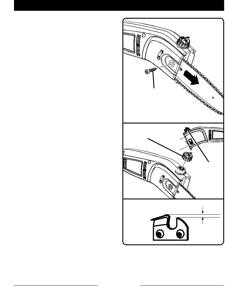
REPLACING THE BAR AND CHAIN
See Figures 13 - 16.
 WARNING:
To avoid possible serious injury, stop the motor and disconnect from power supply before replacing the bar, chain, or performing any maintenance operation.
nRemove the chain cover screw and chain cover.
nThe bar contains a bar stud slot that fits over the bar stud. The bar also contains a chain tensioning pin hole which fits over the chain tensioning pin.
nPlace the bar onto the bar stud so that the chain tensioning pin fits into the chain tensioning pin hole.
nFit the chain over the sprocket and into the bar groove. The cutters on the top of the bar should face toward the bar tip, in the direction of the chain rotation.
nReplace the chain cover and install the chain cover screw. Tighten the screw finger tight only. The bar must be free to move for tension adjustment.
nRemove all slack from chain by turning the chain tensioning screw clockwise, assuring that the chain seats into the bar groove during tensioning.
nLift the tip of the bar up to check for sag. Release the tip of the bar, and turn the chain tensioning screw 1/2 turn clockwise. Repeat this process until sag does not exist.
nHold the tip of the bar up and tighten the chain cover screw securely.
nChain is correctly tensioned when there is no slack on the underside of the bar, the chain is snug, but it can be turned by hand without binding.
CHAIN |
CHAIN |
COVER |
BAR |
CHAIN COVER SCREW Fig. 13 |
|
SPROCKET |
CHAIN |
TENSIONING PIN |
|
CHAIN


COVER
BAR
STUD
|
|
BAR |
CHAIN |
CHAIN |
|
TENSIONING |
|
|
COVER |
PIN HOLE |
BAR STUD |
SCREW |
|
SLOT |
Fig. 14
CHAIN
ROTATION
SPROCKET |
CHAIN |
|


 CHAIN TENSIONING SCREW
Fig. 15
NOTE: If chain is too tight, it will not rotate. Loosen the chain cover screw slightly and turn adjusting screw 1/4 turn counterclockwise. Lift the tip of the bar up and retighten chain cover screw.
Page 17 — English
MAINTENANCE
CHAIN OILER
See Figure 17.
Use Premium Bar and Chain Lubricant. It is designed for chains and chain oilers and is formulated to perform over a wide temperature range with no dilution required.
nStop the motor and disconnect from power supply.
nRemove the cap and carefully pour approximately 2 oz. of bar and chain lubricant into the bar lube reservoir.
nReplace the cap and tighten securely.
nCheck and refill the bar lube reservoir every time the pole saw is used.
NOTE: Do not use dirty, used, or otherwise contaminated lubricants. Damage may occur to the oil pump, bar, or chain.
CHAIN MAINTENANCE
See Figure 18.
For smooth and fast cutting, the chain needs to be maintained properly. The following conditions indicate that the chain requires sharpening:
nWood chips are small and powdery
nChain must be forced through the wood during cutting
nChain cuts to one side
During maintenance of the chain, consider the following:
nImproper filing angle of the side plate can increase the risk of a severe kickback.
nDepth gauge (or raker clearance) setting determines the height the cutter enters the wood and the size of the wood chip that is removed. Too much clearance increases the potential for kickback. Too little clearance decreases the size of the wood chip thus decreasing the chain's cutting ability.
nIf cutter teeth have hit hard objects such as nails and stones, or have been abraded by mud or sand on the wood, have service dealer sharpen chain.
CHAIN
COVER
SCREW
Fig. 16
REMOVE
CAP
BAR LUBE


 RESERVOIR
Fig. 17
RAKER (DEPTH GAUGE)
CLEARANCE
.025 in.
Fig. 18
Page 18 — English
MAINTENANCE
HOW TO SHARPEN THE CUTTERS
See Figures 19 - 22.
Be careful to file all cutters to the specified angles and to the same length, as fast cutting can be obtained only when all cutters are uniform.
nStop the motor and disconnect from power supply.
nTighten the chain tension enough that the chain does not wobble. Do all of your filing at the midpoint of the bar. Wear gloves for protection.
nUse a 5/32 in. diameter round file and holder.
nKeep the file level with the top plate of the tooth. Do not let the file dip or rock.
nUsing light but firm pressure, stroke towards the front corner of the tooth. Lift file away from the steel on each return stroke.
nPut a few firm strokes on every tooth. File all left hand cutters in one direction. Then move to the other side and file the right hand cutters in the opposite direction. Occasionally remove filings from the file with a wire brush.
NOTICE:
Dull or improperly sharpened chain can cause excessive motor speed during cutting which may result in severe motor damage.
 WARNING:
Improper chain sharpening increases the potential of kickback. Failure to replace or repair damaged chain can cause serious injury.
PARTS OF A CUTTER
CUTTING TOP CORNER PLATE
SIDE PLATE RIVET HOLE 

 DEPTH GAUGE
HEEL |
TOE Fig. 19 |
GULLET |
Fig. 20
Fig. 21
LEFT HAND
CUTTERS
RIGHT HAND 


CUTTERS
Fig. 22
Page 19 — English
MAINTENANCE
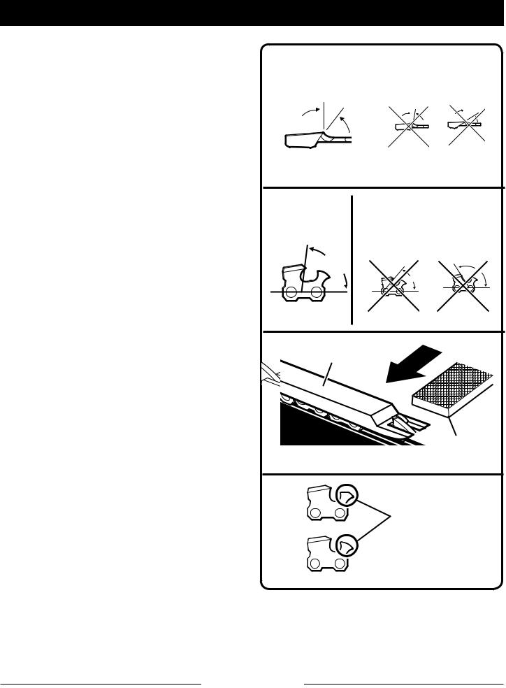
TOP PLATE FILING ANGLE
See Figure 23.
CORRECT 30° - File holders are marked with guide marks to align file properly to produce correct top plate angle.
LESS THAN 30° - For Cross Cutting.
MORE THAN 30° - Feathered Edge Dulls Quickly.
SIDE PLATE ANGLE
See Figure 24.
CORRECT - 80° Produced automatically if correct diameter file is used in file holder.
HOOK - “Grabs” and dulls quickly. Increases potential of KICKBACK.
Results from using a file with diameter too small, or file held too low.
BACKWARD SLOPE - Needs too much feed pressure, causes excessive wear to bar and chain.
Results from using a file with diameter too large, or file held too high.
DEPTH GAUGE CLEARANCE
See Figures 25 - 26.
The depth gauge should be maintained at a clearance of .025 in. Use a depth gauge tool for checking the depth gauge clearances.
Every time the chain is filed, check the depth gauge clearance.
Use a flat file and a depth gauge jointer to lower all gauges uniformly. Depth gauge jointers are available in .020 in. to .035 in. Use a .025 in. depth gauge jointer. After lowering each depth gauge, restore original shape by rounding the front. Be careful not to damage adjoining drive links with the edge of the file.
Depth gauges must be adjusted with the flat file in the same direction the adjoining cutter was filed with the round file. Use care not to contact cutter face with flat file when adjusting depth gauges.
CORRECT TOP PLATE |
INCORRECT TOP PLATE |
|||
FILING ANGLE |
FILING ANGLE |
|||
|
LESS |
MORE |
||
30° |
THAN 30° |
THAN 30° |
||
|
|
|
|
|
|
|
|
|
|
|
|
|
|
|
|
|
Fig. 23 |
CORRECT SIDE |
INCORRECT SIDE PLATE |
|
PLATE FILING |
FILING ANGLE |
|
ANGLE |
HOOK |
|
|
BACKWARD |
|
|
|
SLOPE |
80° |
|
|
Fig. 24
DEPTH GAUGE
JOINTER
 FLAT FILE
Fig. 25
RESTORE ORIGINAL
SHAPE BY
ROUNDING THE
FRONT
Fig. 26
Page 20 — English
MAINTENANCE
GUIDE BAR MAINTENANCE
When the guide bar shows signs of wear, reverse it on the saw to distribute the wear for maximum bar life. The bar should be cleaned every day of use and checked for wear and damage.
Feathering or burring of the bar rails is a normal process of bar wear. Such faults should be smoothed with a file as soon as they occur.
A bar with any of the following faults should be replaced.
Wear inside the bar rails which permits the chain to lay over sideways.
Bent guide bar.
Cracked or broken rails.
Spread rails.
Lubricate guide bars with a sprocket at their tip weekly. Using a grease syringe, lubricate weekly in the lubricating hole. Turn the guide bar and check that the lubrication holes and chain groove are free from impurities.
STORING THE PRODUCT
See Figure 27.
Clean all foreign material from the product. Store idle unit indoors in a dry, well-ventilated area that is inaccessible to children. Keep away from corrosive agents such as garden chemicals and de-icing salts.
n Always place the scabbard on the saw bar when transporting or storing the pole saw. The scabbard is a snug fit and must be attached very carefully due to the sharp teeth on the saw chain. This is best done by grasping the scabbard at one end, in the center portion of the scabbard, and carefully sliding it over the chain as shown. Use caution to avoid the sharp teeth of the chain.
NOTE: The saw chain is very sharp. Always wear protective gloves when handling the chain.
SCABBARD
Fig. 27
Page 21 — English
 Loading...