


PD-2070VR
PD-2070VR
C
PD-2080VR
PERCEUSE A PERCUSSION
IMPACT DRILL
SCHLAGBOHRMASCHINE
TALADRO DE PERCUSIÓN
TRAP ANO A PERCUSSIONE
BERBEQUIM DE PERCUSSAO
KLOPBOOR
SLAGBORRMASKIN
SLAGBOR
SLAGDRILL
ISKUPORAKONE
KP√Y™TIK√ §P∞¶∞¡√
6984382(RL)
MANUEL D’UTILISATION
OWNER’S OPERATING MANUAL
BENUTZERHANDBUCH
MANUAL DEL USUARIO
MANUALE DI UTILIZZAZIONE
MANUAL DE UTILIZAÇÃO
GEBRUIKSAANWIJZING
ÄGARENS HANDBOK
BETJENINGSVEJLEDNING
BRUKSANVISNING
KÄYTTÖOHJE
√¢∏°IE™XPH™Eø™
E
09-02
PD-2070VR
2
1
3
6
8
7
10
11
1
9
PD-2070VR
4
5
7
11
PD-2070VR
6
4
5
2
15
3
17
PD-2080VR
1
16
2
12
3
4
5
13
14
678
8
A
B
9
910 11

MERCI D’AVOIR ACHETÉ UN OUTIL RYOBI.
Pour garantir votre sécurité, et obtenir toute satisfaction, lisez
attentivement CE MANUEL D’UTILISATION et les CONSIGNES DE
SÉCURITÉ qu’il contient avant d’utiliser l’appareil.
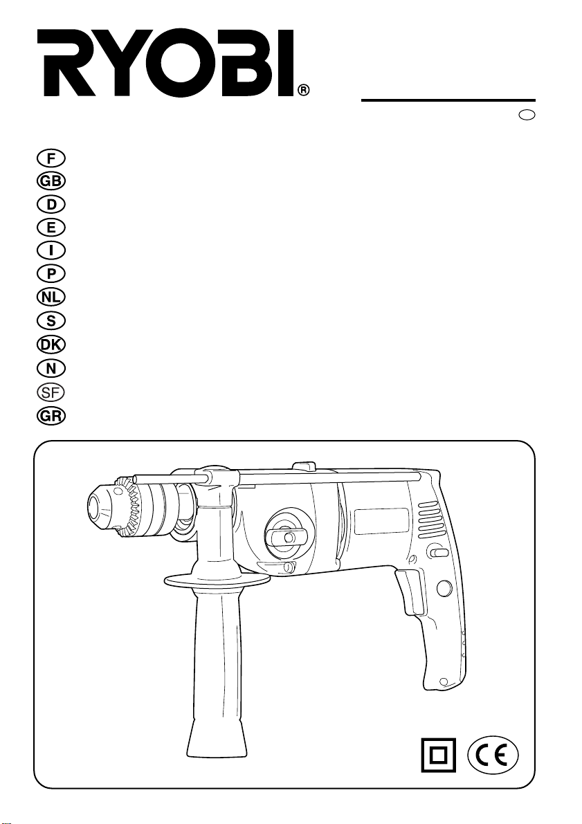
DESCRIPTION
1. Mandrin 10. Fentes d’aération
2. Clé du mandrin 11. Bouton de rotation à gauche
3. Mèche 12. Bouton de rotation à droite
4. Interrupteur 13. Pièce à travailler
5. Bouton de verrouillage 14. Cale de bois
6. Bouton de réglage des vitesses 15. Mandrin
7. Bouton de changement 16. Bague
de mode de perçage 17. Manchon
8. Butée de profondeur
9. Poignée auxiliaire
RÈGLES DE MANIPULATION
1. Assurez-vous que l’outil est bien branché sur une alimentation dont
le voltage correspond à celui indiqué sur la plaque signalétique.
2. N’utilisez jamais l’outil si le capot de protection ou des écrous sont
manquants. Si tel est le cas, prenez soin de les remettre en place
avant toute utilisation. Assurez-vous que toutes les pièces sont toujours
en parfait état de fonctionnement.
3. Arrimez toujours vos outils lorsque vous travaillez en hauteur.
4. Ne touchez jamais la lame, la mèche, la meule ou toute autre pièce
en rotation durant l’utilisation.
5. Ne faites jamais démarrer un outil lorsque son élément de rotation
est en contact avec la pièce à travailler.
6. Ne reposez jamais l’outil avant l’arrêt total de toutes les pièces en
rotation.
7. ACCESSOIRES : l’utilisation d’accessoires ou d’équipements autres
que ceux recommandés dans ce manuel peut présenter un risque.
8. PIECES DÉTACHÉES : utilisez uniquement des pièces détachées
identiques en cas de réparation.
CONSIGNES DE SÉCURITÉ CONCERNANT LA
PERCEUSE À PERCUSSION
1. Assurez-vous que la mèche est correctement montée. Une mèche
montée de façon incorrecte est extrêmement dangereuse car elle peut
voler ou se casser durant le perçage.
2. Ne portez ni gants ni cravate car ceux-ci pourraient être pris dans une
mèche en rotation.
3. Tenez l’outil solidement à deux mains afin d’éviter des risques
d’accidents ou de blessures.
4. Ne touchez jamais le mandrin ni les parties en métal lors du perçage
de murs, sols ou autres surfaces recouvrant des fils électriques. Ne
tenez l’outil que par la poignée en plastique afin d’éviter tout risque
d’électrocution.
5. En cours d’utilisation, la pièce à travailler doit être solidement
maintenue par une pince-étau ou une bride de fixation etc. afin d’éviter
qu’elle ne bouge sous l’effet de rotation du mandrin.
CARACTÉRISTIQUES
Capacité du mandrin 13 mm 13 mm
Capacité de perçage
bois 40 mm 40 mm
étal 13 mm 13 mm
béton 20 mm 20 mm
Fréquence 50 Hz 50 Hz
Voltage* 110 V, 230 V 110 V, 230V
Puissance 710 W 710 W
Vitesse à vide
maxi 0-2.700 min.
mini 0-1.250 min.-10-1.250 min.
Coups par minute
maxi 0-43.200 min.
mini 0-20.000 min.-10-20.000 min.
Longueur totale 365 mm 371 mm
Poids net 2,4 kg 2,6 kg
*Veillez à vérifier la plaque signalétique du produit, car celle-ci peut
être différente selon les pays.
PD-2070VR PD-2080VR
-1
0-2.700 min.
-1
0-43.200 min.
-1
-1
-1
-1
ACCESSOIRES STANDARD
Poignée auxiliaire, butée de profondeur, clé du mandrin (PD-2070VR
uniquement)
APPLICATIONS
(L’outil ne doit être utilisé qu’aux fins suivantes.)
1. Perçage de surfaces en bois, métal et plastique.
2. Perçage de béton (perçage à percussion uniquement).
NUISANCES SONORES
Le bruit (niveau d’intensité sonore) dans l’atelier peut dépasser les 85 dB
(A). Dans ce cas, des mesures d’isolation acoustique ou de protection contre
le bruit doivent être prises par l’opérateur.
(HE08)
MONTAGE ET DÉMONTAGE DE LA MÈCHE (Fig.
1, 2)
VEILLEZ À DÉBRANCHER L’APPAREIL DE LA PRISE ÉLECTRIQUE
AVANT DE MONTER ET DE DÉMONTER LA MÈCHE.
(PD-2070VR) (Fig. 1)
1. Insérez la mèche (3) dans le mandrin (1) aussi loin que possible.
2. Serrez ensuite le mandrin à l’aide de la clé à mandrin (2) fournie.
(Il y a trois orifices dans le mandrin. Insérez la clé à mandrin dans
chaque orifice l’un après l’autre et serrez sans à-coups dans la
direction A.)
3. Pour retirer la mèche, insérez la clé à mandrin dans chacun des trois
orifices et tournez dans la direction B.
(PD-2080VR) (Fig. 2)
(Montage)
1. Pour dessérer le mandrin (15), maintenez fermement la bague (16)
et tournez-le (17) dans la direction A.
2. Insérez la mèche (3) bien à fond dans le mandrin.
3. Maintenez fermement la bague et tournez le mandrin dans la direction
B jusqu’à ce que vous entendiez un clic.
4. Continuez ensuite à serrer le mandrin.
(Démontage)
1. Maintenez fermement la bague et tournez le mandrin dans la direction
A.
2. Après avoir desséré le mandrin, retirez la mèche.
INTERRUPTEUR (Fig. 3)
Votre perceuse se met en marche et s’arrête lorsque vous appuyez ou
relâchez l’interrupteur (4).
La vitesse est réglable de 0 à 2.700 min.
-1
1.250 min.
Dans le cadre d’une utilisation continue, appuyez sur le bouton de
verrouillage (5) tout en appuyant sur l’interrupteur. Appuyez de nouveau
pour déverrouiller le bouton.
en mode lent selon la pression exercée sur l’ interrupteur.
-1
en mode rapide, et de 0 à
CHANGEMENT DE LA DIRECTION DE ROTATION
(Fig. 3, 4)
Pour modifier la direction de rotation, arrêtez l’outil et enfoncez le bouton
avant (12) ou le bouton arrière (11).
Lorsque le bouton avant est enfoncé, la mèche tourne dans le sens des
aiguilles d’une montre si vous la visualisez depuis l’extrémité de la poignée
de l’outil.
Lorsque le bouton arrière est enfoncé, la mèche tourne dans le sens inverse
des aiguilles d’une montre.
MODIFICATION DE LA VITESSE DE ROTATION
(Fig. 5)
La vitesse de rotation ne peut être modifiée qu’une fois l’outil arrêté.
Le bouton de réglage de la vitesse (6) est situé du côté gauche du capot de
protection.
Lorsque le bouton est en position “1”, l’outil est en vitesse minimum.
Lorsque le bouton est en position “2”, l’outil est en vitesse maximum.

PASSAGE ENTRE LES MODES PERÇAGE ET
PERÇAGE À PERCUSSION (Fig. 6)
Le bouton de changement de mode de perçage (7) est situé sur le dessus
de l’outil. Il permet de passer du mode perçage standard au mode perçage
à percussion et inversément.
MODE PERÇAGE : Déplacez le bouton sur le symbole “ ” pour obtenir
une rotation sans percussion.
MODE PERÇAGE À PERCUSSION : Déplacez le bouton sur le symbole
“ ” pour obtenir un perçage à percussion.
FONCTIONNEMENT
NE RECOUVREZ JAMAIS LES FENTES D’AÉRATION (10) CAR ELLES
DOIVENT TOUJOURS RESTER OUVERTES POUR ASSURER UNE
VENTILATION ADÉQUATE DU MOTEUR.
PERÇAGE DU BOIS (Fig. 7, 8)
Afin d’éviter la présence de fentes disgracieuses autour du trou alésé sur
l’autre face de la pièce, placez une cale de bois sous la pièce à travailler.
PERÇAGE DU MÉTAL (Fig. 9)
Les métaux tels qu’acier/laiton, aluminum et acier inoxidable, ainsi que les
tuyaux peuvent aussi être percés. Repérez l’endroit à percer à l’aide d’une
pointe ou d’un poinçon.
PERÇAGE DU BÉTON (Fig. 10)
Les roches et le béton sont généralement percés en mode percussion.
Lors du perçage de matériaux délicats tels que du carrelage, il est
indispensable de commencer par le perçage standard, puis une fois le
carrelage percé, de poursuivre par le perçage à percussion.
Lorsque les trous alésés sont profonds, il est conseillé de retirer
régulièrement la mèche afin d’extraire poussières et débris du trou.
POIGNÉE AUXILIAIRE ET BUTÉE DE
PROFONDEUR (Fig. 11)
POIGNÉE AUXILIAIRE
La poignée auxiliaire (9) peut subir une rotation de 360°.
Desserrez la poignée en la tournant dans la direction A, et serrez-la dans
une position commode en la tournant dans la direction B.
BUTÉE DE PROFONDEUR
En fixant une butée de profondeur (8), les trous d’une profondeur fixe peuvent
être percés avec précision.
La profondeur du trou sera égale à la distance entre l’extrémité de la mèche
et celle de la butée de profondeur.
En tournant la poignée dans la direction A, la butée de profondeur peut être
libérée et la profondeur réglée. Une fois la profondeur réglée, fixez à nouveau
la butée de profondeur en tournant la poignée dans la direction B.
ENTRETIEN
Après usage, vérifiez que l’outil est en parfait état de marche.
Il est recommendé d’apporter cet outil au moins une fois par an dans un
Centre de maintenance agréé RYOBI pour nettoyage et lubrification
approfondis.
N’EFFECTUEZ AUCUN RÉGLAGE PENDANT QUE LE MOTEUR
TOURNE.
DÉBRANCHEZ TOUJOURS LE CORDON D’ALIMENTATION DU
RÉCEPTACLE AVANT DE CHANGER DES PIÈCES AMOVIBLES OU
NON RÉUTILISABLES (LAME, MÈCHE, PAPIER À PONCER, ETC.), DE
LUBRIFIER OU DE MANIPULER L’OUTIL.
ATTENTION!
Pour garantir sécurité et fiabilité, toutes les réparations doivent être
effectuées par un CENTRE DE SERVICES AGRÉÉ ou par un autre
ORGANISME DE SERVICES QUALIFIÉ.
CONSERVEZ CES INSTRUCTIONS POUR LES CONSULTER
ULTÉRIEUREMENT.
(HE08)

THANK YOU FOR BUYING A RYOBI PRODUCT.
To ensure your safety and satisfaction, carefully read through this
OWNER’S MANUAL and the SAFETY INSTRUCTIONS before using the
product.
DESCRIPTION
1. Drill chuck 10. Air vents
2. Chuck key 11. Reverse button
3. Drill bit 12. Forward button
4. Trigger 13. Work piece
5. Lock button 14. Piece of scrap lumber
6. Gear setting knob 15. Drill chuck
7. Drilling mode shift knob 16. Ring
8. Stopper pole 17. Sleeve
9. Auxiliary handle
INSTRUCTIONS FOR SAFE HANDLING
1. Make sure that the tool is only connected to the voltage marked on
the name plate.
2. Never use the tool if its cover or any bolts are missing. If the cover or
bolts have been removed, replace them prior to use. Maintain all parts
in good working order.
3. Always secure tools when working in elevated positions.
4. Never touch the blade, drill bit, grinding wheel or other moving parts
during use.
5. Never start a tool when its rotating component is in contact with the
work piece.
6. Never lay a tool down before its moving parts have come to a complete
stop.
7. ACCESSORIES : The use of accessories or attachments other than
those recommended in this manual might present a hazard.
8. REPLACEMENT PARTS : When servicing use only identical
replacement parts.
IMPACT DRILL SAFETY PRECAUTIONS
1. Make sure that the drill bit is securely mounted. An incorrectly mounted
bit is extremely dangerous since it can fly off or break during drilling.
2. Do not wear cloth gloves or a necktie since they could become caught
in a rotating bit.
3. Hold the tool securely with both hands. If not held securely, accidents
or injury may result.
4. Never touch the chuck or metal body parts when drilling walls, floors,
or other surfaces covering electrical wiring. Hold the tool only by the
plastic handle to prevent electric shocks.
5. While operating, the work piece must be securely held with the vise or
the clamp etc. to prevent it from moving it due to the drill rotation.
SPECIFICATIONS
Chuck capacity 13 mm (1/2”) 13 mm (1/2”)
Drilling capacity
in wood 40 mm (1-9/16”) 40 mm (1-9/16”)
in steel 13 mm (1/2”) 13 mm (1/2”)
in masonry 20 mm (3/4”) 20 mm (3/4”)
Frequency 50 Hz 50 Hz
Voltage* 110V, 230V 110V, 230V
Input 710 W 710W
No load speed
high 0 - 2,700 min.
low 0 - 1,250 min.-10 - 1,250 min.
Blows per minute
high 0 - 43,200 min.
low 0 - 20,000 min.-10 - 20,000 min.
Overall length 365 mm (14-3/8”) 371 mm (14-39/64”)
Net weight 2.4 kg (5.3 lbs.) 2.6 kg (5.7 lbs.)
* Be sure to check the nameplate on the product, because the voltage
is subject to change depending on the area in which the product is
to be used.
STANDARD ACCESSORIES
Auxiliary handle, Stopper pole, Chuck key (PD-2070VR only)
PD-2070VR PD-2080VR
-1
0 - 2,700 min.
-1
0 - 43,200 min.
-1
-1
-1
-1
APPLICATIONS
(Use only for the purposes listed below.)
1. Drilling wood, metal and resin boards.
2. Drilling concrete (impact drilling only).
NOISE BUILD-UP
Noise (sound pressure level) in the workplace can exceed 85 dB (A). In this
case, sound insulation and hearing protection measures must be taken by
the operator.
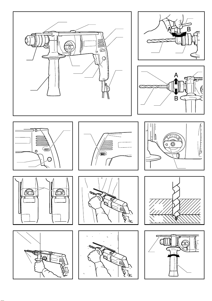
MOUNTING AND REMOVING THE BIT (Fig. 1, 2)
(PD-2070VR) (Fig. 1)
1. Insert the bit (3) into the chuck (1) as far as it will go.
2. Then, tighten the chuck securely with the chuck key (2) provided.
(There are three holes in the chuck. Insert the chuck key into each
hole in turn and tighten by turning evenly in direction A.)
3. The bit can be removed by inserting the chuck key into any of the
three holes and turning in direction B.
(PD-2080VR) (Fig. 2)
(Mounting)
1. To open the drill chuck (15), hold the ring (16) securely and turn the
sleeve (17) in direction A.
2. Insert the bit (3) into the chuck as far as it will go.
3. Hold the ring securely and turn the sleeve in direction B until the chuck
is tightened and you hear a click.
4. After the click, further tighten the chuck.
(Removing)
1. Hold the ring securely and turn the sleeve in direction A.
2. After loosening the chuck, remove the bit.
SWITCH (Fig. 3)
This tool is started and stopped by squeezing and releasing the trigger (4).
The speed can be adjusted from 0 through 2,700 min.
and from 0 through 1,250 min.
squeezing force.
For continuous operation, press the lock button (5) while squeezing the
trigger. Squeeze again to release the lock.
CHANGING THE ROTATION DIRECTION (Figs. 3, 4)
To change the rotation direction, stop the tool and push the forward button
(12) or reverse button (11).
When the forward button is pushed in, the bit rotates clockwise when viewed
from the handle end of the tool.
When the reverse button is pushed in, the bit rotates counterclockwise.
CHANGING THE ROTATION SPEED (Fig. 5)
The rotation speed can only be changed when the tool is at a standstill.
The gear setting knob (6) is on the left side of the housing.
When the knob is in position “1”, the tool is in the low gear.
When the knob is in position “2”, the tool is in the high gear.
-1
in the low gear, by controlling the trigger-
-1
(HE08)
in the high gear,
CHANGING BETWEEN DRILLING AND IMPACT
DRILLING MODE (Fig. 6)
The drilling mode shift knob (7) for changing between the drilling mode and
impact drilling mode is positioned on the top of the tool.
DRILLING MODE : Shift the knob to the “ ” symbol for rotation without
impact action.
IMPACT DRILLING MODE : Shift the knob to the “ ” symbol for impact
drilling.
OPERATING
NEVER COVER THE AIR VENTS (10) SINCE THEY MUST ALWAYS BE
OPEN FOR PROPER MOTOR COOLING.
DRILLING IN WOOD (Figs. 7, 8)
To prevent ugly splits around the drill hole on the reverse side of the work
piece (13), put a piece of scrap lumber (14) under the work piece.
DRILLING IN METAL (Fig. 9)
Metals such as steel brass, aluminum sheets, stainless steel, and pipe
may also be drilled. Mark the point to be drilled with a nail or punch.

DRILLING IN CONCRETE (Fig. 10)
Rock and masonry are generally drilled in the impact drilling mode.
When drilling in delicate materials such as wall tiles, it is essential to start
with ordinary drilling and, once the tile is pierced, to continue with impact
drilling.
In deep bore holes the drill bit should be pulled out occasionally in order to
remove the dust and chips from the hole.
AUXILIARY HANDLE AND STOPPER POLE (Fig. 11)
AUXILIARY HANDLE
The auxiliary handle (9) can be rotated 360°.
Loosen the handle grip by turning in direction A, and tighten it at an easyto-use position by turning the grip in direction B.
STOPPER POLE
By using the stopper pole (8), holes of a fixed depth can be accurately
bored.
The depth of the hole will be the distance from the end of the bit to the end
of the stopper pole.
By turning the handle grip in direction A, the stopper pole can be released
and the depth adjusted. After adjusting the depth, fix the stopper pole again
by turning the handle grip in direction B.
MAINTENANCE
After use, check the tool to make sure that it is in top condition.
It is recommended that you take this tool to a RYOBI Authorized Service
Center for a thorough cleaning and lubrication at least once a year.
DO NOT MAKE ANY ADJUSTMENTS WHILE THE MOTOR IS IN
MOTION.
ALWAYS DISCONNECT THE POWER CORD FROM THE RECEPT ACLE
BEFORE CHANGING REMOVABLE OR EXPENDABLE P ARTS (BLADE,
BIT, SANDING PAPER ETC.), LUBRICATING OR WORKING ON THE
UNIT.
WARNING!
To ensure safety and reliability, all repairs should be performed by an
AUTHORIZED SERVICE CENTER or other QUALIFIED SERVICE
ORGANIZATION.
SAVE THESE INSTRUCTIONS FOR FUTURE REFERENCE.
(HE08)

WIR DANKEN IHNEN FÜR DAS VERTRAUEN, DAS
SIE DURCH DEN KAUF DIESES RYOBI-GERÄTES
GEZEIGT HABEN.
Zu Ihrer Sicherheit und um optimale Leistungen zu gewährleisten,
lesen Sie diese BEDIENUNGSANLEITUNG und die
SICHERHEITSVORSCHRIFTEN vor der Benutzung des Geräts durch.
BESCHREIBUNG
1. Bohrfutter
2. Bohfutterschlüssel
3. Bohreinsatz
4. Ein-/Ausschalter
5. Arretierknopf
6. Drehzahlsteuerung
7. Umschalter zur Einstellung der Betriebsart
8. Tiefenanschlag
9. Zusatzhandgriff
10. Lüftungschlitze
11. Linkslaufknopf
12. Rechtslaufknopf
13. Werkstück
14. Unterlegholzblock
15. Bohrfutter
16. Ring
17. Hülse
BETRIEBSANWEISUNGEN
1. Vergewissern Sie sich, daß das Gerät nur an ein Netz mit der auf
dem Typenschild angegebenen Spannung angeschlossen ist.
2. Benutzen Sie das Gerät auf keinen Fall, wenn die Schutzhaube oder
Schrauben fehlen. Wurden die Schutzhaube oder Schrauben entfernt,
bringen Sie diese vor dem Einsatz des Geräts erneut an. Stellen Sie
stets den einwandfreien Zustand der Geräteteile sicher.
3. Befestigen Sie Werkzeuge immer, wenn Sie in erhöhter Stellung
arbeiten.
4. Berühren Sie niemals Klingen, Werkzeugeinsätze, Schleifscheiben
oder andere rotierende Teile während des Betriebs.
5. Schalten Sie das Gerät niemals ein, wenn die rotierende
Gerätekomponente das Werkstück berührt.
6. Stellen Sie das Gerät niemals ab, solange bewegliche Teile nicht
vollkommen zum Stillstand gekommen sind.
7. ZUBEHÖR : Die Benutzung von Zubehör und Einrichtungen, die nicht
in dieser Anleitung beschrieben sind, ist gefährlich.
8. ERSATZTEILE : Benutzen Sie zur Wartung nur Original-Ersatzteile
von Ryobi.
SICHERHEITSVORSCHRIFTEN FÜR DEN
SCHLAGBOHRER
1. Vergewissern Sie sich, daß der Bohreinsatz richtig montiert ist. Ein
falsch montierter Bohreinsatz ist äußerst gefährlich, da er während
des Betriebs aus dem Bohrfutter geschleudert werden oder abbrechen
kann.
2. Tragen Sie weder Handschuhe noch Krawatte. Sie könnten von dem
rotierenden Bohreinsatz mitgezogen werden.
3. Halten Sie das Werkzeug immer mit beiden Händen fest, um Unfällen
und Verletzungen vorzubeugen.
4. Berühren Sie beim Bohren in Wänden, Fußböden oder anderen
Oberflächen, in denen elektrische Kabel verlaufen, niemals das
Bohrfutter oder die Metallteile. Halten Sie das Gerät immer am
Kunststoffgriff fest, um eine Stromschlaggefahr auszuschalten.
5. Das Werkstück muß beim Bohren mit Hilfe einer Klemmzange oder
einer Zwinge befestigt werden, damit es nicht verschoben wird
(Bohrfutterdrehung).
SPEZIFIKATIONEN
Bohrfutterspannbereich 13 mm 13 mm
Bohrdurchmesser in
Holz 40 mm 40 mm
Metall 13 mm 13 mm
Beton 20 mm 20 mm
Frequenz 50 Hz 50 Hz
Netzspannung * 110 V, 230 V 110 V, 230V
Leistung 710 W 710W
Leerlaufdrehzahl
max. 0 - 2.700 min.
min. 0 - 1.250 min.-10 - 1.250 min.
Schlagzahl pro Minute
max. 0 - 43.200 min.
min. 0 - 20.000 min.-10 - 20.000 min.
Gesamtlänge 365 mm 371 mm
Nettogewicht 2,4 kg 2,6 kg
* Sehen Sie auf jeden Fall auf dem Typenschild nach, denn die
Netzspannung kann je nach Land unterschiedlich sein.
STANDARDZUBEHÖR
Zusatzhandgriff, Tiefenanschlag, Bohrfutterschlüssel (nur mit dem Modell
PD-2070VR)
ANWENDUNGSBEREICH
(Verwenden Sie das Gerät nur für die unten aufgeführten Anwendungen.)
1. Bohren in Holz, Metall und Kunststoff.
2. Bohren in Beton (nur Schlagbohrer).
SCHALLEISTUNGSPEGEL
Die Schalleistungspegel (Schalldruckpegel) kann am Arbeitsplatz 85 dB
(A) überschreiten. In diesem Fall sind Schallschutz- und
Gehörschutzmaßnahmen für den Bedienenden erforderlich.
PD-2070VR PD-2080VR
-1
0 - 2.700 min.
-1
0 - 43.200 min.
(HE08)
-1
-1
-1
-1
EINSETZEN UND ENTFERNEN DES
BOHREINSATZES (Abb. 1, 2)
DEN NETZSTECKER DES GERÄTS ZIEHEN, BEVOR SIE DEN
BOHREINSATZ EINSETZEN BZW. HERAUSNEHMEN.
(PD-2070VR) (Abb. 1)
1. Führen Sie den Bohreinsatz (3) so weit wie möglich in das Bohrfutter
(1) ein.
2. Spannen Sie nun das Bohrfutter mit Hilfe des mitgelieferten
Bohrfutterschlüssels (2).
(Das Bohrfutter ist mit drei Bohrungen versehen. Setzen Sie
nacheinander den Schlüssel in jede Bohrung ein und spannen Sie
das Futter fest, indem Sie den Schlüssel in Richtung A drehen.)
3. Setzen Sie den Bohrfutterschlüssel in jede der drei Bohrungen ein
und drehen Sie den Schlüssel in Richtung B, um den Bohreinsatz zu
entfernen.
(PD-2080VR) (Abb. 2)
(Einsetzen)
1. Zum Öffnen des Bohrfutters (15) den Ring (16) festhalten und die
Hülse (17) in Richtung A drehen.
2. Führen Sie den Bohreinsatz (3) ganz in das Bohrfutter ein.
3. Halten Sie den Ring fest und drehen Sie die Hülse in Richtung B, bis
sie mit einem hörbaren Geräusch einrastet.
4. Spannen Sie dann das Bohrfutter weiter.
(Herausnehmen)
1. Halten Sie den Ring fest und drehen Sie die Hülse in Richtung A.
2. Nachdem Sie das Bohrfutter gelöst haben, nehmen Sie den
Bohreinsatz heraus.
EIN-/AUSSCHALTER (Abb. 3)
Das Werkzeug wird durch Betätigung des Ein-/Ausschalters (4) in Betrieb
bzw. außer Betrieb gesetzt.
Die Drehzahl kann je nach Druck auf den Ein-/Ausschalter von 0 bis
-1
2.700 min.
Sanftlauf-Betrieb eingestellt werden.
Dauerschaltung: Betätigen Sie den Arretierknopf (5) und drücken Sie
weiterhin den Ein-/Ausschalter. Betätigen Sie den Arretierknopf erneut, um
ihn freizugeben.
für den Schnellauf-Betrieb und von 0 bis 1.250 min.-1 für den

ÄNDERUNG DER DREHRICHTUNG (Abb. 3, 4)
Wenn Sie die Drehrichtung ändern möchten, stoppen Sie das Gerät und
drücken Sie den Rechtslaufknopf (12) oder den Linkslaufknopf (11).
Ist der Rechtslaufknopf gedrückt, dreht sich der Bohreinsatz im
Uhrzeigersinn (vom hinteren Ende des Griffs aus gesehen).
Ist der Linkslaufknopf gedrückt, dreht sich der Bohreinsatz im
Gegenuhrzeigersinn.
ÄNDERUNG DER DREHZAHL (Abb. 5)
Die Drehzahl läßt sich nur ändern, wenn das Gerät stillsteht.
Der Drehzahlschalter (6) befindet sich links am Schutzgehäuse.
Befindet sich der Schalter auf Position “1”, läuft das Gerät mit der minimalen
Drehzahl.
Befindet sich der Schalter auf Position “2”, läuft das Gerät mit der maximalen
Drehzahl.
UMSCHALTEN BOHREN / SCHLAGBOHREN (Abb. 6)
Der zum Einstellen der Betriebsart vorgesehene Umschalter (7) befindet
sich auf der Oberseite des Geräts. Durch Betätigung des Umschalters kann
von der Betriebsart Bohren in die Betriebsart Schlagbohren und umgekehrt
umgeschalten werden.
BOHREN: Schieben Sie den Umschalter auf das Symbol “ ”, um
normal zu bohren.
SCHLAGBOHREN: Schieben Sie den Umschalter auf das Symbol “ ”,
um schlagzubohren.
INBETRIEBNAHME
WARNHINWEIS!
DECKEN SIE NIEMALS DIE LÜFTUNGSSCHLITZE (10) AB, DENN SIE
SORGEN FÜR DIE KORREKTE ABKÜHLUNG DES MOTORS.
BOHREN IN HOLZ (Abb. 7, 8)
Um ein Zersplittern beim Durchbrechen zu vermeiden, legen Sie das
Unterlegholz unter den Bohrbereich.
BOHREN IN METALL (Abb. 9)
Sie können gleichermassen Metall wie z.B. Stahl-, Kupfer-, Aluminium- und
rostfreie Stahlfolien und Rohre bohren. Markieren Sie die Bohrstelle mit
Hilfe eines Nagels oder Stiftes.
BOHREN IN BETON (Abb. 10)
Bei Stein und Beton wird üblicherweise die Schlagbohrtechnik angewandt.
Bei brüchigen Werkstoffen wie Fliesen ist es ratsam, zuerst normal ohne
Schlagbohren vorzubohren. Dann kann mit Schlagbohren fortgesetzt werden.
Bei tiefen Bohrlöchern ist es ratsam, den Bohrer in regelmäßigen Abständen
aus der Bohrung herauszuziehen, um Staub und Rückstände zu beseitigen.
ZUSATZHANDGRIFF UND TIEFENANSCHLAG
(Abb. 11)
ZUSATZHANDGRIFF
Der Zusatzhandgriff (9) kann um 360° gedreht werden.
Lösen Sie den Griff, indem Sie ihn in Richtung A drehen, und spannen Sie
den Griff in der gewünschten Position, indem Sie ihn in Richtung B drehen.
TIEFENANSCHLAG
Durch Anbringen des Tiefenanschlags (8) lassen sich Löcher mit fester
Tiefe bohren.
Die Tiefe der Bohrung entspricht dem Abstand zwischen der Spitze des
Bohreinsatzes und jener des Tiefenanschlags.
Wird der Griff in Richtung A gedreht, wird der Tiefenanschlag freigegeben,
und die Tiefe kann eingestellt werden. Sobald sie eingestellt ist, drehen Sie
den Griff in Richtung B, um den Tiefenanschlag zu arretieren.
WARTUNG
Prüfen Sie das Gerät nach jedem Einsatz auf seinen einwandfreien
Betriebszustand.
Wir empfehlen, das Gerät mindestens einmal jährlich zwecks gründlicher
Reinigung und Schmierung zu einem autorisierten RYOBI-Servicecenter
zu bringen.
NEHMEN SIE KEINE EINSTELLUNGEN VOR, SOLANGE DER MOTOR
LÄUFT.
TRENNEN SIE VOR DEM AUSBAU ODER ERSATZ VON
ABNEHMBAREN TEILEN ODER VON VERSCHLEISSTEILEN
(KLINGEN, WERKZEUGEINSÄTZE, SCHLEIFPAPIER USW.) SOWIE
VOR DER SCHMIERUNG UND DER REPARA TUR DES GERÄTS IMMER
DEN STECKER VOM GEHÄUSE.
(HE08)

LE AGRADECEMOS QUE HAYA COMPRADO UN
PRODUCTO RYOBI.
Para garantizar su seguridad y obtener plena satisfacción de esta
máquina, antes de utilizarla lea atentamente el presente MANUAL DE
INSTRUCCIONES y siga las REGLAS DE SEGURIDAD recomendadas.
DESCRIPCIÓN
1. Mandril
2. Llave del mandril
3. Broca
4. Interruptor
5. Botón de bloqueo
6. Botón de regulación de velocidad
7. Botón de cambio de modo de taladrado
8. Tope de profundidad
9. Asa auxiliar
10. Ranuras de aireación
11. Botón de rotación hacia la izquierda
12. Botón de rotación hacia la derecha
13. Pieza de trabajo
14. Cuña de madera
15. Mandril
16. Anillo
17. Manguito
REGLAS DE TRABAJO
1. Verifique que la herramienta esté enchufada en una alimentación cuyo
voltaje corresponde al voltaje indicado en la placa de identificación.
2. No utilice la herramienta en ningún caso si faltara la tapa de protección
o alguna de las tuercas. Si se ha retirado la tapa de protección o las
tuercas, colóquelas nuevamente en su lugar antes de utilizar la
máquina. Controle que todos los elementos estén en perfectas
condiciones de utilización.
3. Sujete siempre firmemente su máquina si debe trabajar en un sitio
elevado.
4. No toque, en ningún caso, la cuchilla, la fresa, la muela o cualquier
otro elemento en rotación.
5. En ningún caso ponga en marcha la herramienta cuando el elemento
de corte (el que trabaja en rotación) está en contacto con la pieza
que va a trabajar.
6. No suelte la máquina hasta que todas sus piezas móviles se hayan
detenido completamente.
7. ACCESORIOS : La utilización de accesorios o de equipos que no
figuren en las recomendaciones de este manual puede resultar
peligrosa.
8. PIEZAS DE REPUESTO : En caso de necesitar una reparación, utilice
exclusivamente piezas de repuesto idénticas a las de la máquina.
CONSIGNAS DE SEGURIDAD RELATIVAS A LA
TALADRADORA A PERCUSIÓN
1. Asegúrese de que la broca está correctamente instalada. Una broca
mal instalada es sumamente peligrosa, ya que puede soltarse o
romperse durante el taladrado.
2. No utilice ni guantes ni corbata, porque podrían quedar atrapados en
la broca en rotación.
3. Sujete la máquina firmemente con ambas manos para evitar riesgos
de accidentes o heridas.
4. No toque nunca el mandril ni las partes metálicas cuando esté
perforando paredes, suelos u otras superficies debajo de las cuales
haya cables de electricidad. Sujete la máquina únicamente por el
asa de plástico para evitar todo riesgo de electrocución.
5. Mientras esté utilizando la máquina, la pieza de trabajo debe estar
fijada firmemente con una brida de fijación u otro instrumento
adecuado, para evitar que se mueva como consecuencia de la
rotación del mandril.
ESPECIFICACIONES
Capacidad del mandril 13 mm 13 mm
Capacidad de taladrado
madera 40 mm 40 mm
metal 13 mm 13 mm
cemento 20 mm 20 mm
Frecuencia 50 Hz 50 Hz
Tensión* 110 V, 230 V 110 V, 230V
Potencia 710 W 710 W
Velocidad sin carga
máx. 0 - 2.700 min.
mín. 0 - 1.250 min.-10 - 1.250 min.
Golpes por minuto
máx. 0 - 43.200 min.
mín. 0 - 20.000 min.-10 - 20.000 min.
Largo total 365 mm 371 mm
Peso neto 2,4 kg 2,6 kg
* Procure verificar la placa de características del producto, ya que
ésta puede variar en función del país.
ACCESORIOS STANDARD
Asa auxiliar, tope de profundidad, llave del mandril (sólo Pd-2070VR)
APLICACIONES
Esta máquina se debe utilizar exclusivamente para las siguientes tareas:
1. Taladrado de superficies de madera, metal y plástico.
2. Taladrado de cemento (únicamente taladrado a percusión).
NIVEL DE RUIDO AMBIENTAL
El ruido (nivel de intensidad sonora) en el taller puede superar los 85 dB
(A). En este caso, el operario debe adoptar medidas de aislamiento sonoro
o de protección contra el ruido.
MONTAJE Y DESMONTAJE DE LA BROCA (Fig. 1, 2)
ANTES DE MONTAR Y DESMONT AR LA BROCA ASEGÚRESE DE QUE
EL APARATO ESTÉ DESCONECTADO DE LA RED ELÉCTRICA.
(PD-2070VR) (Fig. 1)
1. Inserte la broca (3) en el mandril (1) tan profundamente como sea
posible.
2. Luego ajuste el mandril utilizando la llave del mandril (2) provista.
(Hay tres orificios en el mandril. Inserte la llave del mandril en cada
uno de los tres orificios sucesivamente y ajústelos sin vacilaciones en
la dirección A).
3. Para retirar la broca, inserte la llave del mandril en cada uno de los
tres orificios y gire en la dirección B.
(PD-2080VR) (Fig. 2)
(Montaje)
1. Para aflojar el mandril (15), sujete con firmeza el anillo (16) y gire el
manguito (17) en la direcci—n A.
2. Inserte la broca (3) hasta el fondo del mandril.
3. Sujete con firmeza el anillo y gire el manguito en la direcci—n B hasta
que oiga un clic.
4. A continuaci—n, apriete el mandril.
(Desmontaje)
1. Sujete con firmeza el anillo y gire el manguito en la direcci—n A.
2. Cuando el mandril esté flojo, retire la broca.
INTERRUPTOR (Fig. 3)
Esta herramienta se pone en marcha y se detiene haciendo presión en un
interruptor (4).
La velocidad puede regularse de 0 a 2.700 min.
-1
1.250 min.
Si hace un uso continuo de la máquina, pulse el botón de bloqueo (5) al
mismo tiempo que aprieta el interruptor. Pulse nuevamente para desbloquear
el botón.
en modo lento, según la presión ejercida en el interruptor.
PD-2070VR PD2080VR
-1
0 - 2.700 min.
-1
0 - 43.200 min.
-1
en modo rápido, y de 0 a
(HE08)
-1
-1
-1
-1
 Loading...