


OPERATOR’S MANUAL
MANUEL D’UTILISATION
MANUAL DEL OPERADOR
18 VOLT STRING TRIMMER/EDGER
18 V TONDEUSE À FOUET/TAILLE-BORDURE
18 V RECORTADORA DE HILO/
RECORTADORA DE BORDES
P2005
ACCEPTS ALL ONE+ BATTERY PACKS
BATTERIES AND CHARGERS SOLD SEPARATELY
COMPATIBLE AVEC TOUS LE BATTERIES ONE+
BATTERIES ET CHARGEUR VENDUS SÉPARÉMENT
ACEPTA TODOS LOS PAQUETES DE BATERÍAS ONE+
LAS BATERÍAS Y EL CARGADOR SE VENDEN POR SEPARADO
Your trimmer has been engineered and manufactured to our high standard for dependability, ease of operation, and operator safety. When properly cared for, it will give you years of rugged, trouble-free performance.
 WARNING: To reduce the risk of injury, the user must read and understand the operator’s manual before using this product.
Thank you for your purchase.
SAVE THIS MANUAL FOR FUTURE REFERENCE
Le taille-bordures à ligne a été conçue et fabriquée conformément à nos strictes normes de fiabilité, simplicité d’emploi et sécurité d’utilisation.Correctemententretenue,ellevousdonneradesannées de fonctionnement robuste et sans problème.
 AVERTISSEMENT : Pour réduire les risques de blessures, l’utilisateur doit lire et veiller à bien comprendre le manuel d’utilisation avant d’employer ce produit.
Merci de votre achat.
Su recortadoras de hilo ha sido diseñada y fabricada de conformidad con las estrictas normas para brindar fiabilidad, facilidad de uso y seguridad para el operador. Con el debido cuidado, le brindará muchos años de sólido y eficiente funcionamiento.
 ADVERTENCIA: Para reducir el riesgo de lesiones, el usuario debe leer y comprender el manual del operador antes de usar este producto.
Le agradecemos su compra.
CONSERVER CE MANUEL POUR |
GUARDE ESTE MANUAL PARA |
FUTURE RÉFÉRENCE |
FUTURAS CONSULTAS |
See this fold-out section for all the figures referenced in the operator’s manual.
Voir que cette section d’encart pour toutes les figures a adressé dans le manuel d’utilisation.
Vea esta sección de la página desplegable para todas las figuras mencionó en el manual del operador.
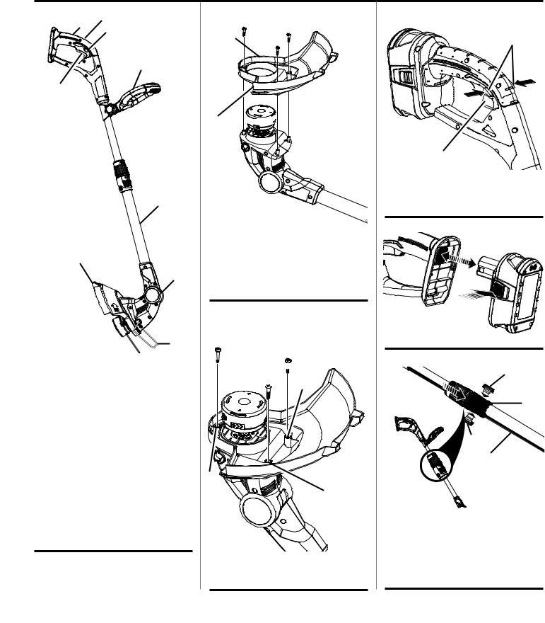
Fig. 1 |
E |
|
B |
|
C |
D
A
F
I
G
H
A - Switch trigger (gâchette, gatillo del interruptor)
B - GripZone™ overmold (surmoulage GripZone™, sobremoldeado GripZone™)
C - Lock-out button (bouton de verrouillage, botón de seguro de seguro)
D - Adjustable front handle (poignée avant réglable, mango delantero ajustable)
E - Rotating rear handle (poignée arrière rotative, mango delantero ajustable)
F - Telescoping boom (flèche télescopique, brazo telescópico)
G - 3-Position pivoting head (tête pivotante à trois positions, cabezal pivotante)
H - Edger guide (guidage du taille-bordure, guía para recortar bordes)
I- Grass defector (déflecteur d’herbe, deflector de hierba)
Fig. 2
A
C 
 B
B
A - Grass deflector (déflecteur d’herbe, deflector de hierba)
B - Slide over head and turn counterclockwise (faire glisser sur la tête et tourner dans le sens anti-horaire, deslizarlo sobre el cabezal y girarlo en sentido antihorario)
C - Line cut-off blade (lame de sectionnement de ligne, cuchilla de corte del hilo)
Fig. 3
 B
B
 B
B
B 
 A
A
A
A
A - Screw holes (orifices de las vis, agujeros del tornillo)
B - Screws (vis, tornillos)
Fig. 4
A
B
A - Lock-out button (bouton de verrouillage, botón de seguro de seguro)
B - Switch trigger (gâchette, gatillo del interruptor)
Fig. 5
A 
A - Latches (loquets, pestillos)
Fig. 6
B
D
C
A
A - Telescoping boom (flèche télescopique, brazo telescópico)
B - Loosen (desserrer, aflojar) C - Tighten (aflojar, asegurar)
D - Telescoping boom coupler (coupleur du flèche télescopique, acoplador del brazo telescópico)
ii

Fig. 7
A
A - Knob (bouton, perilla)
Fig. 8
B
A
C
A - Pivot button (bouton de pivot, botón del pivote)
B - Notches 1 and 2: trimming and edging (enchoches 1 et 2 : taille et coupe, muescas 1 y 2: rocartar y cortar bordes)
C - Notch 3: storage position only (enchoche 3 : position de rangement seulement, muesca 3: posición solamente)
Fig. 9
PROPER TRIMMER
OPERATING POSITION
POSITION D’UTILISATION CORRECTE
POUR TAILLE-HAIES
POSICIÓN CORRECTA PARA EL MANEJO
DE LA CORTADORA
Fig. 10
A
C
B
A - Direction of rotation (sens de rotation, sentido de la rotación)
B - Best cutting area (d’efficacité, área de corte óptima)
C - Dangerous cutting area (zone de coup dangereuse, área de corte peligrosa)
Fig. 11
B 


 A
A
A - Black button (bouton noir, botón negro) B - String (fils, hilo)
Fig. 12
A
B
A - Edger guide (guidage de bordure, guía para el recorte de bordes)
B - Line cut-off blade (lame coupe-ligne, cuchilla de corte)
Fig. 13 A
B
A - Rotating rear handle (poignée arrière rotative, mango delantero ajustable)
B - Edging coupler (coupleur du taille-bordure, acoplador para cortar bordes)
Fig. 14
PROPER EDGING OPERATING POSITION
POSITION D’UTILISATION CORRECTE
POUR COUPE-BORDURES
POSICIÓN CORRECTA PARA EL MANEJO
DE LA CORTAR BORDES
Fig. 15
A 


 C
C
B
D 

E
A - Spool retainer (retenue de bobine, retén del carrete)
B - Spool (bobine, carrete)
C - Tabs (languettes, pestañas) D - Slots (fentes, ranuras)
E - Eyelet (trou, agujero)
Fig. 16 |
WIND CLOCKWISE |
|
|
ENROULER DANS LE SENS HORAIRE |
|
ENROLLE HACIA LA DERECHA |
|
|
A |
|
B |
A - Spool (bobine, carrete)
B - Hole (trou, agujero)
iii

TABLE OF CONTENTS
TABLE DES MATIÈRES / ÍNDICE DE CONTENIDO
Introduction....................................................................................................................................................................... |
2 |
Introduction / Introducción |
|
Important Safety Instructions......................................................................................................................................... |
3-4 |
Instructions importantes concernant la securite / Instrucciones de seguidad importantes |
|
Symbols............................................................................................................................................................................ |
5 |
Symboles / Símbolos |
|
Features............................................................................................................................................................................ |
6 |
Caractéristiques / Características |
|
Assembly........................................................................................................................................................................ |
6-7 |
Assemblage / Armado |
|
Operation....................................................................................................................................................................... |
7-8 |
Utilisation / Funcionamiento |
|
Maintenance...................................................................................................................................................................... |
9 |
Entretien / Mantenimiento |
|
Troubleshooting............................................................................................................................................................... |
10 |
Dépannage / Corrección de problemas |
|
Warranty.......................................................................................................................................................................... |
11 |
Garantie / Garantía |
|
Parts Ordering and Service................................................................................................................................ |
Back Page |
Commande de pièces et réparation / Pedidos de piezas y servicio.......................................................... |
Page arrière / Pág. posterior |
INTRODUCTION
INTRODUCTION / INTRODUCCIÓN
This product has many features for making its use more pleasant and enjoyable. Safety, performance, and dependability have been given top priority in the design of this product making it easy to maintain and operate.
* * *
Ce produit offre de nombreuses fonctions destinées à rendre son utilisation plus plaisante et satisfaisante. Lors de la conception de ce produit, l’accent a été mis sur la sécurité, les performances et la fiabilité, afin d’en faire un outil facile à utiliser et à entretenir.
* * *
Este producto ofrece numerosas características para hacer más agradable y placentero su uso. En el diseño de este producto se ha conferido prioridad a la seguridad, el desempeño y la fiabilidad, por lo cual se facilita su manejo y mantenimiento.
2 — English

IMPORTANT SAFETY INSTRUCTIONS
WARNING!
When using electric gardening appliances, basic safety precautions should always be followed to reduce the risk of fire, electric shock and personal injury.
READ ALL INSTRUCTIONS
For safe operation, read and understand all instructions before using this product. Follow all safety instructions. Failure to follow all safety instructions listed below, can result in serious personal injury.
Do not allow children or untrained individuals to use this unit.
Check the work area before each use. Remove all objects such as rocks, broken glass, nails, wire, or string which can be thrown or become entangled in the machine.
Always wear eye protection with side shields marked to comply with ANSI Z87.1. Following this rule will reduce the risk of serious personal injury.
Use Safety Glasses – Always wear safety glasses with side shields. Everyday glasses have only impact resistant lenses. They are NOT safety glasses. Following this rule will reduce the risk of eye injury.
Protect your lungs. Wear a face or dust mask if the operation is dusty. Following this rule will reduce the risk of serious personal injury.
Dress Properly – Use of rubber gloves and substantial footwear is recommended when working outdoors. Wear heavy, long pants, long sleeves, boots, and gloves. Do not wear loose fitting clothing, short pants, sandals, or go barefoot. Do not wear jewelry of any kind.
Secure long hair above shoulder level to prevent entanglement in moving parts.
Keep children away - Keep all bystanders, children, and pets at least 50 ft. away.
Stay alert - Do not operate this unit when you are tired, ill, or under the influence of alcohol, drugs, or medication.
Do not operate in poor lighting.
Keep all parts of your body away from any moving part.
Do not operate power tools in explosive atmospheres, such as in the presence of flammable liquids, gases, or dust. Power tools create sparks which may ignite the dust or fumes.
Avoid body contact with grounded surfaces such as pipes, radiators, ranges, and refrigerators. There is an increased risk of electric shock if your body is grounded.
Avoid Dangerous Environments - Don’t expose appliance
or string trimmer to rain or wet conditions. Water entering an appliance or string trimmer will increase the risk of electric shock.
Use Right Appliance - Do not force tool. Use the correct tool for your application. The correct tool will do the job better and safer at the rate for which it is designed.
Don’t Force Appliance – It will do the job better and with less likelihood of a risk of injury at the rate for which it was designed.
Do not operate the equipment while barefoot or when wearing sandals or similar lightweight footwear. Wear protective footwear that will protect your feet and improve your footing on slippery surfaces.
Do not overreach. Keep firm footing and balance. Overreaching can result in loss of balance.
Avoid accidental starting. Be sure switch trigger is in the locked or off position before inserting battery pack. Carrying tools with your finger on the switch trigger or inserting the battery pack into a tool with the switch on invites accidents.
Do not use tool if switch trigger does not turn it on or off. Any tool that cannot be controlled with the switch trigger is dangerous and must be repaired.
Disconnect battery pack from the appliance before storing, servicing, or changing accessories such as cutting line. Such preventive safety measures reduce the risk of starting the tool accidentally.
Use only identical manufacturer’s replacement parts and accessories. Use of any other parts may create a hazard or cause product damage.
Maintain appliance with care - Replace string head if cracked, chipped, or damaged in any way. Be sure the string head is properly installed and securely fastened. Failure to do so can cause serious injury. Keep handles dry, clean and free from oil and grease.
Check for damaged parts. Before further use of the tool, any part that is damaged should be carefully checked to determine that it will operate properly and perform its intended function. Check for alignment of moving parts, binding of moving parts, breakage of parts, mounting, and any other conditions that may affect its operation. A guard or other part that is damaged should be properly repaired or replaced by an authorized service dealer.
3 — English

IMPORTANT SAFETY INSTRUCTIONS
Make sure all guards, straps, deflectors and handles are properly and securely attached.
Use only the manufacturer’s replacement string in the cutting head. Do not use any other cutting attachment, for example, metal wire, rope, or the like. To install any other brand of cutting head to this string trimmer can result in serious personal injury.
Never operate unit without the grass deflector in place and in good condition.
Maintain a firm grip on both handles while trimming. Keep string head below waist level. Never cut with the string head located over 30 in. or more above the ground.
Store idle appliances indoors - When not in use, string trimmer should be stored indoors in a dry, locked place out of the reach of children.
Never use blades, flailing devices, wire or rope. Unit is designed for line trimmer use only. Use of any other accessories or attachments will increase the risk of injury.
Inspect area to be cut. Remove objects (rocks, broken glass, nails, wire, string, etc.) which can be thrown or become entangled in cutting head.
Keep the air vents clean and free of debris to avoid overheating the motor. Clean after each use.
Stop the unit and disconnect the power source when not in use. Carry the unit with the motor stopped.
Store out of the reach of children.
Do not hang unit so that the switch trigger is depressed.
Battery tools do not have to be plugged into an electrical outlet; therefore, they are always in operating condition. Be aware of possible hazards when not using your battery tool or when changing accessories. Following this rule will reduce the risk of electric shock, fire, or serious personal injury.
Do not charge battery tool in rain, or damp or wet location. Following this rule will reduce the risk of electric shock.
Do not use battery-operated appliance in rain.
Remove or disconnect battery before servicing, cleaning or removing material from the gardening appliance.
Use battery only with charger listed. For use with 18V nickel-cadmium and lithium-ion battery packs. See Tool/ Appliance/Battery Pack/Charger Correlation Supplement 987000-432.
Do not dispose of the batteries in a fire. The cell may explode. Check with local codes for possible special disposal instructions.
Do not open or mutilate the batteries. Released electrolyte is corrosive and may cause damage to the eyes or skin. It may be toxic if swallowed.
Do not place battery tools or their batteries near fire or heat. This will reduce the risk of explosion and possibly injury.
Batteries can explode in the presence of a source of ignition, such as a pilot light. To reduce the risk of serious personal injury, never use any cordless product in the presence of open flame. An exploded battery can propel debris and chemicals. If exposed, flush with water immediately.
Do not crush, drop or damage battery pack. Do not use a battery pack or charger that has been dropped or received a sharp blow. A damaged battery is subject to explosion. Properly dispose of a dropped or damaged battery immediately.
Exercise care in handling batteries in order not to short the battery with conducting materials such as rings, bracelets, and keys. The battery or conductor may overheat and cause burns.
For best results, your battery tool should be charged in a location where the temperature is more than 50°F but less than 100°F. To reduce the risk of serious personal injury, do not store outside or in vehicles.
Under extreme usage or temperature conditions, battery leakage may occur. If liquid comes in contact with your skin, wash immediately with soap and water, then neutralize with lemon juice or vinegar. If liquid gets into your eyes, flush them with clean water for at least 10 minutes, then seek immediate medical attention. Following this rule will reduce the risk of serious personal injury.
Save these instructions. Refer to them frequently and use them to instruct others who may use this power tool. If you loan someone this power tool, loan them these instructions also.
4 — English

SYMBOLS
The following signal words and meanings are intended to explain the levels of risk associated with this product.
SYMBOL |
SIGNAL |
MEANING |
|
|
|
|
DANGER: |
Indicates an imminently hazardous situation, which, if not avoided, will result |
|
in death or serious injury. |
|
|
|
|
|
|
|
|
WARNING: |
Indicates a potentially hazardous situation, which, if not avoided, could result |
|
in death or serious injury. |
|
|
|
|
|
|
|
|
CAUTION: |
Indicates a potentially hazardous situation, which, if not avoided, may result in |
|
minor or moderate injury. |
|
|
|
|
|
|
|
|
CAUTION: |
(Without Safety Alert Symbol) Indicates a situation that may result in property |
|
damage. |
|
|
|
Some of the following symbols may be used on this product. Please study them and learn their meaning. Proper interpretation of these symbols will allow you to operate the product better and safer.
SYMBOL |
NAME |
DESIGNATION/EXPLANATION |
|
|
Safety Alert |
Indicates a potential personal injury hazard. |
|
|
Read Operator’s |
To reduce the risk of injury, user must read and understand operator’s |
|
|
Manual |
manual before using this product. |
|
|
Eye Protection |
Always wear eye protection with side shields marked to comply |
|
|
with ANSI Z87.1. |
|
|
|
|
|
|
|
Wet Conditions Alert |
Do not expose to rain or use in damp locations. |
|
|
Keep Bystanders |
Keep all bystanders at least 50 ft. away. |
|
|
Away |
||
|
|
|
|
|
Ricochet |
Thrown objects can ricochet and result in personal injury or property |
|
|
damage. |
|
|
|
|
|
|
|
No Blade |
Do not install or use any type of blade on a product displaying this |
|
|
symbol. |
|
|
|
|
|
|
|
|
This product uses nickel-cadmium (Ni-Cd) and lithium-ion (Li-ion) |
|
|
Recycle Symbols |
batteries. Local, state, or federal laws may prohibit disposal of |
|
|
batteries in ordinary trash. Consult your local waste authority for |
||
|
|
||
|
|
information regarding |
available recycling and/or disposal options. |
|
Direct Current |
Type or a characteristic of current |
|
no |
No Load Speed |
Rotational speed, at no load |
|
.../min |
Per Minute |
Revolutions, strokes, surface speed, orbits etc., per minute |
|
V |
Volts |
Voltage |
|
Hz |
Hertz |
Frequency (cycles per second) |
|
min |
Minutes |
Time |
|
|
|
5 — English |
|

FEATURES
PRODUCT SPECIFICATIONS
Motor....................................................................... |
18 V DC |
Cutting Swath.............................................................. |
12 in. |
Line Size.................................................................. |
0.065 in. |
Weight (without battery pack)..................................... |
4.6 lb. |
Replacement Spool Part Number......................... |
AC14RSL |
Replacement Spool Cap Part Number.................. |
AC14HC |
KNOW YOUR STRING TRIMMER
See Figure 1.
The safe use of this product requires an understanding of the information on the tool and in this operator’s manual as well as a knowledge of the project you are attempting. Before use of this product, familiarize yourself with all operating features and safety rules.
ADJUSTABLE FRONT HANDLE
The front handle assembly can be adjusted for ease of operation and to help prevent loss of control.
EDGER GUIDE
The edger guide allows the string trimmer to perform as an edger.
GRASS DEFLECTOR
The trimmer includes a grass deflector that helps protect from flying debris.
GRIPZONE™ OVERMOLD
GripZone™ overmold provides added user comfort.
LOCK-OUT BUTTON
The lock-out button prevents accidental starting.
ROTATING REAR HANDLE
The rotating rear handle can be locked in two different positions for ease of use when edging and trimming.
TELESCOPING BOOM
The string trimmer can be adjusted to different extension points for ease of use.
THREE-POSITION PIVOTING HEAD
The trimmer head can be adjusted with the pivot button.
ASSEMBLY
UNPACKING
This product requires assembly.
nCarefully remove the product and any accessories from the box. Make sure that all items listed in the packing list are included.
 WARNING:
Do not use this product if any parts on the Packing List are already assembled to your product when you unpack it. Parts on this list are not assembled to the product by the manufacturer and require customer installation. Use of a product that may have been improperly assembled could result in serious personal injury.
nInspect the product carefully to make sure no breakage or damage occurred during shipping.
nDo not discard the packing material until you have carefully inspected and satisfactorily operated the product.
nIf any parts are damaged or missing, please call 1-800-860-4050 for assistance.
PACKING LIST
String Trimmer
Grass Deflector Assembly with Screws
Front Handle Assembly
Operator’s Manual
WARNING:
If any parts are damaged or missing do not operate this product until the parts are replaced. Use of this product with damaged or missing parts could result in serious personal injury.
WARNING:
Do not attempt to modify this product or create accessories not recommended for use with this product. Any such alteration or modification is misuse and could result in a hazardous condition leading to possible serious personal injury.
6 — English

ASSEMBLY
WARNING:
To prevent accidental starting that could cause serious personal injury, always remove the battery pack from the product when assembling parts.
ATTACHING GRASS DEFLECTOR
See Figure 2 - 3.
Remove supplied screws with a phillips screwdriver from the trimmer head.
Fit the grass deflector into the slots on trimmer head.
Turn counterclockwise to lock grass deflector into place.
Line up the screw holes in the grass deflector with the holes in the trimmer head.
Install supplied screws and tighten by turning clockwise with a phillips screwdriver.
WARNING:
The line cut-off blade on the grass deflector is sharp. Avoid contact with the blade. Failure to avoid contact can result in serious personal injury.
OPERATION
WARNING:
Do not allow familiarity with products to make you careless. Remember that a careless fraction of a second is sufficient to inflict serious injury.
STARTING/STOPPING THE STRING TRIMMER
See Figure 4.
To start the string trimmer, push the lock-out button to either the right or left side and pull the switch trigger.
To stop the string trimmer, release the switch trigger.
WARNING:
Always wear eye protection with side shields marked to comply with ANSI Z87.1. Failure to do so could result in objects being thrown into your eyes resulting in possible serious injury.
TO INSTALL BATTERY PACK
See Figure 5.
Insert the battery pack into the product as shown.
Make sure the latches on each side of the battery pack snap into place and the battery pack is secured before beginning operation.
WARNING:
Never use blades, flailing devices, wire, or rope on this product. Do not use any attachments or accessories not recommended by the manufacturer of this product. The use of attachments or accessories not recommended can result in serious personal injury.
This product will accept Ryobi One+ 18 V lithium-ion battery packs and Ryobi One+ 18 V nickel-cadmium battery packs.
For complete charging instructions, refer to the Operator’s Manuals for your Ryobi One+ battery pack and charger models.
NOTE: To avoid serious personal injury, always remove the battery pack and keep hands clear of the lock-out button when carrying or transporting the tool.
TO REMOVE BATTERY PACK
See Figure 5.
Depress the latches on each side of the battery pack.
Remove the battery pack.
TELESCOPING BOOM
See Figure 6.
The boom can be extended or shortened for ease of use.
Remove the battery pack.
Loosen the telescoping boom coupler by turning it counterclockwise. Slide the boom to the desired position.
Tighten the coupler by turning clockwise. Make sure the boom is securely tightened before reinstalling the battery pack.
ADJUSTABLE FRONT HANDLE
See Figure 7.
The angle of the front handle can be adjusted 180°.
Remove the battery pack.
Set the trimmer on a flat surface and turn the knob counterclockwise to loosen the handle.
7 — English

OPERATION
For trimming, adjust the handle upward.
For edging, adjust the handle downward.
Turn the knob clockwise until the handle is securely tightened before reinstalling the battery pack.
THREE-POSITION PIVOTING HEAD
See Figure 8.
The trimmer head can be adjusted to three different positions.
Remove the battery pack.
Depress the pivot button and move the trimmer head up or down to one of the three positions indicated by the notches.
NOTE: Adjust the trimmer head to the first and second notches for trimming and edging. Adjust to the third notch for storage only.
Make sure the trimmer head is securely locked into place before reinstalling the battery pack.
OPERATING THE TRIMMER
See Figure 9.
Follow these tips when using the string trimmer:
Hold the trimmer with your right hand on the rear handle and your left hand on the front handle.
Keep a firm grip with both hands while in operation.
Trimmer should be held at a comfortable position with the rear handle about hip height.
Cut tall grass from the top down. This will prevent grass from wrapping around the boom housing and string head which may cause damage from overheating.
If grass becomes wrapped around the string head:
Remove the battery pack from the trimmer.
Remove the grass.
 WARNING:
Always hold the string trimmer away from the body keeping clearance between the body and the string trimmer. Any contact with the string trimmer cutting head while operating can result in serious personal injury.
CUTTING TIPS
See Figure 10.
Keep the trimmer tilted toward the area being cut; this is the best cutting area.
The string trimmer cuts when passing the unit from right to left. This will avoid throwing debris at the operator. Avoid cutting in the dangerous area shown in figure 10.
Use the tip of the string to do the cutting; do not force string head into uncut grass.
Wire and picket fences cause extra string wear, even breakage. Stone and brick walls, curbs, and wood may wear string rapidly.
Avoid trees and shrubs. Tree bark, wood moldings, siding, and fence posts can easily be damaged by the string.
ADVANCING STRING
NOTE: The trimmer is equipped with an auto-feed head. Bumping the head to try to advance the line will damage the trimmer and void the warranty.
With the trimmer running, release the switch trigger.
Wait two seconds, and press the switch trigger.
NOTE: The string will extend approximately 1/4 in. with each stop and start of the switch trigger until the string reaches the length of the grass deflector cut-off blade.
Resume trimming.
ADVANCING THE STRING MANUALLY
See Figure 11.
Remove the battery pack.
Push the black button located on the string head while pulling on string to manually advance the string.
LINE CUT-OFF BLADE
See Figure 12.
This trimmer is equipped with a line cut-off blade on the grass deflector. For best cutting, advance line until it is trimmed to length by the line cut-off blade. Advance line whenever you hear the engine running faster than normal, or when trimming efficiency diminishes. This will maintain best performance and keep line long enough to advance properly.
ROTATING REAR HANDLE
See Figure 13.
The rotating rear handle is used in combination with the edger guide.
Remove the battery pack.
Push down on the edging coupler and turn handle end clockwise until the edging coupler locks into place.
Release the edging coupler.
EDGING
See Figures 12 - 14.
Remove the battery pack.
Rotate the rear handle when using the edger guide for edging sidewalks and walkways. To use the edger guide, flip down from its stored position.
Always hold the string trimmer away from the body keeping clearance between the body and the string trimmer. Any contact with the string trimmer cutting head while operating can result in serious personal injury.
8 — English
MAINTENANCE
WARNING:
When servicing, use only identical replacement parts. Use of any other parts may create a hazard or cause product damage.
WARNING:
Always wear eye protection with side shields marked to comply with ANSI Z87.1. Failure to do so could result in objects being thrown into your eyes resulting in possible serious injury.
 WARNING:
To avoid serious personal injury, always remove the battery pack from the tool when cleaning or performing any maintenance.
GENERAL MAINTENANCE
Before each use, inspect the entire product for damaged, missing, or loose parts such as screws, nuts, bolts, caps, etc. Tighten securely all fasteners and caps and do not operate this product until all missing or damaged parts are replaced. Please call 1-800-860-4050 or contact an authorized service center for assistance.
Avoid using solvents when cleaning plastic parts. Most plastics are susceptible to damage from various types of commercial solvents and may be damaged by their use. Use clean cloths to remove dirt, dust, oil, grease, etc.
WARNING:
Do not at any time let brake fluids, gasoline, petroleumbased products, penetrating oils, etc., come in contact with plastic parts. Chemicals can damage, weaken or destroy plastic which may result in serious personal injury.
Only the parts shown on the parts list are intended to be repaired or replaced by the customer. All other parts should be replaced at an Authorized Service Center.
BATTERY PACK REMOVAL AND PREPARATION FOR RECYCLING
WARNING:
Upon removal, cover the battery pack’s terminals with heavy-duty adhesive tape. Do not attempt to destroy or disassemble battery pack or remove any of its components. Lithium-ion and nickel-cadmium batteries must be recycled or disposed of properly. Also, never touch both terminals with metal objects and/or body parts as short circuit may result. Keep away from children. Failure to comply with these warnings could result in fire and/ or serious injury.
SPOOL REPLACEMENT
See Figure 15.
Use only round type .065 in. diameter monofilament string. Use original manufacturer’s replacement string for best performance.
Remove the battery pack.
Push in tabs on side of spool retainer.
Pull spool retainer up to remove.
Remove the old spool.
To install the new spool, make sure the string is captured in the slot on the new spool. Make sure the end of the string is extended approximately 6 in. beyond the slot.
Install the new spool so that the string and slot align with the eyelet in the string head. Thread the string into the eyelet.
Pull the string extending from the string head so the string releases from the slot in the spool.
Reinstall the spool retainer by depressing tabs into slots and pushing down until spool retainer clicks into place.
STRING REPLACEMENT
See Figures 15 - 16.
Remove the battery pack.
Remove the spool from the string head.
NOTE: Remove any old string remaining on the spool.
Cut a piece of string approximately 9 ft. long. Use only
.065 in. diameter monofilament string.
Insert the string into the anchor hole in the upper part of the spool. Wind the string around the upper part of the spool clockwise, as shown by the arrows on the spool. Place string in the slot on upper spool flange, leaving about 6 in. extended beyond the slot. Do not overfill. After winding the string, there should be at least 1/4 in. between the wound string and the outside edge of the spool.
Replace the plastic retainer, spool, and the spool retainer. Refer to Spool Replacement earlier in this manual.
STORING THE TRIMMER
Remove the battery pack from the string trimmer before storing.
Clean all foreign material from the trimmer.
Store it in a place that is inaccessible to children.
Keep away from corrosive agents such as garden chemicals and de-icing salts.
Replacement Spool Part Number......................... |
AC14RSL |
Replacement Spool Cap Part Number.................. |
AC14HC |
9 — English
 Loading...