


C-Series Display
Installation Manual
Document Number: 87020-3
Date: March 2006
Trademarks and registered trademarks
Autohelm, HSB, Raymarine, RayTech, RayTech Navigator, Sail Pilot, SeaTalk and Sportpilot are registered trademarks of Raymarine Limited. Apelco is a registered trademark of Raymarine Holdings Limited (Registered in all major marketing territories).
AST, Autoadapt, Auto GST, Autoseastate, Autotrim, Bidata, Marine Intelligence, Maxiview, On Board, Raychart, Raynav, Raypilot, Raystar, ST40, ST60, Seaclutter, Smart Route, Tridata and Waypoint Navigation are trademarks of Raymarine Limited.
Navionics is a registered trademark of Navionics Company, Italy. All other product names are trademarks or registered trademarks of their respective owners.
Copyright: ©Raymarine 2006

Important Information |
i |
|
|
Important Information
Intended use
This handbook provides information and instructions to assist in planning and installing your Raymarine C-Series Display, together with information that will be useful when you are connecting the C-Series Display to other equipment.
In order to obtain the best results in operation and performance, please read this handbook thoroughly.
Safety notices
WARNING:Navigation aid
This product is intended to be used as an aid to navigation. Its accuracy can be affected by many factors, including equipment failure or defect, environmental conditions and incorrect handling or use. It is the Users responsibility to exercise common prudence and navigational judgement. This device should not be relied upon as a substitute for such prudence and judgement.
WARNING:Product installation
This equipment must be installed in accordance with the instructions in this handbook. Failure to do so could result in poor product performance, personal injury and/or damage to the vessel.
WARNING:Electrical safety
Make sure the power supply is switched off before making any electrical connections.
WARNING:Electromagnetic energy
The radar scanner transmits electromagnetic energy. Ensure that the scanner has been installed according to the recommendations given in the relevant scanner handbook.
WARNING:Fishfinder sounder module
Removing the transducer cable from the rear of the fishfinder sounder module whilst it is switched on can cause sparks. Only remove the transducer cable after power has been switched off. Ensure that the sounder module is mounted where it is well ventilated and in an area free from flammable vapors.
ii |
C-Series Displays Installation Manual |
|
|
CAUTION: Radar Scanners, Cables & Installation
Information on radar scanners, cables and their installation contained in this handbook supersedes that contained in the Pathfinder Radar Scanner Handbook, Document No. 81154_8, dated 12th January 2005.
CAUTION: Bezel Installation
After installing the front bezel, check that all buttons and softkeys have passed through the bezel completely and are free to operate correctly.
CAUTION: Global Positioning System Antenna
Do not connect or disconnect the GPS antenna from the display unit whilst power is switched on. Doing this may result in irreparable damage
CAUTION: Water Ingress
To prevent the ingress of water and damage to the display, ensure that the chart card door is firmly closed. This can be confirmed by an audible click.
CAUTION: Connections into the display
Ensure power is switched off prior to connecting or removing any cables into the rear of the display. Failure to do so can cause irreparable damage.
CAUTION: CompactFlash Card Installation
When installing CompactFlash cards ensure that the card is being fitted the correct way round. DO NOT try and force the card into position as this may result in irreparable damage to the card.
CAUTION: CompactFlash Cards
Removing the CompactFlash card whilst information is being written to it may cause damage to the card and loss of all data. A warning on the display indicates when writing is in progress.
CAUTION: Chart and CompactFlash card damage
DO NOT use a metallic instrument such as a screwdriver or pliers to help you remove a card, as doing this can cause irreparable damage to the card and/or display unit.
EMC Conformance
All Raymarine equipment and accessories are designed to the best industry standards for use in the recreational marine environment.
The design and manufacture of Raymarine equipment and accessories conform to the appropriate Electromagnetic Compatibility (EMC) standards, but correct installation is required to ensure that performance is not compromised.

Important Information |
iii |
|
|
Handbook information
To the best of our knowledge, the information in this handbook was correct when it went to press. However, Raymarine cannot accept liability for an inaccuracies or omissions it may contain.
In addition, our policy of continuous product improvement may change specifications without notice. Therefore Raymarine cannot accept liability for any differences between the product and the handbook.
Disposal
Waste Electrical and Electronic Equipment (WEEE) Directive
The WEEE Directive requires the recycling of waste electrical and electronic equipment. Whilst the WEEE Directive does not apply to some of Raymarine’s
products, we support its requirements as part of our environmental policy and we ask you to be aware of how you should dispose of this product.
The crossed-out wheelie bin symbol found on our products signifies that it should not be disposed of in general waste or landfill.
Please contact your local dealer, national distributor or Raymarine Technical Services for information on product disposal.
iv |
C-Series Displays Installation Manual |
|
|

Contents |
|
1 |
Contents |
|
|
Chapter 1: |
Preparation for installation .................................................................. |
5 |
1.1 |
General information ............................................................................................. |
5 |
|
Contents of this pack ....................................................................................... |
5 |
|
Dimensions ..................................................................................................... |
6 |
|
C70 Display ............................................................................................... |
6 |
|
C80 Display ............................................................................................... |
6 |
|
C120 Display ............................................................................................. |
7 |
|
Accessories and spares ................................................................................... |
7 |
1.2 |
Planning the installation ....................................................................................... |
8 |
|
EMC Installation Guidelines ............................................................................ |
8 |
|
Suppression Ferrites .................................................................................. |
9 |
|
Where should the Display unit be located? ..................................................... |
9 |
|
EMC Conformance .......................................................................................... |
9 |
Chapter 2: |
System Integration ............................................................................... |
11 |
2.1 |
Introduction ........................................................................................................ |
11 |
2.2 What is System Integration? ............................................................................... |
11 |
|
|
What is SeaTalk? ........................................................................................... |
11 |
|
SeaTalk .................................................................................................... |
11 |
|
SeaTalk2 .................................................................................................. |
11 |
|
What is NMEA? ............................................................................................. |
12 |
|
NMEA 0183 ............................................................................................. |
12 |
|
NMEA 2000 ............................................................................................. |
12 |
2.3 |
Compatibility ...................................................................................................... |
12 |
|
Radar Scanners ............................................................................................. |
12 |
|
Digital Sounder Module ................................................................................ |
13 |
|
Engines ......................................................................................................... |
13 |
|
Media storage cards ...................................................................................... |
13 |
|
Navionics Chart cards .............................................................................. |
13 |
|
CompactFlash cards ................................................................................ |
14 |
2.4 |
Functionality ....................................................................................................... |
14 |
|
Data or equipment required for applications/functions ................................. |
14 |
2.5 How is the C-Series display integrated? .............................................................. |
16 |
|
|
SeaTalk system .............................................................................................. |
16 |
|
Integrated system1 ....................................................................................... |
17 |
|
Integrated system 2 ...................................................................................... |
18 |
|
Integrated system 3 ...................................................................................... |
19 |
2 |
|
C-Series Displays Installation Manual |
|
|
|
Chapter 3: |
Installation ............................................................................................. |
21 |
3.1 |
Introduction ........................................................................................................ |
21 |
3.2 |
Mounting the display .......................................................................................... |
21 |
|
Trunnion mount ............................................................................................ |
21 |
|
Flush mount .................................................................................................. |
22 |
|
Attaching the front bezel .............................................................................. |
24 |
|
Removing the front bezel .............................................................................. |
25 |
3.3 |
Cables ................................................................................................................. |
26 |
|
Siting and securing cables ............................................................................. |
26 |
|
Connecting cables ......................................................................................... |
26 |
|
Using cable splicers ................................................................................. |
27 |
|
Power cable (R08003) ................................................................................... |
28 |
|
SeaTalk cable ................................................................................................ |
29 |
|
NMEA 0183 cable ......................................................................................... |
29 |
|
SeaTalk2 (not supplied) ................................................................................. |
29 |
|
Fishfinder cable ............................................................................................. |
30 |
|
DSM 250 .................................................................................................. |
30 |
|
DSM 300 .................................................................................................. |
30 |
|
Radar cable (not supplied) ............................................................................ |
30 |
|
Connecting a radome .............................................................................. |
30 |
|
Connecting to an open array ................................................................... |
31 |
Chapter 4: |
Commissioning the system ................................................................. |
35 |
4.1 |
Introduction ........................................................................................................ |
35 |
4.2 |
Pre-start checks .................................................................................................. |
35 |
4.3 Initial power on procedure .................................................................................. |
36 |
|
4.4 |
Tests and checks ................................................................................................. |
37 |
|
Test and align the radar ................................................................................. |
37 |
|
Radar transmission check ........................................................................ |
37 |
|
Radar alignment checks .......................................................................... |
38 |
|
Adjusting the bearing alignment ............................................................. |
39 |
|
Checking the GPS .......................................................................................... |
39 |
|
Checking heading data ................................................................................. |
40 |
|
Checking the Chart application ..................................................................... |
40 |
|
Testing the Fishfinder application .................................................................. |
41 |
|
Setting the NMEA for AIS or Navtex .............................................................. |
41 |
|
Testing instrument data ................................................................................ |
42 |
|
Running AIS .................................................................................................. |
42 |

Contents |
|
3 |
4.5 |
Advanced Settings .............................................................................................. |
43 |
|
Adjusting the settings ................................................................................... |
43 |
|
Display timing ......................................................................................... |
44 |
Chapter 5: |
Troubleshooting .................................................................................... |
45 |
5.1 |
How can I troubleshoot my Display? ................................................................... |
45 |
5.2 |
Technical Support ............................................................................................... |
46 |
|
World wide web ............................................................................................ |
46 |
|
Help us to help you ........................................................................................ |
46 |
|
Contacting Raymarine in the US .................................................................... |
47 |
|
Accessories and parts .............................................................................. |
47 |
|
Product repair and service ....................................................................... |
47 |
4 |
C-Series Displays Installation Manual |
|
|
Chapter 1: Preparation for installation |
5 |
|
|
Chapter 1: Preparation for installation
1.1 General information
Contents of this pack
The C-Series (C70, C80 or C120) Display pack contains the following items:
Item |
Quantity |
|
Part No. |
|
|
|
|
|
|||
C-70 |
C-80 |
C-120 |
|||
|
|
||||
|
|
|
|
|
|
C-Series Display |
1 |
5566-001 |
5579-001 |
5579-003 |
|
|
|
|
|
|
|
Display Bezel |
1 |
R08001 |
R08002 |
R08046 |
|
|
|
|
|
|
|
Trunnion Bracket |
1 |
R08020 |
R08020 |
R08020 |
|
|
|
|
|
|
|
Trunnion Bracket knobs |
2 |
W145 |
W145 |
W145 |
|
|
|
|
|
|
|
Panel mounting seal |
1 |
R08015 |
R08026 |
R08037 |
|
|
|
|
|
|
|
Sun cover |
1 |
R08019 |
R08019 |
R08019 |
|
|
|
|
|
|
|
Trim ring |
1 |
R08021 |
R08021 |
R08021 |
|
|
|
|
|
|
|
Power Cable (1.5m) |
1 |
R08003 |
R08003 |
R08003 |
|
|
|
|
|
|
|
NMEA cable (1.5m) |
1 |
R08004 |
R08004 |
R08004 |
|
|
|
|
|
|
|
SeaTalk/Alarm out cable (2m) |
1 |
R08050 |
R08050 |
R08050 |
|
|
|
|
|
|
|
No.10 x 3/4” Pozi-drive screws for |
3 |
21238 |
21238 |
- |
|
Trunnion Bracket |
|
|
|
|
|
|
|
|
|
|
|
M4 x 8 Pozi head |
4 |
21284 |
21284 |
21284 |
|
|
|
|
|
|
|
M4 x 30 Pozi head |
4 |
21339 |
21339 |
21339 |
|
|
|
|
|
|
|
Scotchlock connectors |
3 |
07453 |
07453 |
- |
|
|
|
|
|
|
|
Documentation pack including: |
1 |
|
|
|
|
Reference Manual |
|
|
|
||
Installation Manual |
1 |
|
84169_6 |
|
|
Operating Guide |
1 |
|
|
|
|
Flush Mount Template |
1 |
|
|
|
|
|
|
|
|
|
Note: To prevent damage, unpack the display carefully.Save the carton and packing, in case the unit has to be returned for service.

6 |
C-Series Displays Installation Manual |
|
|
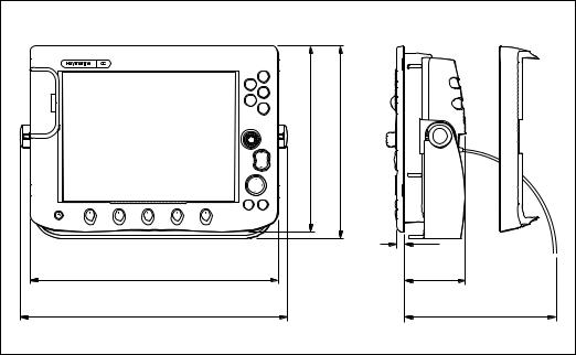
Dimensions
The dimensions for your C-Series display are:
C70 Display
|
PAGE |
|
|
ACTIVE |
|
|
|
|
WPTS |
in) |
in) |
|
MOB |
||
DATA |
|
||
|
MENU |
(6.96 |
(7.44 |
|
|
||
|
OUT |
177 mm |
189 mm |
|
RANGE |
||
|
IN |
||
|
|
||
OK |
CANCEL |
|
|
|
|
|
9.5 mm |
|
|
|
(0.375 in) |
253 mm (10 in) |
|
|
89.4 mm |
|
|
|
(3.5 in) |
282 mm (11.1 in) |
|
|
220 mm (8.66 in) |
|
|
|
plug clearance |
|
|
|
D6612-1 |
C80 Display
|
PAGE |
|
|
ACTIVE |
|
|
|
|
WPTS |
|
|
|
MOB |
|
|
DATA |
|
in) |
in) |
|
MENU |
||
|
|
||
|
OUT |
212.5 mm (8.4 |
222 mm (8.75 |
|
RANGE |
||
|
IN |
||
|
|
||
OK |
CANCEL |
|
|
|
|
|
9.5 mm |
|
|
|
(0.375 in) |
283 mm (11.14 in) |
|
|
89.3 mm |
|
|
|
|
|
|
|
(3.5 in) |
312 mm (12.3 in) |
|
|
220 mm (8.66 in) |
|
|
|
plug clearance |
|
|
|
D6613-1 |
Chapter 1: Preparation for installation |
7 |
|
|
C120 Display
|
PAGE |
|
|
ACTIVE |
|
|
|
|
WPTS |
|
|
|
MOB |
|
276.66 mm (10.9 in) |
DATA |
|
267 mm (10.5 in) |
|
|
MENU |
||
|
OUT |
||
|
RANGE |
||
|
IN |
||
|
|
||
OK |
CANCEL |
|
|
|
|
|
9.5 mm |
|
|
|
(0.375 in) |
357 mm (14 in) |
|
|
87.9 mm |
|
|
|
(3.46 in) |
385 mm (15.15 in) |
|
|
220 mm (8.66 in) |
|
|
|
plug clearance |
|
|
|
D6611-1 |
Accessories and spares
Raymarine accessories and parts can be obtained from your authorized Raymarine dealer. However, if you are in need of an item not available from the retailer or you are uncertain what item to choose for your Display, please contact Raymarine direct (see page 46). Alternatively, please refer to our website: www.raymarine.com
8 |
C-Series Displays Installation Manual |
|
|
1.2 Planning the installation
This section provides information and advice for planning the installation of your Display.
EMC Installation Guidelines
All Raymarine equipment and accessories are designed to the best industry standards for use in the recreational marine environment.
Their design and manufacture conforms to the appropriate Electromagnetic Compatibility (EMC) standards, but correct installation is required to ensure that performance is not compromised. Although every effort has been taken to ensure that they will perform under all conditions, it is important to understand what factors could affect the operation of the product.
The guidelines given here describe the conditions for optimum EMC performance, but it is recognized that it may not be possible to meet all of these conditions in all situations. To ensure the best possible conditions for EMC performance within the constraints imposed by any location, always ensure the maximum separation possible between different items of electrical equipment.
For optimum EMC performance, it is recommended that wherever possible:
•Raymarine equipment and cables connected to it are:
•At least 3 ft. (1 m) from any equipment transmitting or cables carrying radio signals e.g. VHF radios, cables and antennas. In the case of SSB radios, the distance should be increased to 7 ft. (2 m).
•More than 7 ft. (2 m) from the path of a radar beam. A radar beam can normally be assumed to spread 20 degrees above and below the radiating element.
•The equipment is supplied from a separate battery from that used for engine start. Voltage drops below 10 V, and starter motor transients, can cause the equipment to reset. This will not damage the equipment, but may cause the loss of some information and may change the operating mode.
•Raymarine specified cables are used. Cutting and rejoining these cables can compromise EMC performance and must be avoided unless doing so is detailed in the installation manual.
•If a suppression ferrite is attached to a cable, this ferrite should not be removed. If the ferrite needs to be removed during installation it must be reassembled in the same position.
Chapter 1: Preparation for installation |
9 |
|
|
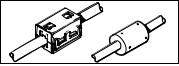
Suppression Ferrites
D6626-1 |
The illustration shows typical cable suppression ferrites used with Raymarine equipment. Always use the ferrites supplied by Raymarine.
Connections to other equipment
If your Raymarine equipment is to be connected to other equipment using a cable not supplied by Raymarine, a suppression ferrite MUST always be attached to the cable near to the Raymarine unit.
Where should the Display unit be located?
Your C-Series display can either be flush-mounted or mounted using the trunnion bracket supplied.
Before you install the display, plan its installation, considering:
•Convenience: The contrast and colors seen on all Liquid Crystal Displays (LCD) vary slightly with viewing angle and are best viewed perpendicular to the display. The mounting location should be easily accessible to allow operation of the front panel controls. Avoid installing where excessive reflection will occur in normal use.
•Access: There must be sufficient space behind the display to allow cable connections to the rear panel connectors, avoiding tight bends in the cables.
•Interference: The selected location should be far enough away from devices that may cause interference, such as motors, generators and radio transmitters/receivers (see EMC Guidelines).
•Magnetic compass: Mount the display at least 3ft (1m) away from a magnetic compass.
•Cable runs: The display should be mounted as near as possible to a Direct Current (DC) power source. All cables should be adequately secured, protected from physical damage and excessive vibration. Avoid running cables through bilges or doorways, or close to moving or hot objects.
•Environmental: The display should be protected from physical damage and excessive vibration. Although the display unit is waterproof, it is good practice to mount it in a protected area away from prolonged and direct exposure to rain and salt spray. The rear of the display should be in a well ventilated space to ensure air circulation to the rear of the unit.
EMC Conformance
Always check the installation before going to sea to make sure that it is not affected by radio transmissions, engine starting etc.
10 |
C-Series Displays Installation Manual |
|
|
Chapter 2: System Integration |
11 |
|
|
Chapter 2: System Integration
2.1 Introduction
This chapter provides an overview of system integration, you may find that your system does not use all the protocols or contain all the instrumentation that is described in it. However it is hoped that the information supplied will help in your understanding of how systems can be integrated and used successfully.
2.2 What is System Integration?
System integration enables various instruments and displays to communicate with each other and use the collected data to increase the functionality of the system.
This data exchange is only possible if the data gathering is accurate, and transfer between instruments is fast and accurate.
Fast and accurate data transfer is achieved by using a combination of the following data protocols:
•SeaTalk.
•SeaTalk2.
•National Marine Electronics Association (NMEA)0183.
•NMEA 2000.
What is SeaTalk?
SeaTalk
The SeaTalk protocol enables compatible instruments to be connected by a single cable carrying power (12 volts, 150 mA) and data in/out, without a central processor.
Additional instruments and functions can be added to a SeaTalk system, simply by plugging them into the network. SeaTalk equipment can also communicate with other non-SeaTalk equipment via the NMEA 0183 standard, provided a suitable interface is used.
SeaTalk2
SeaTalk2 is an enhanced replacement for SeaTalk and is a proprietary extension to
NMEA 2000 and the proven CAN bus technology. It enables other Raymarine SeaTalk2 devices to talk to each other, whilst maintaining near transparent NMEA 2000 compatibility.
 Loading...