


c70

C-Series Display
Reference Manual
Document number: 81221_4
Date: March 2006

E-Series Reference Manual
Trademarks and registered trademarks
Autohelm, HSB, Raymarine, RayTech Navigator, Sail Pilot, SeaTalk and Sportpilot are registered
trademarks of Raymarine Limited. Apelco is a registered trademark of Raymarine Holdings Limited
(registered in all major marketing territories).
AST, Autoadapt, Auto GST, Autoseastate, Autotrim, Bidata, Marine Intelligence, Maxiview, On Board,
Raychart, Raynav, Raypilot, Raystar, ST40, ST60, Seaclutter, Smart Route, Tridata and Waypoint
Navigation are trademarks of Raymarine Limited.
Navionics is a registered trademark of Navionics Company, Italy.
All other product names are trademarks or registered trademarks of their respective owners.
Software in this product is based in part on the work of the Independent JPEG Group.
Contents of this handbook ©Raymarine UK 2006.
Important information i
Important Information
Intended use
The display units detailed in this handbook may form part of marine navigational radar
system or GPS system intended for use on (non-IMO/SOLAS class) leisure vessels or
small workboats.
This handbook contains important information on the operation and maintenance of
your C-Series Display. To get the best results in operation and performance, please take
the time to read this handbook thoroughly.
For full details of installation and system integration, please refer to the C-Series
Installation Guide supplied with the display.
Safety notices
WARNING:Navigation Aid
This device is intended to be used as an aid to navigation. Its
accuracy can be affected by many factors, including equipment
failure or defects, environmental conditions and incorrect
handling or use. It is the user’s responsibility to exercise common
prudence and navigational judgement. This device should not be
relied upon as a substitute for such prudence and judgement.
WARNING:Product installation
This equipment must be installed in accordance with the
instructions in the C-Series System Installation Guide. Failure to do
so could result in poor product performance, personal injury and/
or damage to the vessel.
WARNING:High voltage
The display unit and scanner unit contain high voltages.
Adjustments require specialized service procedures and tools only
available to qualified service technicians - there are no user
serviceable parts or adjustments. The operator should never
remove the display unit cover or attempt to service the
equipment.
WARNING:Electromagnetic energy
The radar scanner transmits electromagnetic energy. Ensure that
the scanner has been installed according to the recommendations
given in the relevant scanner handbook. Avoid looking directly at
the antenna.

ii C-Series Display Reference Manual
WARNING:Fishfinder sounder module
Removing the transducer cable from the rear of the fishfinder
sounder module whilst it is switched on can cause sparks. Only
remove the transducer cable after power has been switched off.
Ensure that the sounder module is mounted where it is well
ventilated and in an area free from flammable vapors.
CAUTION: Water Ingress
To prevent the ingress of water and consequent damage to the display,
ensure that the chart card door is firmly closed. This can be confirmed by an
audible click.
CAUTION: CompactFlash Cards
• Removing the CompactFlash card whilst information is being written to or
read from it may cause damage to the card and loss of all data. Use the
proper procedure detailed on
• Do not save data (waypoints, routes etc.) to a Navionics card as the charts
may be overwritten. When archiving use a different CompactFlash card.
• DO NOT use a metallic instrument such as a screwdriver or pliers to help you
remove a card, as doing this can cause irreparable damage.
page 18
to remove the card.
CAUTION: Global Positioning System Antenna
Do not connect or disconnect the GPS antenna from the display unit whilst
power is switched on. Doing this may result in irreparable damage.
CAUTION: UV Light
To provide protection against the damaging effects of UV light, it is advisable
to replace the sun cover provided when the display is not in use.
CAUTION: Cleaning the display
Take care when cleaning the display, to avoid damaging it:
(1) Do NOT wipe the display screen with a dry cloth, as this could scratch
(2) Do NOT use acid, ammonia based or abrasive products.
Disclaimers
Electronic charts are an aid to navigation designed to facilitate the use of authorized
government charts, not to replace them. Only official government charts and notices to
mariners contain the current information needed for safe navigation. The Captain is
responsible for their prudent use. The C-Series and its charts do not therefore exclude
the user from carrying the required official charts and documents.
Raymarine does not warrant that this product is error-free or that it is compatible with
products manufactured by any person or entity other than Raymarine.
the screen coating.
This product uses digital chart data, and electronic information from the Global
Positioning System (GPS) which may contain errors. Raymarine does not warrant the
accuracy of such information and you are advised that errors in such information may
cause the product to malfunction. Raymarine is not responsible for damages or injuries
caused by your use or inability to use the product, by the interaction of the product with

Important information iii
products manufactured by others, or by errors in chart data or information utilized by
the product and supplied by third parties.
About this manual
This manual describes how to operate your C-Series display in conjunction with
Navionics cartography. It assumes that all peripheral equipment to be operated with it
is compatible and has been correctly installed.
This manual is intended for users of varying marine abilities, but assumes a general
level of knowledge of display use, nautical terminology and practices.
Technical accuracy
To the best of our knowledge, the technical information contained within this
handbook, was correct at the time of printing. However, Raymarine cannot accept
liability for any inaccuracies or omissions it may contain.
In addition, Raymarine’s policy of continuous product improvement may change
specifications without notice. As a result Raymarine cannot accept liability for any
differences between the product and this handbook.
Raymarine does not support after-sales or technical support for Navionics chart cards.
If you wish to file a report of an error or omission on a Navionics chart, please provide
the information to the Navionics web site at the link below:
http://www.navionics.com/DiscrepancyReports.asp
Raymarine does not necessarily support all the features in particular Navionics
cartography.
EMC conformance
All Raymarine equipment and accessories are designed to the best industry standards
for use in the recreational marine environment. Their design and manufacture
conforms to the appropriate Electromagnetic Compatibility (EMC) standards, but
correct installation is required to ensure that performance is not compromised.
Multi-media chart cards
To use your C-Series Display as a navigation aid, charts with the appropriate level of
detail for the geographic area you wish to navigate are required. The charts are
available in electronic format on Navionics Chart cards.
To check the current availability of Navionics® chart card types and the latest feature
sets, visit www.navionics.com or www.navionics.it.
To obtain Navionics cards, contact your local dealer or visit the Navionics web site.

iv C-Series Display Reference Manual
Alternatively, anywhere in North America call Navionics toll-free on 1-800-848-5896
Outside of North America, contact your local dealer or Navionics SpA on:
Phone: (+39) 0584 961696 or Fax: (+39) 0584 961309)
When archiving data, Raymarine recommends that you only use SanDisk CF memory
cards. Other brands of CF memory card may not work in your C-Series Display.
Disposal
Waste Electrical and Electronic Equipment (WEEE) Directive
The WEEE Directive requires the recycling of waste electrical and electronic
equipment. Whilst the WEEE Directive does not apply to some of Raymarine’s
products, we support its requirements as part of our environmental policy and
we ask you to be aware of how you should dispose of this product.
The crossed-out wheelie bin symbol found on our products signifies that it should not
be disposed of in general waste or landfill.
Please contact your local dealer, national distributor or Raymarine Technical Services
for information on product disposal.

Contents v
Contents
Chapter 1: Overview ..................................................................................................1
1.1 What will my C-Series integrate with? .................................................................. 1
1.2 What can the C-Series Display do? ........................................................................ 2
1.3 The Simulator ........................................................................................................ 4
Chapter 2: General Operation ..................................................................................5
2.1 Introduction .......................................................................................................... 5
2.2 Powering the display ON/OFF ...............................................................................5
2.3 Using the controls .................................................................................................6
The control panel ............................................................................................ 6
Buttons and soft keys ...................................................................................... 7
The cursor ....................................................................................................... 8
2.4 Displaying applications ......................................................................................... 8
2.5 Additional screen information ..............................................................................9
2.6 Initial setup procedures ......................................................................................13
Setting the language, date/time format and units of measurement ..............13
Selecting a page set ......................................................................................14
Selecting an application page ....................................................................... 14
Selecting an application window .................................................................. 15
Adjusting the display lighting ........................................................................ 16
2.7 Using CompactFlash cards .................................................................................. 17
Cautions ........................................................................................................ 17
What are CompactFlash cards used for? .......................................................17
Inserting a card .............................................................................................18
Removing a card ...........................................................................................18
2.8 Managing data ...................................................................................................19
Writing/retrieving data to a CompactFlash card ............................................19
Sending and receiving information using a PC ..............................................22
Password protecting your waypoints ............................................................ 23
2.9 Emergencies and warnings .................................................................................26
Man Overboard (MOB) ................................................................................. 26
Alarms ..........................................................................................................27

vi C-Series Display Reference Manual
Chapter 3: Working with Waypoints .....................................................................29
3.1 What is a waypoint? ........................................................................................... 29
3.2 How are waypoints represented? .......................................................................30
3.3 Placing a waypoint ............................................................................................. 31
3.4 Navigating to a waypoint ................................................................................... 32
Start navigating to a waypoint ...................................................................... 32
Stop navigating to a waypoint ......................................................................33
3.5 Viewing waypoint information ........................................................................... 33
3.6 Editing a waypoint ..............................................................................................34
Changing waypoint details ...........................................................................35
Moving a waypoint ....................................................................................... 35
Erasing a waypoint(s) .................................................................................... 36
Changing the default symbol or group ..........................................................37
3.7 Sorting the waypoint list ..................................................................................... 38
3.8 Organising waypoints into groups ...................................................................... 38
Displaying the waypoint group list ................................................................ 38
Making a new waypoint group .....................................................................39
Moving waypoints between groups ..............................................................39
Renaming an existing group .........................................................................40
Erasing a group ............................................................................................. 41
3.9 Controlling waypoint display .............................................................................. 41
Show/hide waypoint names ..........................................................................41
Showing/hiding waypoint symbols ...............................................................42
Showing/hiding waypoint groups ................................................................. 42
Chapter 4: Using the Chart ......................................................................................43
4.1 Important ...........................................................................................................43
Safety ............................................................................................................43
Chart functionality ........................................................................................43
Chart cards .................................................................................................... 44
4.2 Uses of the chart application .............................................................................. 44
4.3 Viewing the chart ................................................................................................ 45
4.4 The chart display ................................................................................................. 45
4.5 Where am I on the chart? .................................................................................... 46
4.6 Moving around the chart .................................................................................... 46
4.7 Additional information on the chart ................................................................... 47

Contents vii
Displaying details of objects and features .....................................................48
Finding nearby features and services ............................................................48
Displaying details of tides ............................................................................. 49
Displaying details of currents ........................................................................ 50
Displaying details of port services ................................................................. 50
Displaying details of business services & points of interest ...........................53
Displaying vessel identity (AIS) ..................................................................... 54
4.8 Measuring distances and bearings .....................................................................55
... from your boat ...........................................................................................55
... between two points on your chart ............................................................. 55
4.9 Navigating to a specific point ............................................................................. 56
Go to an existing waypoint ........................................................................... 57
Resetting cross track error (XTE) ................................................................... 57
Arriving at your target waypoint ................................................................... 57
Stop navigating to your target waypoint .......................................................58
Maintaining a view of your navigation ..........................................................58
4.10 Building and following a route ............................................................................ 59
What is a route? ............................................................................................ 59
What can I do with a route? .......................................................................... 59
Building a route ............................................................................................. 60
Following a route ..........................................................................................64
Resetting cross track error (XTE) ................................................................... 66
Viewing details of routes ...............................................................................67
4.11 Editing routes ..................................................................................................... 68
Selecting a route for editing .......................................................................... 68
Editing the selected route .............................................................................69
4.12 Monitoring where you are going ........................................................................ 74
... using chart vectors .................................................................................... 74
... using the Course Deviation Indicator (CDI) ................................................75
4.13 Warnings of potential dangers ............................................................................75
4.14 Using the radar with the chart ............................................................................76
Synchronizing the chart with radar range ..................................................... 76
Viewing MARPA targets on the chart ............................................................76
Distinguishing between fixed and moving objects ........................................77
4.15 Recording where you have been ......................................................................... 78
What is a track? ............................................................................................ 78
How can I use tracks? ....................................................................................79

viii C-Series Display Reference Manual
Creating a track ............................................................................................. 79
Creating a route from a track ........................................................................80
4.16 Editing tracks ...................................................................................................... 81
Selecting a track for editing ........................................................................... 81
Editing the selected track .............................................................................. 82
4.17 Defining how the chart windows are presented ................................................. 83
Working with multiple chart views ................................................................ 83
Setting the orientation of the chart ...............................................................84
Setting the motion mode .............................................................................. 85
4.18 Altering the level of chart detail displayed ..........................................................86
Showing or hiding waypoints/waypoint information ....................................87
Showing or hiding a route or a track ............................................................. 88
Showing or hiding cartographic features ...................................................... 89
4.19 Setting up your chart and its cartography ...........................................................90
Chart Setup ...................................................................................................90
Cartography Setup ........................................................................................ 93
Chapter 5: Using the Fishfinder ..............................................................................95
5.1 Introduction ........................................................................................................95
5.2 How does the Fishfinder work? ........................................................................... 95
5.3 What can the fishfinder show me? ...................................................................... 96
Interpreting the bottom structure ................................................................. 97
Factors influencing target display .................................................................. 97
Factors impairing a fishfinder picture ............................................................ 98
Seeing a live image .......................................................................................98
5.4 Enhancing what you see ................................................................................... 100
Changing the range .................................................................................... 100
Shifting the image .......................................................................................100
Zooming in on the bottom ...........................................................................101
Simplifying the bottom image .....................................................................103
Isolating bottom fish ...................................................................................104
Changing how the image scrolls ................................................................. 105
Changing how the depth digit is displayed ................................................. 106
5.5 Marking a position ............................................................................................107
5.6 Determining depths and distances of targets ....................................................108
Measuring using VRMs ...............................................................................109
5.7 Fishfinder alarms .............................................................................................. 110

Contents ix
5.8 Setting up your fishfinder ..................................................................................110
Display settings ...........................................................................................111
Transducer Calibration ................................................................................ 112
DSM Setup ..................................................................................................113
5.9 Other settings affecting the fishfinder image ....................................................114
Operating frequency modes ........................................................................114
Gain modes .................................................................................................115
Adjusting the power setting ........................................................................ 117
Chapter 6: Using the Radar ...................................................................................119
6.1 Introduction ......................................................................................................119
6.2 What is radar? ..................................................................................................119
Detecting targets ........................................................................................ 119
Maximum radar range ................................................................................120
Factors impairing a radar picture .................................................................120
6.3 Powering on/off the various scanner operating modes .....................................124
6.4 The radar picture ............................................................................................... 125
6.5 Marking a position on the radar screen ............................................................ 126
6.6 Changing what you see in the radar window ....................................................126
Setting the orientation of the radar .............................................................126
Setting the motion mode ............................................................................ 128
Showing or hiding the range rings .............................................................. 130
Changing the bearing mode for EBLs ..........................................................130
6.7 Getting the best picture ....................................................................................130
Using the GAIN functions ............................................................................ 130
Using the enhance echoes functions ...........................................................132
6.8 Changing the displayed range ..........................................................................135
Radar range and chart scale synchronization ..............................................135
6.9 Measuring distances, ranges and bearings .......................................................136
... Using the range rings ..............................................................................136
... Using the cursor ......................................................................................136
... Using VRMs and EBLs .............................................................................. 137
... Using floating VRMs/EBLs .......................................................................139
6.10 Using radar to avoid a collision ......................................................................... 140
Guard Zones ...............................................................................................140
MARPA .......................................................................................................143
Setting up MARPA ....................................................................................... 146

x C-Series Display Reference Manual
Acquiring a target to track ..........................................................................147
Cancelling targets .......................................................................................147
Displaying vessel identity (AIS) ................................................................... 148
6.11 Setting up your radar ........................................................................................ 148
6.12 Warnings of potential dangers ..........................................................................150
Chapter 7: Using the data application ................................................................151
7.1 Introduction ......................................................................................................151
7.2 Selecting a data application .............................................................................. 151
7.3 Selecting the data for display ............................................................................152
Pre-configured data panels ......................................................................... 152
Customize the panels ..................................................................................153
Chapter 8: Using the Course Deviation Indicator ..............................................157
8.1 Introduction ......................................................................................................157
8.2 The CDI screen .................................................................................................. 157
Steering instructions ................................................................................... 158
8.3 Selecting the CDI application ............................................................................ 158
8.4 Modifying the CDI application .......................................................................... 158
Chapter 9: Using the Engine Monitor ..................................................................159
9.1 Introduction ......................................................................................................159
9.2 Displaying and setting up the engine monitor ..................................................159
9.3 The engine monitor display ...............................................................................161
9.4 Configuring the engine panels. .........................................................................161
9.5 What should I do when an alarm is triggered? ..................................................161
Chapter 10: Navtex ..................................................................................................163
10.1 Overview ..........................................................................................................163
10.2 Setting up Navtex weather ...............................................................................163
10.3 Incoming message alerts ..................................................................................163
10.4 Viewing messages ............................................................................................ 164
Displaying the Navtex Message List ............................................................164
Displaying and scrolling through a message ............................................... 164
10.5 Managing Navtex messages ............................................................................ 164
Selecting message alert categories ............................................................. 164
Sorting the message list ..............................................................................165

Contents xi
Chapter 11: Automatic Identification System (AIS) ............................................167
11.1 Introduction ......................................................................................................167
11.2 What is AIS? .....................................................................................................167
Classes of AIS data ......................................................................................167
11.3 What do I need to run AIS? ...............................................................................169
11.4 Selecting the AIS function ................................................................................. 169
AIS status ....................................................................................................169
11.5 How is AIS data displayed? ...............................................................................170
AIS Target symbols ......................................................................................170
Viewing target information .........................................................................171
11.6 Using AIS for collision avoidance ......................................................................173
Safe zones ...................................................................................................173
MARPA and AIS options .............................................................................. 174
Safety messages ......................................................................................... 174
11.7 AIS Alarms ........................................................................................................174
Local AIS alarms ..........................................................................................175
Active alarm list ..........................................................................................175
11.8 Simulator ..........................................................................................................176
11.9 AIS Layer Setup Menu ....................................................................................... 176
Chapter 12: System setup and customizing .........................................................177
12.1 Customizing the page sets ................................................................................ 177
Reconfiguring the application and page layout ...........................................177
Rename a page set ...................................................................................... 178
Return to default setting ............................................................................. 178
12.2 Changing the databar .......................................................................................179
Databar position .........................................................................................179
Data bar size ............................................................................................... 179
Customizing the contents of the data bar ................................................... 180
12.3 Changing the set up menu options ................................................................... 183
Application specific ..................................................................................... 183
External equipment menus ......................................................................... 183
System-wide menus ....................................................................................183
Chapter 13: Maintenance & Troubleshooting ......................................................193
13.1 Introduction ......................................................................................................193
13.2 Maintenance procedures ..................................................................................193

xii C-Series Display Reference Manual
Servicing and Safety ....................................................................................193
Routine checks ............................................................................................193
Cleaning the display .................................................................................... 194
13.3 Resetting the Display ........................................................................................ 194
Settings reset .............................................................................................. 194
Settings and data reset ............................................................................... 195
13.4 Troubleshooting your Display ........................................................................... 195
Common problems and how to solve them .................................................195
13.5 Getting Technical Support .................................................................................198
World wide web ..........................................................................................199
Contacting Raymarine in the US ..................................................................199
Contacting Raymarine in Europe .................................................................200
For Navionics cartography ..........................................................................201
AppendixA: Specification ..................................................................................... 203
AppendixB: List of Abbreviations ....................................................................... 209
AppendixC: List of cursor labels .......................................................................... 211
Chapter 1: Overview 1
Chapter 1: Overview
This chapter gives an overview of the C-Series display system and its features.
1.1 What will my C-Series integrate with?
Autopilot
Instruments
AIS receiver
GPS
Remote keyboard
Fishfinder DSM 250
C-Series display
PAGE
ACTIVE
WPTS
MOB
DATA
MENU
OUT
RANGE
IN
CANCELOK
Navtex receiver
Radar scanner
D9001_1
DSC VHF
11.18.02
RAY240
OK
MENU
CH
16/9
HI/LO
WX
SCAN WATCH
SQ
When used as part of a SeaTalk system it will display information from other SeaTalk
and NMEA instruments. Information from the C-Series display can be transferred
between applications and to other SeaTalk instruments within the system. For more
detail on system integration, please refer to the Installation Guide.
2 C-Series Display Reference Manual
1.2 What can the C-Series Display do?
With the appropriate equipment connected to your system and the necessary data
available, your C-Series display combines the following applications which are used to:
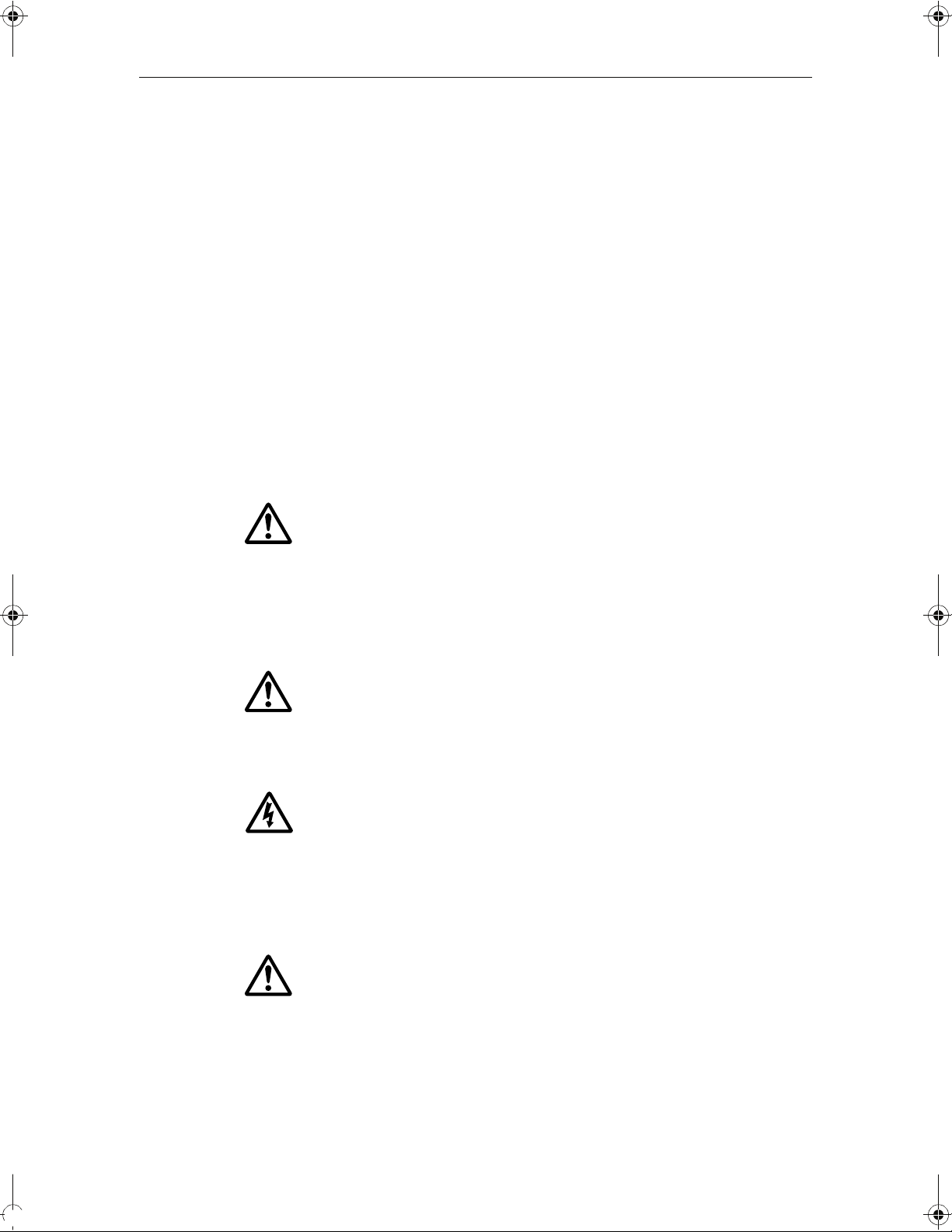
Chart (Chapter 4)
0.5nm North-Up (Relative Motion) Local
You will need a chart card, and position/heading data, for the chart application to be
fully functional.
Locate where you are.
Interpret your surroundings.
Monitor where you are going.
Record where you have been.
Navigate to a specified position (waypoint).
Build and navigate routes.
View details of nearby features & services.
View details of boats equipped with AIS.
Distinguish between fixed and moving objects.
Measure distances and bearings.
D7363_2
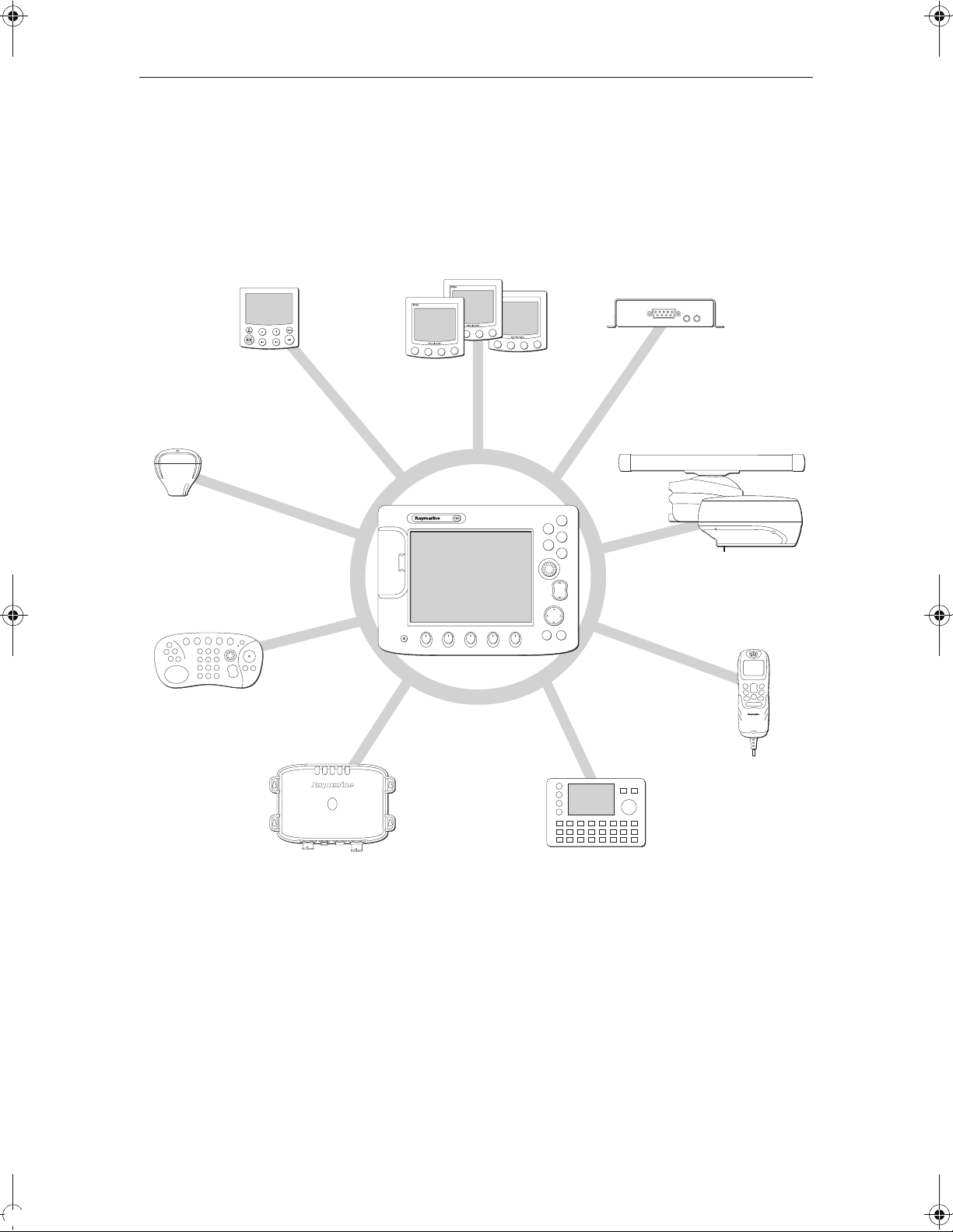
Fishfinder (Chapter 5)
200kHz: Auto Range: Auto
Build a picture of what is below your vessel.
Locate & distinguish underwater objects & targets.
Distinguish the seabed and its texture.
Obtain information about water depth, temperature.
Mark a point of interest, fishing spot etc.
TRANSDUCER
SETTINGS…
ZOOM… BOTTOM LOCK… A-SCOPE… PRESENTATION…
Determine depths and distances of targets.
You will need position data, in addition to a DSM250, for your fishfinder to be fully
functional.
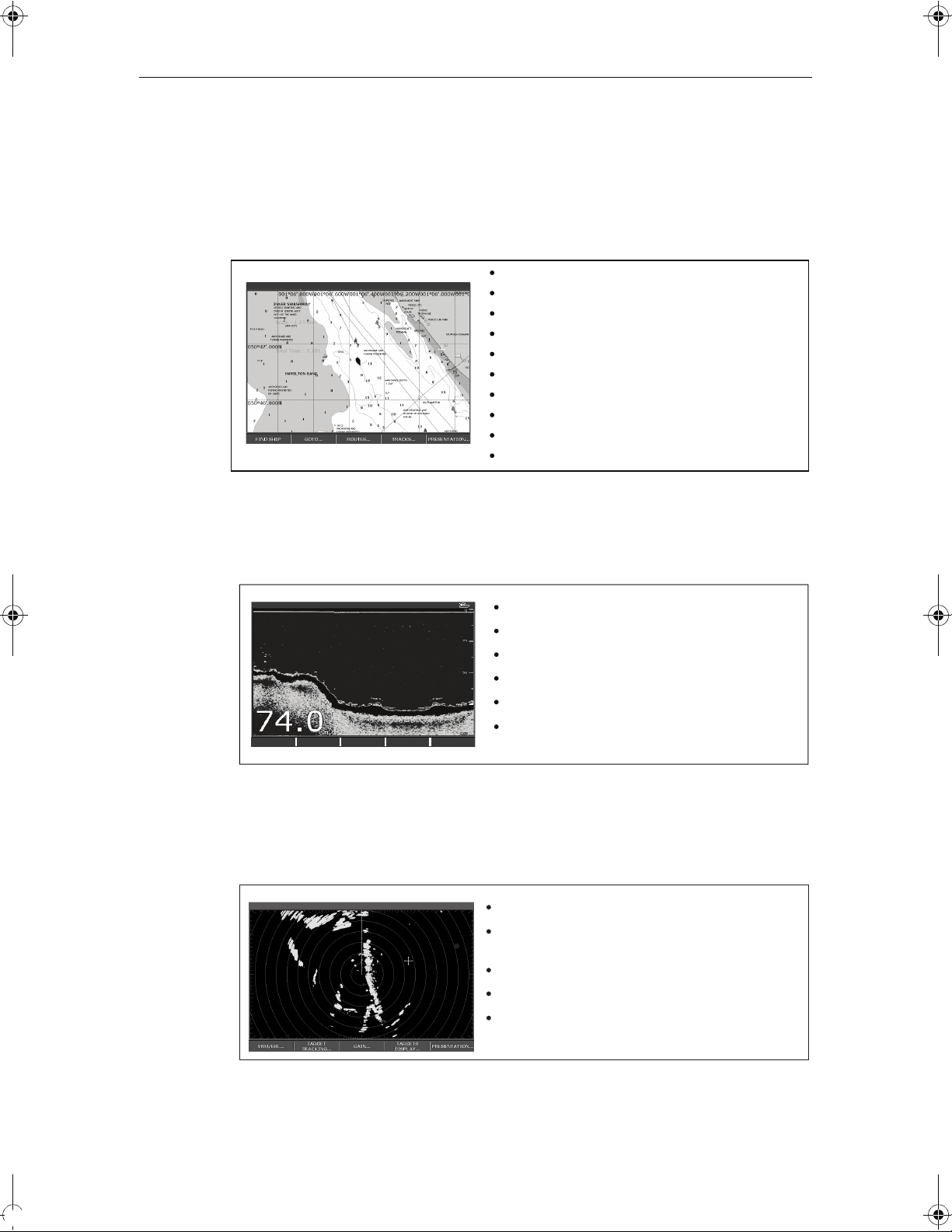
Radar (Chapter 6)
6nm North-Up (Relative Motion) Rings 1nm
TARGET
VRM/EBL... GAIN...
TRACKING...
TARGETS
DISPLAY...
PRESENTATION...
Detect landmasses & navigation markers.
Detect and measure the range and distance of other
vessels.
Acquire targets and track them for collision avoidance.
Navigate to a specified position (waypoint).
View details of boats equipped with AIS.
D7377-1
D7375-2
You will need position and heading data, in addition to a compatible scanner, for your
radar application to be fully functional.
Chapter 1: Overview 3
Data (Chapter 7)
View data generated by the system or by instruments
available on NMEA 0183, NMEA 2000 and SeaTalk or
2
.
SeaTalk
Course Deviation Indicator (Chapter 8)
3nm North-Up Relative Motion Local
View real-time display of your vessel on a 'rolling
road' in 3D perspective.
Give details of any correction required to steer your
vessel along a given course.
View data about the distance and time to go until
you reach a specified point.
D7376-1
You will need accurate heading and position data for your CDI application to be fully
functional.
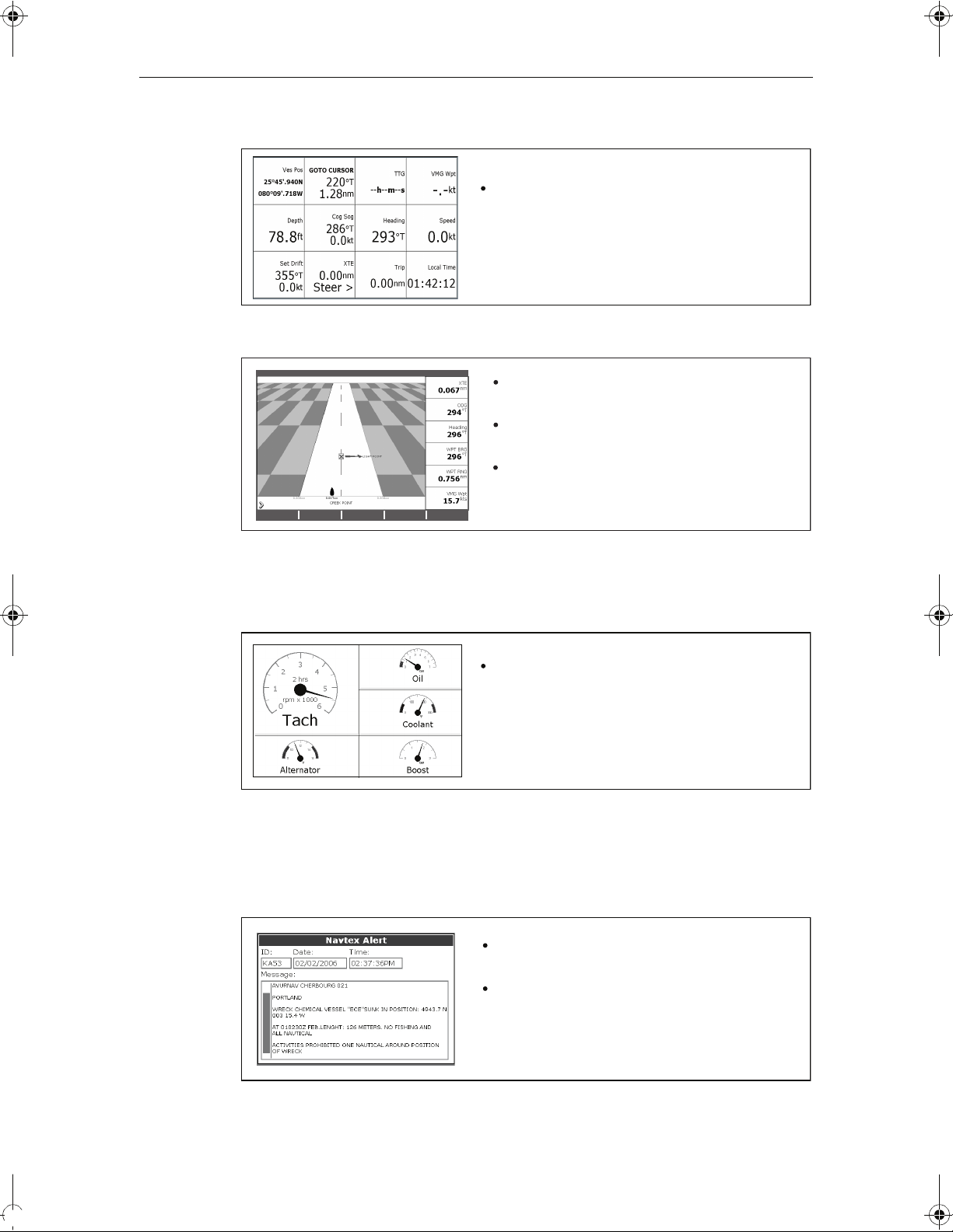
Engine Monitor (Chapter 9)
T
View engine data e.g. engine temperature, oil pressure,
fuel level etc from up to three engines on a compatible
engine system.
Navtex (Chapter 10)
Major areas of NAVTEX coverage include the Mediterranean Sea, the North Sea,
coastal areas around Japan and areas around the North American continent.
Automatic broadcast of localised Maritime Safety
Information (MSI)
Draft
Receive navigational and meteorological warnings, and
search and rescue information.
D7379-1
D7497-1
You will need a Navtex receiver connected to your system via NMEA, in order to receive
this data.
D8728-1

4 C-Series Display Reference Manual
Waypoints (Chapter 3) & AIS (Chapter 11)
Whilst not applications in their own right, waypoints and AIS are handled at system
level and are covered in separate chapters.
1.3 The Simulator
The C-Series Display includes a simulator mode, which allows you to practice
operating your display without data from a GPS antenna, radar scanner, fishfinder or
AIS receiver. The simulator mode is switched on/off in the System Setup Menu (see
page 183
• Before installation - Simply connect the display to a 12V DC power supply,
• After installation - Whilst in a marina or at anchor.
Please note that system settings made whilst in simulator mode, are not transmitted
via SeaTalk to other equipment.
). Once enabled, you can use the simulator:
fused at 1 amp by attaching the red core from the power lead to positive (+) and
the black core to negative (-).
Important: Incoming AIS safety messages cannot be displayed while the simulator is
switched on.
Chapter 2: General Operation 5
Chapter 2: General Operation
2.1 Introduction
This chapter gives details of the general operation of the C-Series display, and covers
the following subjects:
• Powering the display on/off.
• Using the controls.
• Application display.
• Displaying and editing additional information.
• Adjusting the display lighting.
• Initial setup procedures.
• Using CompactFlash cards.
• Managing data.
• Emergencies and warnings.
2.2 Powering the display ON/OFF
Power ON
D6577-1
At this time the radar scanner (if fitted and powered) is checked for compatibility with
the display. An error message is displayed if the scanner is incompatible.
Power OFF
Remember to replace the suncover to protect the display.
Press the POWER button until the introductory logo is displayed. The keys
light up and after a few seconds an application page and a navigation
warning is displayed. Read this information and then press OK to remove it.
Press and hold the POWER button until the power down count reaches
zero. If the POWER button is released within the countdown period, power
off is cancelled.
6 C-Series Display Reference Manual
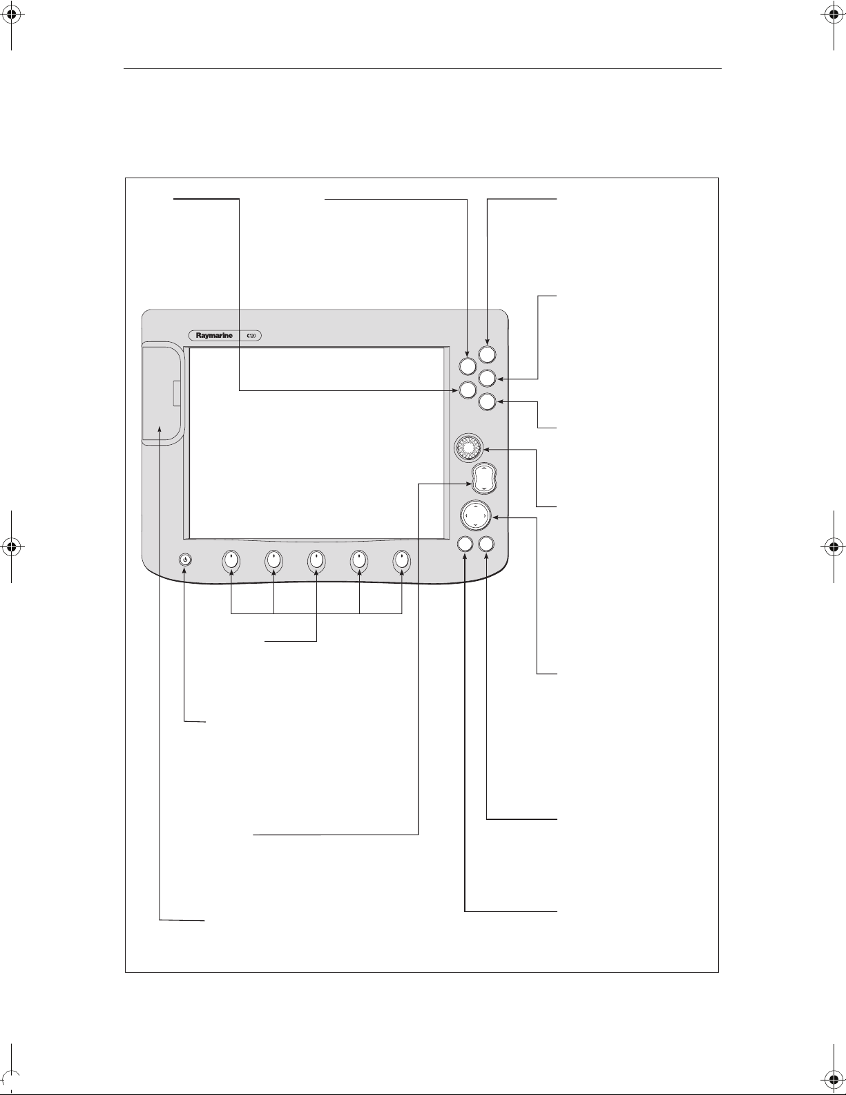
2.3 Using the controls
The control panel
DATA
Press to access
ruler, chart vectors,
archive & transfer
and data bar
on/off functions.
Softkeys
Press to select the corresponding function identified
by the on-screen label
Power
Press once to turn ON.
Press again to access
backlight functions and
scanner controls.
Press and hold to turn the
display OFF.
RANGE
Press to change the display
scale so that a smaller or
larger area can be seen on
the screen.
Chart Card slot
Open the cover to install
CompactFlash cards.
ACTIVE
When multiple windows are open:
- Press to select required window.
- Press and hold to maximise current
window.
- Press again to return to multiple
windows.
PAGE
Press to scroll through available
pages.
Press and hold to select different
page set or customise your own
layout.
WPTS/MOB
Press to display the waypoint
soft keys.
Press again to place waypoint at
PAGE
ACTIVE
WPTS/
MOB
DATA
MENU
your boat's position.
Press and hold to place a
Man Overboard (MOB)
marker at your current position.
Press and hold again to exit
MENU
Press to access the set up
menus.
OUT
RANGE
IN
Press and hold to access help
information.
Rotary control
Use to edit alpha-numeric
CANCELOK
values, and scroll through lists.
Turn clockwise to increase
value and counter-clockwise to
decrease value.
Press to move the cursor to the
next character when editing
text.
Use to edit symbology (VRM/
EBL etc).
Trackpad
Used to control the on-screen
cursor and to scroll through
menu items.
Press the corresponding edge
of the trackpad to move the
cursor horizontally, vertically or
diagonally.
Press and hold to move rapidly
over larger distances.
CANCEL
Press to cancel the selected
on-screen option when editing
data; also used to return to
the previous soft key set or
menu.
OK
Press to select an on-screen
option, or return to the
previous soft key set or menu.
D7517_1
Chapter 2: General Operation 7
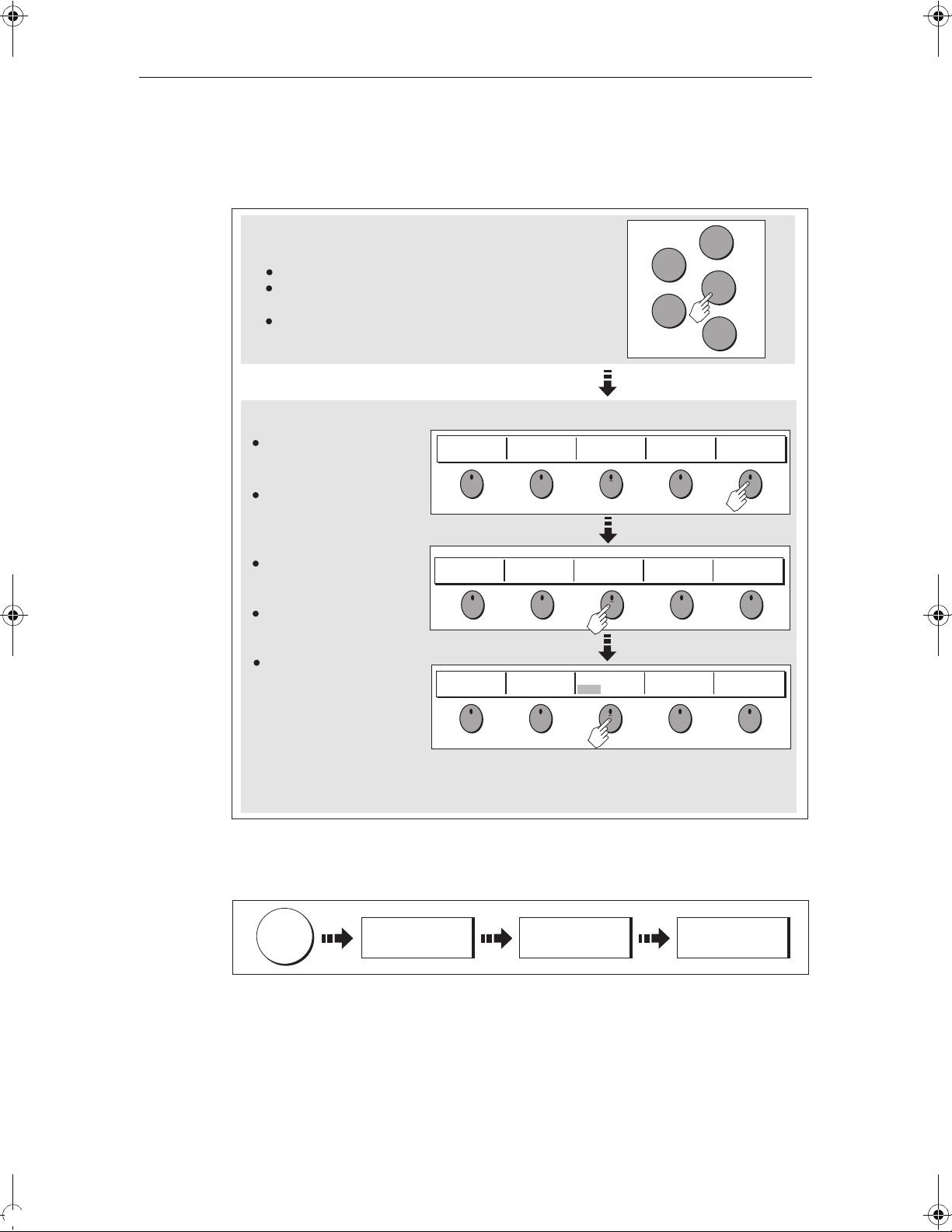
Buttons and soft keys
To navigate to the required function you will need to press a series of buttons and/or
soft keys:
Buttons
Access system functions or change what you see on-screen.
Within the text of this document they are written in bold capitals
e.g. WPTS/MOB.
Press and hold to access short cuts.
Soft keys
They change depending on
application or function
WAYPOINT AT
CURSOR
WAYPOINT AT
VESSEL
being performed.
Press the corresponding key
(below the screen) to select.
Further soft keys may be
displayed.
If a key has several options,
each press will highlight the
ERASE WAYPOINT SORT LIST
next option.
If a key displays a single
value or a slider above, use
the rotary control to adjust.
Within the text of this
document they are written
in capitals e.g. SORT LIST.
WAYPOINT AT
LAT/LONG...
SET DEFAULT SYM
& GROUP...
SET UP DEFAULT
SYMB GROUP
ACTIVE
DATA
GO TO WAYPOINT
OPTIONS…
WAYPOINT
GROUPS...
PAGE
WPTS
MOB
MENU
REVIEW AND EDIT
WAYPOINTS
VIEW AND EDIT
DETAILS…
EDIT DEFAULT
Example:
The example above shows the series of button and soft key presses
required to change the waypoint default symbol or group.
This process of pressing buttons and soft keys to navigate to the required function is
simplified in this manual and represented by a strip e.g.
WPTS
MOB
REVIEW AND EDIT
WAYPOINTS ...
SET DEFAULT SYM
& GROUP...
SET UP DEFAULT
SYMB GROUP
Note: The key beep that you hear whenever a button or soft key is pressed, can be
switched off and the soft keys automatically hidden if required. For more details,
please refer to the Display Setup Menu on page 191.
D7364-2
D7365-2
8 C-Series Display Reference Manual
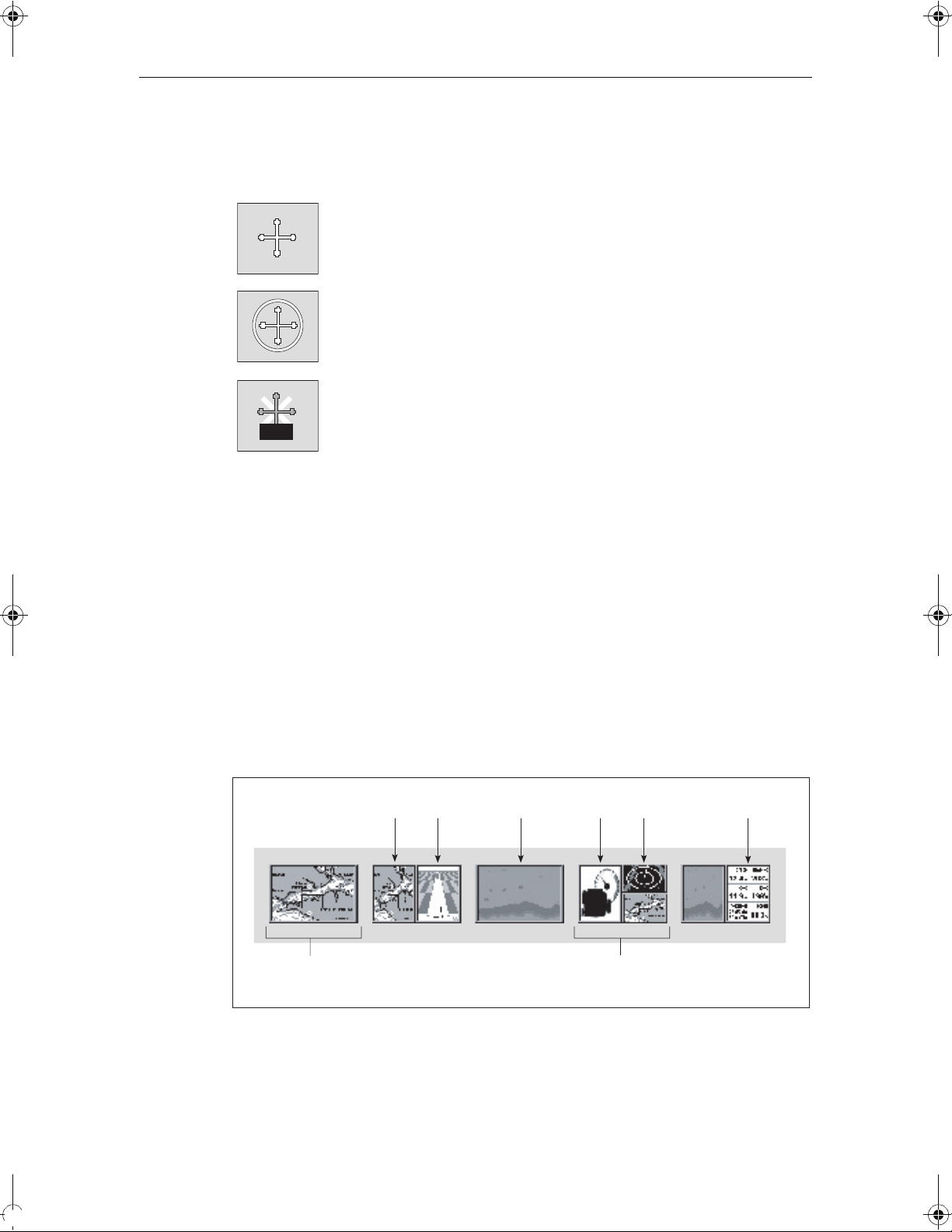
The cursor
When you are using the chart and radar applications, the cursor is used to move
around the screen:
The cursor appears on the screen as a white cross.
D7366_3
If the cursor has not been moved for a short period of time, it changes to
a circle with a cross in it, to make it easier to locate on the screen.
D7368_2
The cursor is context-sensitive - when it is placed over an object e.g. a
waypoint or chart feature, it changes color and a label or information
WPT
Notes: (1) For a full list of cursor labels and their meanings, please see
associated with the object is displayed. When you place the cursor over
D7369-2
certain items, the soft keys change to enable you to access related
operations.
page 211
(2) For details of how to temporarily hide the cursor, please see
page 191.
2.4 Displaying applications
The various applications that make up your C-Series system are displayed in a series of
screens known as
page sets
choose from. Each page set contains 5
windows
Page set
combined in various formats. Each window can display an application e.g.
Page
(consists of 1, 2,
3 or 4 windows)
. There are 4 pre-configured and one empty page set to
CDIChart
pages
. These pages are made up of 1, 2, 3 or 4
Fishfinder
Engine
monitor
Radar
Window
Data
D8928_1
If necessary, you can change the combination and layout of these page sets to meet
your particular needs (see
page 177
).
Note: For details of how to select page sets, pages and windows, please refer to
page 14.
Chapter 2: General Operation 9
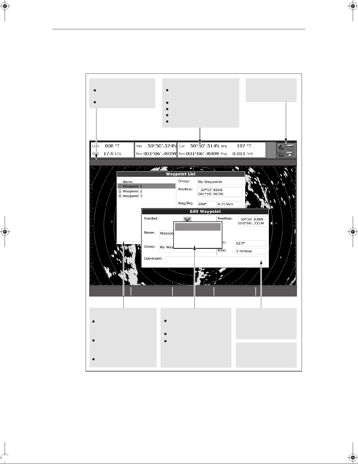
2.5 Additional screen information
Information is displayed on the screen using a variety of methods:
Status bar
Status bar
Gives information specific to
Gives information specific to
each application.
each application.
Cannot be edited or moved.
Cannot be edited or moved.
3nm
3nm
Head-Up Relative Motion Rings ½nm
Head-Up Relative Motion Rings ½nm
Data bar
Data bar
Gives information associated with
Gives information associated with
your boat or the environment.
your boat or the environment.
Customisable content*
Customisable content*
Vertical or horizontal format*
Vertical or horizontal format*
Display or hide*.
Display or hide*.
Normal or large size*.
Normal or large size*.
Status bar
Gives information specific to
each application.
MARPA ALARM
Target lost (on screen)
Target lost (on screen)
Cannot be edited or moved.
MARPA ALARM
Status icons
Status icons
Confirm status of DSM,
Confirm status of DSM,
GPS and scanner.
GPS, AIS and scanner.
ACKNOWLEDGE
ACKNOWLEDGE
Data base lists
Data base lists
Contain information you have
Contain information you
added to the display's memory
have added to the display's
e.g. waypoints.
memory e.g. waypoints.
Highlight an entry using
Highlight an entry with
trackpad or rotary control to
trackpad or rotary control to
display related information.
display related information.
Editable using soft keys.
Editable using soft keys.
* For details of how to adjust and edit the data bar, please see
Pop-up messages
Pop-up messages
Alert you to a situation e.g.
Alert you to a situation e.g.
alarm, function not available.
alarm, function not available.
Not editable.
Not editable.
May require a response e.g.
May require a response e.g.
press ACKNOWLEDGE to
press ACKNOWLEDGE to
silence alarms.
silence alarms.
Dialog boxes
Dialog boxes
Enable data to be edited or
Enable data to be edited or
entered into a store/list e.g.
entered into a store/list
editing a waypoint.
e.g. editing a waypoint.
Menus (see next page)
Menus (see next page)
Used to configure system to
Used to configure system
your particular needs.
to your particular needs.
page 180
Note: To change the size of the text on screen, please see page 191.
D7456_1
D7456_2
10 C-Series Display Reference Manual
C
.
S
N
Safety
ft
t
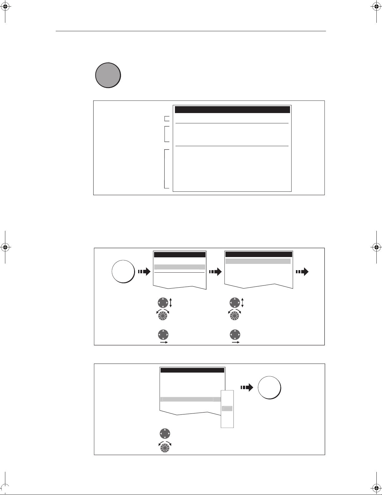
Menus
0
Menus enable you to configure your system to your particular needs.
MENU
MENU
D6582-1
For details of application menus, please refer to the appropriate chapter. For all other
settings, please refer to
To access a menu:
Whenever the MENU button is pressed, the Setup menu is displayed
containing a list of all the menus available for the active application
together with system wide menus e.g.
Setup
Menus for the active
application
External equipment/
instruments
System-wide menus
Radar Setup ...
GPS Status...
Compass Setup...
AIS Layer Status...
System Setup...
Alarm Setup...
Display Setup...
Databar Set...
Select Page Setup...
System Diagnostics...
Remove CF Card
Chapter 12:System setup and customizing
.
D7370_2
1. Select the appropriate menu and setting:
Setup
Chart Setup...
artography Setup..
MENU
GPS Status...
Compass Setup...
1. Highlight item, using:
Trackpad (up/down)
or
Rotary control
2. Select item, using:
Trackpad (right)
2. To change the setting:
Cartography Setup Menu
Chart Display Detailed
Chart Grid On
Chart Text On
Chart Boundary ON
pot Soundings O
Contour 66
Depth Contour ALL
Nav. Marks ON
Highlight or change value to
new setting, using:
Trackpad (up/down)
or
Rotary control
Cartography Setup Menu
Chart Display Detailed
Chart Grid On
Chart Text On
Chart Boundaries ON
Spot Soundings ON
1. Highlight item, using:
Trackpad (up/down)
or
Rotary control
2. Select item, using:
Trackpad (right)
D8500_1
OK
OFF
7ft
10ft
16f
20ft
33ft
66ft
D8501_1
Chapter 2: General Operation 11
1
1
a
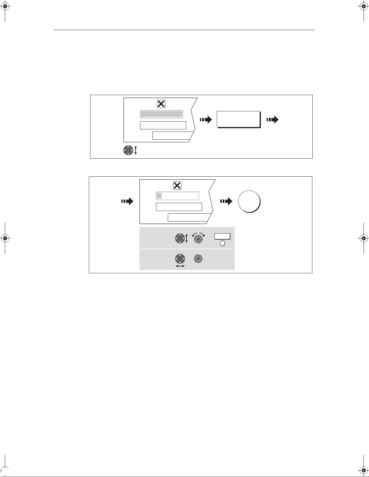
Editing the dialog box information
Dialog boxes enable data to be edited or entered into a list e.g. Edit Waypoint screen.
To edit/enter data into a dialog box:
1. Select the field for editing:
e.g.
Symbol
Name
Waypoint
My Waypoints
Group
Comment
Highlight field to be edited
e.g. waypoint name
2. Edit/enter data and save:
e.g.
Symbol
Name
W
My Waypoints
Group
oint
EDIT NAME
OK
D8502-1
Comment
To change
character or
selection, use:
To move to next
character for
editing, use:
or
or
,
Turn
Press
3. Repeat Steps 1 and 2 if necessary.
Notes: (1) Character text can be entered in upper or lower case. (although the
system is not case sensitive e.g. WAYPOINT 1, Waypoint 1are considered to be the same name).
(2) If you need to use special or accented characters (e.g.
~ ` ´), the
Extended Character Set should be switched to ON in the System
Setup Menu (see page 183).
D8503-1
12 C-Series Display Reference Manual
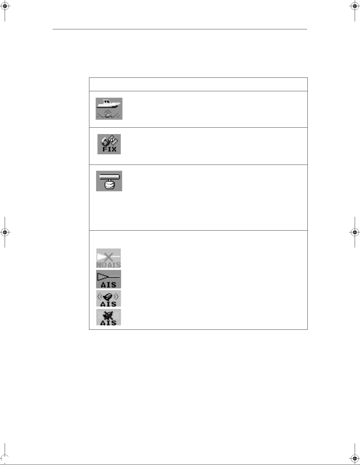
Status icons
The status icons on the data bar confirm whether the appropriate connections to your
C-Series system have been made:
Status icon Description
The boat and fish icon indicates the current status of your fishfinder:
Icon animated - connection to a DSM has been successful.
Icon static - the DSM is connected but not transmitting.
D6892-3
(animated icon)
(static icon)
(static icon)
Icon greyed-out - no DSM is connected.
The satellite icon indicates the current status of your GPS:
FIX - your unit is successfully connected to a GPS receiver.
NO FIX - your unit has been unable to connect to a suitable GPS receiver.
D6893-2
The scanner icon indicates the current status of your radar scanner:
Icon rotates - the scanner is transmitting (TRANSMIT/TX mode).
Icon static - the scanner is powered on but is not currently transmitting
D6894-2
(STANDBY mode).
Icon greyed out - this indicates that the scanner is currently powered
off (OFF mode).
Icon rotates and is then static - a power save mode in which the
scanner powers on/off intermittently (TIMED TRANSMIT mode).
The AIS icon indicates the current status of the AIS function:
AIS unit not available i.e. not connected or off.
AIS unit is switched on and operating.
AIS unit on with active alarms.
AIS unit switched on and operating but dangerous and lost alarm dis-
D8929_1
o
abled.
Note: These icons will also appear when you are in simulator mode.
Chapter 2: General Operation 13
/dd/yy
/dd/yy
2.6 Initial setup procedures
When you first use your C-Series Display after it has been commissioned (see
Installation Guide), we recommend that you carry out the following:
• Set the language, the date and time format and preferred units of measurement.
• Select a page set.
• Select an application page/window.
• Adjust the display lighting.
Note: For full details of all setup and customizing options, please refer to Chapter
12:System setup and customizing.
Setting the language, date/time format and units of measurement
To adjust the language, date/time format and units of measurement to your preferred
settings:
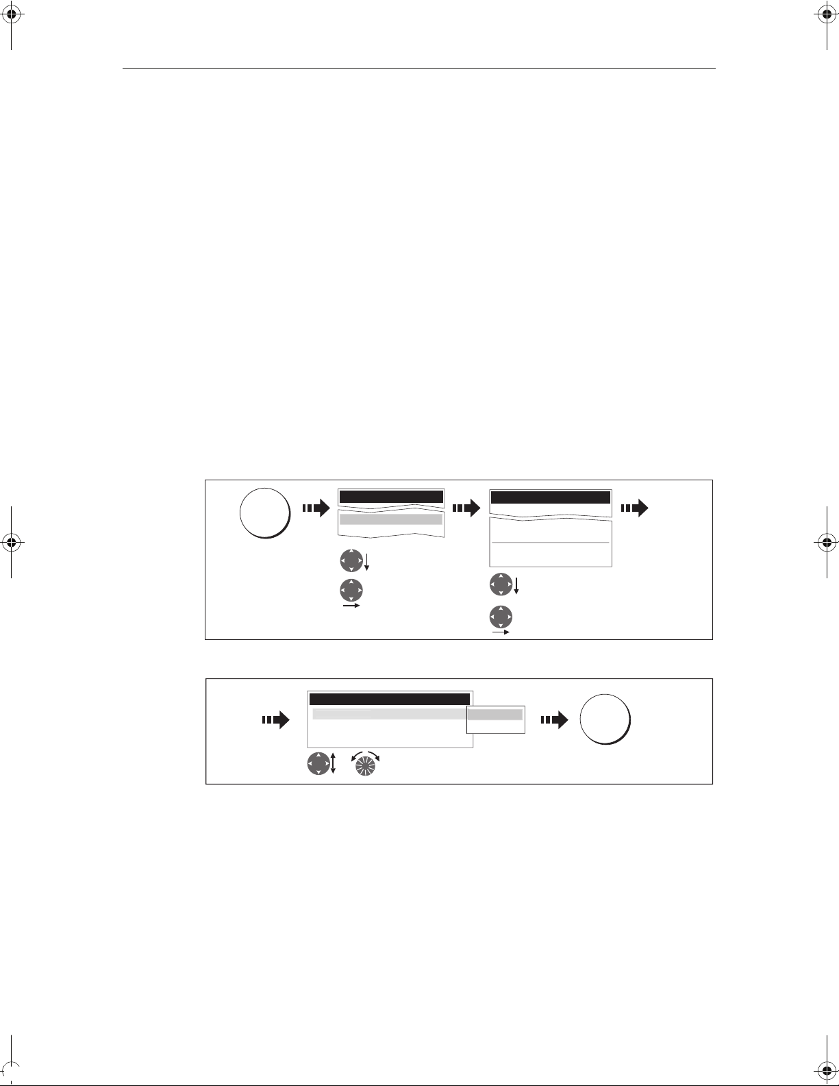
1. Select the setting:
MENU
Setup
System Setup...
Alarm Setup...
Highlight
System Setup
Enter System
Setup
System Setup Menu
Position Made Lat/Lon...
Date/Time Setup...
Units Setup...
System Integration Setup...
Waypoint Password Setup...
Highlight required
setting
Enter setting
2. Adjust the setting:
e.g.
Date/Time Setup Menu
ate Format mm
Time Format 12hr
Local Time Offset UTC
or
Change value as
required
m
dd/mm/yy
OK
3. Repeat this process until you have changed all of these settings.
Note: For full details of all System Setup options, please refer to Chapter 12:System setup and customizing. For application specific set up options, please refer to the appropriate chapter.
D8504-1
D8505-1
14 C-Series Display Reference Manual
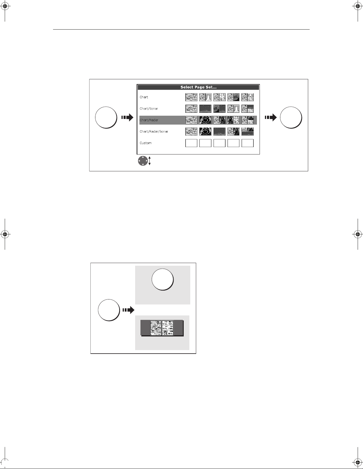
Selecting a page set
Your Display has four pre-configured page sets and one empty set for you to choose
from.
PAGE OK
Press &
hold
Highlight appropriate pre-configured page set
Note: Alternatively, you can access the Select Page Set screen via MENU.
If none of the pre-configured page sets meet your particular requirements and/or you
intend to use the engine monitor application, refer to the Setup and Customizing
chapter for details of how to customize both the layout and the application appearing
in each window.
D8511-1
Selecting an application page
Once you have selected the appropriate page set (see previous section), choose the
application page that you wish to use:
PAGE
Press until required
page displayed
PAGE
Or:
Press soft key of
required page
D8512-1
Chapter 2: General Operation 15
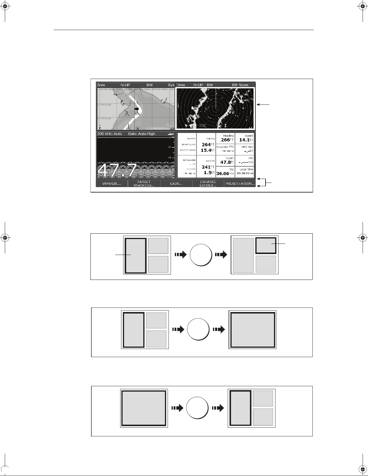
Selecting an application window
When the selected page has more than one window, the window that is currently
active will be bordered in red e.g.
Active window
highlighted
Soft keys
associated with
active window
D8516_1
Changing the active window
To change the active highlight to other windows on the page and display the
associated soft keys:
Active
window
e.g.
ACTIVE
Press to move
active window
Active
window
Multiple to single window
To make the active window full-screen when multiple windows are being displayed:
ACTIVE
Press and
Multiple windows Single window
hold
Single to multiple windows
To return to multiple windows:
D8513-1
D8514-1
ACTIVE
Multiple windowsSingle window
D8515_1
16 C-Series Display Reference Manual
Adjusting the display lighting
The display has two distinct color palettes, for day and night operation. You can also
manually adjust the backlight level.
Note: The display lighting is a local setting and will therefore only affect the individual
display on which you are working.
Day/night operation
To select the day/night mode of operation:
PALETTE
DAY NIGHT
Toggle as required
OK
The display saves the current palette when the unit is powered off. If the palette was set
to NIGHT when it was last used, and you then power on in bright sunlight, it may be
difficult to see the screen. Reset the palette to DAY to return to normal daytime
lighting.
Backlight level
To adjust the backlight level when in day or night operation mode:
Backlight Level
OK
Change the level as required
D6802-3
D8517_1
 Loading...