


 Loading...
ORDER NO.
CRT4545
AVIC-U220/XZUC
ADD-ON NAVIGATION SYSTEM
AVIC-U220/XZUC
HIDE-AWY NAVIGATION SYSTEM
AVIC-F220/XZEU5
AVIC-F220/XZUW5
AVIC-F220/XZAU
AVIC-F220/XZCS
For details, refer to "Important Check Points for Good Servicing".
PIONEER CORPORATION 1-1, Shin-ogura, Saiwai-ku, Kawasaki-shi, Kanagawa 212-0031, Japan PIONEER ELECTRONICS (USA) INC. P.O. Box 1760, Long Beach, CA 90801-1760, U.S.A.
PIONEER EUROPE NV Haven 1087, Keetberglaan 1, 9120 Melsele, Belgium
PIONEER ELECTRONICS ASIACENTRE PTE. LTD. 253 Alexandra Road, #04-01, Singapore 159936
 PIONEER CORPORATION 2010
K-ZZZ. APR. 2010 Printed in Japan

|
1 |
|
2 |
|
3 |
|
4 |
|
SAFETY INFORMATION
A
CAUTION
This service manual is intended for qualified service technicians; it is not meant for the casual do-it-yourselfer. Qualified technicians have the necessary test equipment and tools, and have been trained to properly and safely repair complex products such as those covered by this manual.
Improperly performed repairs can adversely affect the safety and reliability of the product and may void the warranty. If you are not qualified to perform the repair of this product properly and safely, you should not risk trying to do so and refer the repair to a qualified service technician.
WARNING
This product may contain a chemical known to the State of California to cause cancer, or birth defects or other reproductive harm.
B |
Health & Safety Code Section 25249.6 - Proposition 65 |
|
Where in a manufacturer’s service documentation, for example in circuit diagrams or lists
of components, a symbol is used to indicate that a specific component shall be replaced only by the component specified in that documentation for safety reasons, the following symbol shall be used:
C
D
E
F
2 |
AVIC-U220/XZUC |
|
1 |
|
2 |
|
3 |
|
4 |
|
|
|
|
|
|
|
5 |
|
6 |
|
7 |
|
8 |
|
[Important Check Points for Good Servicing]
In this manual, procedures that must be performed during repairs are marked with the below symbol. |
A |
|||||||
Please be sure to confirm and follow these procedures. |
|
|||||||
1. Product safety |
|
|||||||
|
|
|
|
|
|
|
Please conform to product regulations (such as safety and radiation regulations), and maintain a safe servicing environment by |
|
|
|
|
|
|
|
|
following the safety instructions described in this manual. |
|
|
|
|
|
|
|
|
1 Use specified parts for repair. |
|
|
|
|
|
|
|
|
|
|
|
||||||||
|
|
|
|
|
|
|
Use genuine parts. Be sure to use important parts for safety. |
|
|
|
|
|
|
|
|
2 Do not perform modifications without proper instructions. |
|
|
|
|
|
|
|
|
Please follow the specified safety methods when modification(addition/change of parts) is required due to interferences such as |
|
|
|
|
|
|
|
|
radio/TV interference and foreign noise. |
B |
|
|
|
|
|
|
|
3 Make sure the soldering of repaired locations is properly performed. |
|
|
|
|
|
|
|
|
When you solder while repairing, please be sure that there are no cold solder and other debris. |
|
|
|
|
|
|
|
|
Soldering should be finished with the proper quantity. (Refer to the example) |
|
|
|
|
|
|
|
|
4 Make sure the screws are tightly fastened. |
|
|
|
|
|
|
|
|
Please be sure that all screws are fastened, and that there are no loose screws. |
|
|
|
|
|
|
|
|
|
|
|
|
|
|
|
|
|
5 Make sure each connectors are correctly inserted. |
|
|
|
|
|
|
|
|
Please be sure that all connectors are inserted, and that there are no imperfect insertion. |
|
|
|
|
|
|
|
|
6 Make sure the wiring cables are set to their original state. |
C |
|
|
|
|
|
|
|
|
|
|
|
|
|
|
|
|
Please replace the wiring and cables to the original state after repairs. |
|
|
|
|
|
|
|
|
In addition, be sure that there are no pinched wires, etc. |
|
|
|
|
|
|
|
|
7 Make sure screws and soldering scraps do not remain inside the product. |
|
|
|
|
|
|
|
|
Please check that neither solder debris nor screws remain inside the product. |
|
|
|
|
|
|
|
|
8 There should be no semi-broken wires, scratches, melting, etc. on the coating of the power cord. |
|
|
|
|
|
|
|
|
|
|
|
||||||||
|
|
|
|
|
|
|
Damaged power cords may lead to fire accidents, so please be sure that there are no damages. |
|
|
|
|
|
|
|
|
If you find a damaged power cord, please exchange it with a suitable one. |
|
|
|
|
|
|
|
|
9 There should be no spark traces or similar marks on the power plug. |
|
|
|
|
|
|
|
|
When spark traces or similar marks are found on the power supply plug, please check the connection and advise on secure |
D |
|
|
|
|
|
|
|
connections and suitable usage. Please exchange the power cord if necessary. |
|
|
|
|
|
|
|
|
a Safe environment should be secured during servicing. |
|
|
|
|
|
|
|
|
When you perform repairs, please pay attention to static electricity, furniture, household articles, etc. in order to prevent injuries. |
|
|
|
|
|
|
|
|
Please pay attention to your surroundings and repair safely. |
|
2. Adjustments |
|
|||||||
|
||||||||
|
||||||||
|
|
|
|
|
|
|
To keep the original performance of the products, optimum adjustments and confirmation of characteristics within specification. |
|
|
|
|
|
|
||||
|
|
|
|
|
|
|
Adjustments should be performed in accordance with the procedures/instructions described in this manual. |
|
3. Lubricants, Glues, and Replacement parts |
|
|||||||
|
|
|
|
|
|
|
Use grease and adhesives that are equal to the specified substance. |
E |
|
|
|
|
|
|
|
|
|
|
|
|
|
|
|
|
Make sure the proper amount is applied. |
|
|
|
|
|
|
|
|
|
|
4. Cleaning |
|
|||||||
|
|
|
|
|
|
|
For parts that require cleaning, such as optical pickups, tape deck heads, lenses and mirrors used in projection monitors, proper |
|
|
|
|
|
|
|
|
cleaning should be performed to restore their performances. |
|
|
||||||||
|
|
|
|
|
|
|
|
|
5. Shipping mode and Shipping screws |
|
|||||||
|
|
|
|
|
|
|
To protect products from damages or failures during transit, the shipping mode should be set or the shipping screws should be |
|
|
|
|
|
|
|
|
installed before shipment. Please be sure to follow this method especially if it is specified in this manual. |
F |
|
|
|
|
|
|
|
||
|
|
|
|
|
|
|
|
|
|
|
|
|
AVIC-U220/XZUC |
|
|
|
3 |
|
||
|
5 |
|
6 |
|
|
7 |
|
8 |
|
|
|
|
|
|
|
|
|
||||||

|
1 |
|
|
2 |
|
3 |
|
4 |
|
|
CONTENTS |
|
|
|
|
|
|
||
|
SAFETY INFORMATION..................................................................................................................................... |
|
|
|
2 |
|
|||
|
1. SERVICE PRECAUTIONS ............................................................................................................................... |
|
|
|
5 |
|
|||
A |
1.1 SERVICE PRECAUTIONS ........................................................................................................................ |
|
|
|
5 |
|
|||
1.2 NOTES ON SOLDERING |
|
|
|
5 |
|
||||
|
|
|
|
|
|||||
|
2. SPECIFICATIONS............................................................................................................................................ |
|
|
|
6 |
|
|||
|
2.1 SPECIFICATIONS ..................................................................................................................................... |
|
|
|
6 |
|
|||
|
2.2 DISC/CONTENT FORMAT ........................................................................................................................ |
|
|
|
7 |
|
|||
|
2.3 PANEL FACILITIES.................................................................................................................................... |
|
|
|
7 |
|
|||
|
2.4 CONNECTION DIAGRAM |
|
|
|
8 |
|
|||
|
|
|
|
|
|||||
|
........................................................................................................................3. BASIC ITEMS FOR SERVICE |
|
|
|
10 |
|
|||
|
3.1 CHECK POINTS AFTER SERVICING..................................................................................................... |
|
|
10 |
|
||||
|
4. BLOCK DIAGRAM.......................................................................................................................................... |
|
|
|
12 |
|
|||
|
4.1 BLOCK DIAGRAM ................................................................................................................................... |
|
|
|
12 |
|
|||
|
5. DIAGNOSIS.................................................................................................................................................... |
|
|
|
14 |
|
|||
B |
5.1 DIAGNOSIS FLOWCHART ..................................................................................................................... |
|
|
|
14 |
|
|||
|
5.2 CONNECTOR FUNCTION DESCRIPTION............................................................................................. |
|
|
17 |
|
||||
|
6. SERVICE MODE ............................................................................................................................................ |
|
|
|
19 |
|
|||
|
6.1 TEST MODE ............................................................................................................................................ |
|
|
|
19 |
|
|||
|
7. DISASSEMBLY .............................................................................................................................................. |
|
|
|
25 |
|
|||
|
8. EACH SETTING AND ADJUSTMENT ........................................................................................................... |
|
|
|
27 |
|
|||
|
9. EXPLODED VIEWS AND PARTS LIST |
|
|
|
28 |
|
|||
|
|
|
|
|
|||||
|
|
|
|
|
|||||
|
9.1 PACKING ................................................................................................................................................. |
|
|
|
28 |
|
|||
|
9.2 EXTERIOR............................................................................................................................................... |
|
|
|
32 |
|
|||
C
D
E
F
4 |
AVIC-U220/XZUC |
|
1 |
|
2 |
|
3 |
|
4 |
|
|
|
|
|
|

|
5 |
|
6 |
|
7 |
|
8 |
|
1. SERVICE PRECAUTIONS
1.1 SERVICE PRECAUTIONS
A
1.You should conform to the regulations governing the product (safety, radio and noise, and other regulations), and should keep the safety during servicing by following the safety instructions described in this manual.
2.Be careful in handling ICs. Some ICs such as MOS type are so fragile that they can be damaged by electrostatic
induction.
3.Before disassembling the unit, be sure to turn off the power. Unplugging and plugging the connectors during power-on mode may damage the ICs inside the unit.
4.This model must be required to connect AVH series 2010 year or later for operation check.
1.2 NOTES ON SOLDERING
 For environmental protection, lead-free solder is used on the printed circuit boards mounted in this unit.
Be sure to use lead-free solder and a soldering iron that can meet specifications for use with lead-free solders for repairs accompanied by reworking of soldering.
 Compared with conventional eutectic solders, lead-free solders have higher melting points, by approximately 40
  C. Therefore, for lead-free soldering, the tip temperature of a soldering iron must be set to around 373
  C in general, although the temperature depends on the heat capacity of the PC board on which reworking is required and the weight of the tip of the soldering iron.
Compared with eutectic solders, lead-free solders have higher bond strengths but slower wetting times and higher melting temperatures (hard to melt/easy to harden).
The following lead-free solders are available as service parts:
 Parts numbers of lead-free solder:
GYP1006 1.0 in dia.
GYP1007 0.6 in dia.
GYP1008 0.3 in dia.
B
C
D
E
F
|
|
|
|
AVIC-U220/XZUC |
|
|
|
5 |
|
||
|
5 |
|
6 |
|
|
7 |
|
8 |
|
|
|
|
|
|
|
|
|
||||||

|
1 |
|
2 |
|
3 |
|
4 |
|
2. SPECIFICATIONS
2.1 SPECIFICATIONS
A |
AVIC-U220 |
|
||
|
|
|
||
|
|
General |
|
|
|
|
Rated power source............... |
14.4 V DC |
|
|
|
|
(allowable voltage range: |
|
|
|
|
10.8 V to 15.1 V DC) |
|
|
|
Grounding system |
Negative type |
|
|
|
|||
|
|
Maximum current consumption |
||
|
|
..................................................... |
1.0 A |
|
|
|
Backup current .......................... |
0.2 mA or less |
|
|
|
Dimensions (W × H × D): |
|
|
B |
............................................... |
85 mm × 28 mm × 147 mm |
||
|
(3-3/8 in. × 1-1/8 in. × |
|||
|
|
|
||
|
|
|
5-3/4 in.) |
|
|
|
Detachable device ........ |
70 mm ×17 mm ×99 mm |
|
|
|
|
(2-3/4 in. × 5/8 in. × |
|
|
|
|
3-7/8 in.) |
|
|
|
Weight .......................................... |
195 g (0.43 lbs) |
|
|
|
|||
|
|
.............NAND flash memory |
2 GB |
|
|
|
Navigation |
|
|
|
|
GPS receiver: |
|
|
|
|
System ................................ |
L1, C/Acode GPS |
|
C |
|
SPS (Standard Positioning |
||
|
Service) |
|||
|
|
|
||
|
|
Reception system.......... |
20-channel multi-channel |
|
|
|
|
reception system |
|
|
|
Reception frequency.... |
1 575.42 MHz |
|
|
|
Sensitivity .......................... |
– 140 dBm (typ) |
|
|
|
Position update frequency |
||
|
|
|||
|
|
GPS antenna: |
Approx. once per second |
|
|
|
|||
|
|
|
||
|
|
Antenna ............................. |
Micro strip flat antenna/ |
|
|
|
|
right-handed helical polari- |
|
|
|
|
zation |
|
D |
Antenna cable ................. |
3.55 m (11 ft. 10 in.) |
||
Dimensions (W × H × D) |
||||
|
|
|||
|
|
........................................... |
33 mm × 14.7 mm × 36 mm |
|
|
|
|
(1-1/4 in. × 4/7 in. × |
|
|
|
|
1-3/8 in.) |
|
|
|
Weight ................................ |
96 g (0.21 lbs) |
|
|
|
USB |
|
|
|
|
|
||
|
|
|
||
|
|
USB standard spec................ |
USB 2.0 High Speed |
|
|
|
Max current supply ................. |
500 mA |
|
|
|
File system.................................. |
FAT16, FAT32 |
|
|
|
USB class.................................... |
Mass storage class |
|
E |
SD |
|
||
|
|
Compatible physical format |
|
|
|
|
..................................................... |
Version 2.00 |
|
|
|
Max memory capacity........... |
16 GB |
|
|
|
File system.................................. |
FAT16, FAT32 |
|
 Note
Note
Specifications and design are subject to possible modifications without notice due to improvements.
F
AVIC-F220
General
Rated power source............... |
14.4 V DC |
|
(allowable voltage range: |
|
10.8 V to 15.1 V DC) |
Earthing system ....................... |
Negative type |
Maximum current consumption |
|
..................................................... |
1.0 A |
Backup current .......................... |
0.2 mA or less |
Dimensions (W × H × D): |
|
............................................... |
85 mm × 28 mm × 147 mm |
Detachable device ........ |
70 mm ×17 mm ×99 mm |
Weight .......................................... |
196 g(EU5 ,AU) |
.......................................... |
195 g(UW5, CS) |
NAND flash memory ............. |
2 GB (AU, UW5, CS) |
|
4 GB (EU5) |
Navigation
GPS receiver: |
|
System ................................ |
L1, C/Acode GPS |
|
SPS (Standard Positioning |
|
Service) |
Reception system.......... |
20-channel multi-channel |
|
reception system |
Reception frequency.... |
1 575.42 MHz |
Sensitivity .......................... |
–140 dBm (typ) |
Position update frequency |
|
........................................... |
Approx. once per second |
GPS aerial: |
|
Aerial ................................... |
Micro strip flat aerial/right- |
|
handed helical polarisation |
Aerial cable ...................... |
3.55 m |
Dimensions (W × H × D) |
|
........................................... |
33 mm × 14.7 mm × 36 mm |
Weight ................................ |
96 g |
USB
USB standard spec................ |
USB 2.0 High Speed |
Max current supply ................. |
500 mA |
File system.................................. |
FAT16, FAT32 |
USB class.................................... |
Mass storage class |
SD
Compatible physical format |
|
..................................................... |
Version 2.00 |
Max memory capacity........... |
16 GB |
File system.................................. |
FAT16, FAT32 |
RDS-TMC tuner(EU5, AU)
Earthing system ....................... |
Negative type |
Maximum current consumption |
|
..................................................... |
60 mA |
Dimensions (W × H × D) ... |
68 mm × 49 mm × 19 mm |
Weight .......................................... |
180 g |
 Note
Note
Specifications and design are subject to possible modifications without notice due to improvements.
6 |
AVIC-U220/XZUC |
|
1 |
|
2 |
|
3 |
|
4 |
|
|
|
|
|
|
|
5 |
|
6 |
|
7 |
|
8 |
|
2.2 DISC/CONTENT FORMAT
A
B
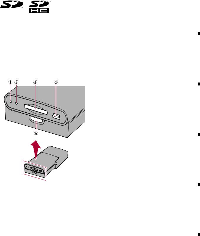
2.3 PANEL FACILITIES
1 Power indicator
2 RESET button
3 SD card slot
C
4 USB port (Mini-B)
Use to connect with your PC.
5 Detach button
Press to remove the detachable device from the base unit. 
D
E
F
|
|
|
|
AVIC-U220/XZUC |
|
|
|
7 |
|
||
|
5 |
|
6 |
|
|
7 |
|
8 |
|
|
|
|
|
|
|
|
|
||||||
|
|
1 |
|
|
2 |
|
|
3 |
|
4 |
|
|
|
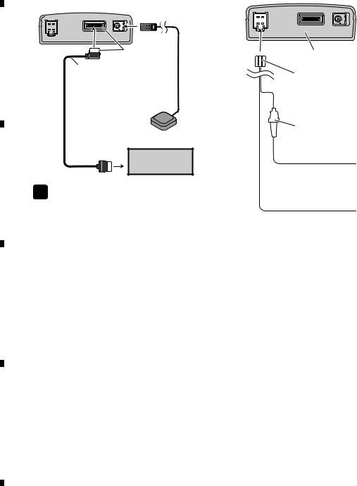
2.4 CONNECTION DIAGRAM |
|
|
|
|
|
|
|||
A - UC, EW5, CS |
|
|
|
|
|
|
|
||||
|
|
Connecting the system |
|
Connecting the power cord |
|
|
|
||||
Base unit
 Green
Green
|
|
Yellow |
B |
26-pin cable |
|
|
3.55 m |
|
|
(supplied) |
|
|
(11 ft. 8 in.) |
|
|
|
2 m (6 ft. 7 in.)
GPS antenna
AV receiver
C
 Note
Note
The terminal form of the 26-pin cable may differ depending on the terminal type of the AV receiver. For details of connection, refer to the installation manual supplied with the AV receiver.
D
E
F
Base unit
Power cord
Fuse holder
Yellow
To terminal always supplied with power regardless of ignition switch position.
Black (ground)
To vehicle (metal) body.
8 |
AVIC-U220/XZUC |
|
1 |
|
2 |
|
3 |
|
4 |
|
|
|
|
|
|

|
Connecting the system |
Connecting the power cord |
5
U220/XZUC-AVIC 7 6
We recommend connecting the supplied external aerial. Connect the aerial plug of your vehicle to the AV receiver directly (Fig. 1).
If you do not use the supplied external aerial in order to split radio signal between this product and the built-in tuner of the AV receiver (Fig. 2), the radio sensitivity of the AV receiver may decrease.
|
|
Green |
Base unit |
|
3.55 m |
|
GPS aerial |
|
|
|
|
|
Yellow |
Vehicle aerial |
Expansion port |
Aerial jack of AV receiver |
26-pin cable (supplied)
1 m |
2 m |
AV receiver |
|
||
|
|
|
|
30 cm |
RGB input |
30 cm |
|
|
|
|
Not used.
Aerial jack
External aerial(supplied)
RDS-TMC tuner (supplied)
For more details about the wiring.
(Fig. 1)
Aerial jack
Vehicle aerial
Aerial plug
Aerial jack of AV receiver
AV receiver
RDS-TMC tuner
Base unit
Power cord
Fuse holder
Yellow
To terminal always supplied with power regardless of ignition switch position.
Black (earth)
To vehicle (metal) body.
(Fig. 2)
 Note
Note
The terminal form of the 26-pin cable may differ
8 |
depending on the terminal type of the AV receiver. |
|
|
|
For details of connection, refer to the installation |
|
manual supplied with the AV receiver. |
9 |
|
|
|
|
|
|
|
|
|
|
|
F |
|
E |
|
D |
|
C |
|
B |
|
|
|
|
|
|
|
|||||
AU EU5, - |
|
|
5 |
||
|
|
|
|
|
|
6
7
8
A

|
1 |
|
2 |
|
3 |
|
4 |
|
3. BASIC ITEMS FOR SERVICE
3.1 CHECK POINTS AFTER SERVICING
A
To keep the product quality after servicing, please confirm following check points.
|
|
No. |
|
Procedures |
Item to be confirmed |
|
|
1 |
|
Confirm whether the customer complain has |
The customer complain must not be reappeared. |
|
|
|
|
been solved. |
Display, video, audio and operations must be |
|
|
|
|
If the customer complain occurs with the |
normal. |
|
|
|
|
||
|
|
|
|
|
|
|
|
|
|
specific media, use it for the operation check. |
|
|
|
|
|
|
|
|
|
2 |
GPS positioning |
Connect GPS antenna to the product, and |
Current location must be correct. |
|
|
|
|
check whether the current location is correct. |
Display and operations must be normal. |
B |
|
|
|
|
|
3 |
Map display |
Check functions of map scale change and map |
Display and operations must be normal. |
||
|
|
|
Touch-panel |
scroll. |
|
|
|
|
operation |
|
|
|
|
|
Remote-control |
|
|
|
|
|
operation |
|
|
|
|
|
|
|
|
|
|
4 |
|
Delete data added during the operating check. |
Make sure to delete data added during the |
|
|
|
|||
|
|
|
|||
|
|
|
|
Check whether no media (CD etc.) is inside the |
operating check. |
|
|
|
|
product. |
The media used for the operating check must |
|
|
|
|
|
be ejected. |
|
|
|
|
|
|
|
|
5 |
|
Appearance check |
No scratches or dirt on its appearance after |
C |
|
|
|
receiving it for service. |
|
See the table below for the items to be checked regarding video and audio:
|
|
Item to be checked regarding video |
Item to be checked regarding audio |
|
|
|
|
|
|
Block-noise |
Distortion |
|
|
Horizontal noise |
Noise |
|
|||
|
|
Dot noise |
Volume too low |
|
|
Disturbed image (video jumpiness) |
Volume too high |
|
|
Too dark |
Volume fluctuating |
|
|
Too bright |
Sound interrupted |
|
|
Mottled color |
|
D |
|
|
|
|
|
|
|
|
|
|
|
E
F
10 |
AVIC-U220/XZUC |
|
1 |
|
2 |
|
3 |
|
4 |
|
|
|
|
|
|
Loading...