


Installation Manual
Manuel d’installation
NAVIGATION AV SYSTEM
SYSTEME DE NAVIGATION AV
SISTEMA DI NAVIGAZIONE AV
SISTEMA DE NAVEGACIÓN AV
NAVIGATIONS-/AV-SYSTEM
AV NAVIGATIESYSTEEM
AVIC-F860BT
Nederlands Deutsch Español Italiano Français English


 Contents
Precautions |
|
|
|
Your new product and this manual |
3 |
||
Important safeguards |
3 |
|
|
Connection |
|
|
|
Precautions before connecting the |
|
||
system 5 |
|
|
|
Before installing this product |
5 |
|
|
To prevent damage 6 |
|
|
|
– Notice for the blue/white lead |
6 |
||
Parts supplied 7 |
|
|
|
Connecting the power cord (1) |
8 |
|
|
Connecting the power cord (2) |
10 |
|
|
Connecting the system |
12 |
|
|
Connecting to separately sold power |
|
||
amp 13 |
|
|
|
|
|
|
Connecting an iPhone with Lightning |
|
|||||
connector |
14 |
|
|
|
|
|
– |
Connecting via the USB port 14 |
|||||
Connecting an iPhone with 30-pin |
|
|||||
connector |
14 |
|
|
|
|
|
– |
Connecting via the AUX input |
14 |
||||
– |
Connecting via the RGB input |
15 |
||||
Connecting the MirrorLink™ device |
15 |
|||||
Connecting a rear view camera |
16 |
|
||||
Connecting the external video |
|
|
||||
component |
17 |
|
|
|
|
|
– |
Using AV input |
17 |
|
|
|
|
– |
Using an AUX input |
18 |
|
|
||
Connecting the rear display |
19 |
|
|
|||
– |
When using a rear display connected to |
|||||
|
rear video output |
19 |
|
|
|
|
Installation |
|
|
|
|
|
|
Precautions before installation |
20 |
|
||||
To avoid electromagnetic interference |
20 |
|||||
Before installing 20 |
|
|
|
|
||
Installing this product |
21 |
|
|
|
||
– |
Installation notes |
21 |
|
|
|
|
– |
Parts supplied 21 |
|
|
|
||
– |
Installation using the screw holes on |
|||
|
the side of this product |
22 |
||
Installing the GPS aerial |
23 |
|
||
– |
Installation notes 23 |
|
||
– |
Parts supplied |
23 |
|
|
– |
When installing the aerial inside the |
|||
|
vehicle (on the dashboard or rear |
|||
|
shelf) 24 |
|
|
|
Installing the microphone |
25 |
|||
– |
Parts supplied |
25 |
|
|
– |
Mounting on the sun visor 25 |
|||
– |
Installation on the steering column 26 |
|||
– |
Adjusting the microphone angle 26 |
|||
After installation |
|
|
|
|
After installing this product |
27 |
|||
 2
2 Engb
Engb

 Precautions
Your new product and this |
Important safeguards |
|
manual |
WARNING |
|
! The navigation features of this product |
||
Pioneer does not recommend that you install |
||
(and the rear view camera option if pur- |
this product yourself. This product is de- |
|
chased) are intended solely to aid you in |
signed for professional installation only. We |
|
the operation of your vehicle. It is not a sub- |
recommend that only authorised Pioneer ser- |
|
stitute for your attentiveness, judgement |
vice personnel, who have special training |
|
and care when driving. |
and experience in mobile electronics, set up |
|
! Never use this product to route to hospi- |
and install this product. NEVER SERVICE |
|
tals, police stations, or similar facilities in |
THIS PRODUCT YOURSELF. Installing or |
|
an emergency. Please call the appropriate |
servicing this product and its connecting |
|
emergency number. |
cables may expose you to the risk of electric |
|
! Do not operate this product, any applica- |
shock or other hazards, and can cause da- |
|
tions, or the rear view camera option (if pur- |
mage to this product that is not covered by |
|
chased) if doing so will divert your attention |
warranty. |
|
in any way from the safe operation of your |
|
|
vehicle. Always observe safe driving rules |
! Read this manual fully and carefully before |
|
and follow all existing traffic regulations. If |
installing this product. |
|
you experience difficulty in operating this |
! Keep this manual handy for future refer- |
|
product or reading the display, park your |
ence. |
|
vehicle in a safe location and apply the |
! Pay close attention to all warnings in this |
|
handbrake before making the necessary |
manual and follow the instructions care- |
|
adjustments. |
fully. |
|
! This manual explains how to install this |
! This product may in certain circumstances |
|
product in your vehicle. Operation of this |
display inaccurate position of your vehicle, |
|
product is explained in the separate man- |
the distance of objects shown on the |
|
uals. |
screen, and compass directions. In addi- |
|
! Do not install this product where it may (i) |
tion, the system has certain limitations, in- |
|
obstruct the driver’s vision, (ii) impair the |
cluding the inability to identify one-way |
|
performance of any of the vehicle’s operat- |
streets, temporary traffic restrictions and |
|
ing systems of safety features, including |
potentially unsafe driving areas. Please ex- |
|
airbags, hazard lamp buttons, or (iii) impair |
ercise your own judgement in the light of |
|
the driver’s ability to safely operate the vehi- |
actual driving conditions. |
|
cle. In some cases, it may not be possible |
! As with any accessory in your vehicle’s in- |
|
to install this product because of the vehi- |
terior, this product should not divert your |
|
cle type or the shape of the vehicle inter- |
attention from the safe operation of your |
|
ior. |
vehicle as it may result in serious injury or |
|
|
death. If you experience difficulty in operat- |
|
|
ing the system or reading the display, |
|
|
please make adjustments while safely |
|
|
parked. |
|
|
! Please remember to wear your seat belt at |
|
|
all times while operating your vehicle. If |
|
|
you are in an accident, your injuries can be |
|
|
considerably more severe if your seat belt |
|
|
is not properly fastened. |
Section
01
English
Engb  3
3

Section
01  Precautions
!Certain country and government laws may prohibit or restrict the placement and use of this product in your vehicle. Please comply with all applicable laws and regulations
regarding the use, installation and operation of this product.
 4
4 Engb
Engb

 Connection
Precautions before |
damaged, resulting in a short circuit or |
|
connecting the system |
malfunction and permanent damage to |
|
the product. |
||
|
||
WARNING |
! Do not cut the GPS aerial cable to shorten |
|
it or use an extension to make it longer. |
||
Do not take any steps to tamper with or dis- |
||
Altering the aerial cable could result in a |
||
able the handbrake interlock system which |
||
short circuit or malfunction. |
||
is in place for your protection. Tampering |
||
! Do not shorten any leads. If you do, the |
||
with or disabling the handbrake interlock |
||
protection circuit (fuse holder, fuse resis- |
||
system could result in serious injury or |
||
tor or filter, etc.) may fail to work properly. |
||
death. |
||
! Never feed power to other electronic pro- |
||
|
||
CAUTION |
ducts by cutting the insulation of the |
|
power supply lead of this product and tap- |
||
! If you decide to perform the installation |
ping into the lead. The current capacity of |
|
yourself, and have special training and ex- |
the lead will be exceeded, causing over- |
|
perience in the mobile electronics instal- |
heating. |
|
lations, please carefully follow all of the |
|
|
steps in the installation manual. |
|
|
! Secure all wiring with cable clamps or |
Before installing this product |
|
electrical tape. Do not allow any bare wir- |
||
! Use this unit with a 12-volt battery and ne- |
||
ing to remain exposed. |
||
! Do not directly connect the yellow lead of |
gative earthing only. Failure to do so may |
|
this product to the vehicle battery. If the |
result in a fire or malfunction. |
|
lead is directly connected to the battery, |
! To avoid shorts in the electrical system, be |
|
engine vibration may eventually cause |
sure to disconnect the (–) battery cable be- |
|
the insulation to fail at the point where |
fore installation. |
|
the wire passes from the passenger com- |
|
|
partment into the engine compartment. If |
|
|
the yellow lead’s insulation tears as a re- |
|
|
sult of contact with metal parts, short-cir- |
|
|
cuiting can occur, resulting in |
|
|
considerable danger. |
|
!It is extremely dangerous to allow cables to become wound around the steering column or gearstick. Be sure to install this product, its cables, and wiring away in such so that they will not obstruct or hinder driving.
!Make sure that the cables and wires will not interfere with or become caught in any of the vehicle’s moving parts, especially the steering wheel, gearstick, handbrake, sliding seat tracks, doors, or any of the vehicle’s controls.
!Do not route wires where they will be exposed to high temperatures. If the insulation heats up, wires may become
Section
02
English
Engb  5
5
Section |
|
|
|
|
02 |
|
Connection |
|
|
|
|
|
|
|
|
To prevent damage |
! Since a unique BPTL circuit is employed, |
||
|
|
|
do not directly earth the * side of the |
|
|
|
WARNING |
speaker lead or connect the * side of an- |
|
|
! Use speakers over 50 W (output value) |
other side of the speaker lead together. Be |
||
|
|
and between 4 W to 8 W (impedance value). |
sure to connect the * side of the speaker |
|
|
|
Do not use 1 W to 3 W speakers for this |
lead to the * side of the speaker lead on |
|
|
|
unit. |
this product. |
|
|
! The black lead is earth. Please earth this |
|
|
|
|
|
lead separately from the earth of high-cur- |
Notice for the blue/white lead |
|
|
|
rent products such as power amps. Do not |
||
|
|
! When the ignition switch is turned on (ACC |
||
|
|
earth more than one product together |
||
|
|
with the earth from another product. For |
ON), a control signal is output through the |
|
|
|
example, you must separately earth any |
blue/white lead. Connect to an external |
|
|
|
amp unit away from the earth of this pro- |
power amp’s system remote control term- |
|
|
|
duct. Connecting earths together can |
inal, the auto-aerial relay control terminal, |
|
|
|
cause a fire and/or damage the products if |
or the aerial booster power control terminal |
|
|
|
their earths became detached. |
(max. 300 mA 12 V DC). The control signal |
|
|
! When replacing the fuse, be sure to only |
is output through the blue/white lead, even |
||
|
|
use a fuse of the rating prescribed on this |
if the audio source is switched off. |
|
|
|
product. |
! Be sure not to use this lead as the power |
|
|
|
! When disconnecting a connector, pull the |
supply lead for the external power amps. |
|
|
|
connector itself. Do not pull the lead, as |
Such connection could cause excessive |
|
|
|
you may pull it out of the connector. |
current drain and malfunction. |
|
|
|
! This product cannot be installed in a vehi- |
! Be sure not to use this lead as the power |
|
|
|
cle without ACC (accessory) position on |
supply lead for the auto-aerial or aerial |
|
|
|
the ignition switch. |
booster. Such connection could cause ex- |
|
|
|
|
cessive current drain and malfunction. |
|
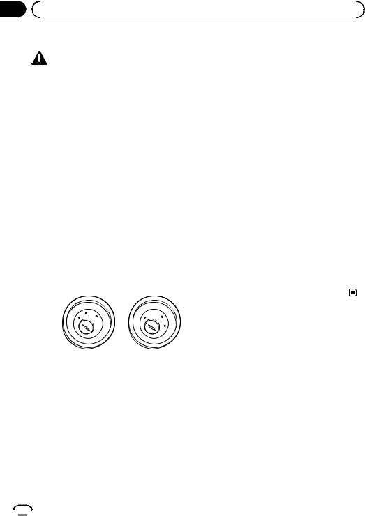
O
FF
ACC
O
N
S  TA
TA
T
O
FF
O
N
S
TA
T
ACC position |
No ACC position |
!To avoid short-circuiting, cover the disconnected lead with insulating tape. It is especially important to insulate all unused speaker leads, which if left uncovered may cause a short circuit.
!Attach the connectors of the same colour to the corresponding coloured port, i.e., blue connector to the blue port, black to black, etc.
!Refer to the owner’s manual for details on connecting the power amp and other units, then make connections accordingly.
 6
6 Engb
Engb
 Connection
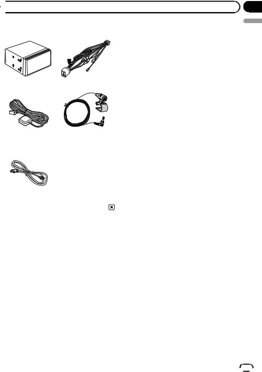
Parts supplied
This product |
Power cord |
GPS aerial |
Microphone |
USB cable
Section
02
English
Engb  7
7

Section
02  Connection
Connecting the power cord (1)
 Note
Note
Depending on the types of vehicles, the function of *2 and *4 may be different. In this case, be sure to connect *1 to *4 and *3 to *2 as shown in the figure.
*2 *1
*4 *3
 Notes
Notes
·When a subwoofer (*5) is connected to this product instead of a rear speaker, change the rear output setting in the initial setting. (Refer to Operation Manual.) The subwoofer output of this product is monaural.
·When using a subwoofer of 70 W (2 Ω), be sure to connect with violet and violet/black leads of this product. Do not connect anything with green and green/black leads.
Connect leads of the same colour to each other.
Yellow (*2) |
Yellow (*1) |
Back-up |
To terminal supplied with |
(or accessory) |
power regardless of ignition |
|
switch position. |
Red (*4) |
Red (*3) |
Accessory |
To electric terminal controlled by |
(or back-up) |
ignition switch (12 V DC) ON/OFF. |
|
Orange/white |
|
To lighting switch terminal. |
|
Black (earth) |
|
To vehicle (metal) body. |
|
|
|
|
|
|
|
|
|
|
ISO connector |
|
|
||
|
|
|
Speaker leads |
|
|
|
|
White: |
Front left |
|
|
|
White/black: |
Front left |
|
|
Note |
Grey: |
Front right |
|
|
Grey/black: |
Front right |
|
|
In some vehicles, the ISO connector may be divided |
Green: |
Rear left or Subwoofer (*5) |
|
|
Green/black: Rear left or Subwoofer (*5) |
|||
|
into two. In this case, be sure to connect to both |
|||
|
Violet: |
Rear right or Subwoofer (*5) |
||
|
connectors. |
|||
|
Violet/black: |
Rear right or Subwoofer (*5) |
||
|
|
|
||
 8
8 Engb
Engb

 Connection
This product
Fuse (10 A)
Power cord
14 cm
|
Yellow/black (MUTE) |
|
If you use equipment with a mute function, connect |
|
that equipment to the Audio Mute lead. If not, keep |
Power supply |
the Audio Mute lead free of any connections. |
|
 Note
Note
Audio source will be set to mute or attenuate, while the following sounds will not be muted or attenuated. For details, refer to Operation Manual.
—Voice guidance of the navigation
—Incoming ringtone and incoming voice of the mobile phone that is connected to this product via Bluetooth wireless technology
Section
02
English
Blue/white (*6)
The pin position of the ISO connector will differ depending on the types of vehicles. Connect *6 and *7 when Pin 5 is an aerial control type. In other types of vehicles, never connect *6 and *7.
Blue/white (*7)
To auto-aerial relay control terminal or aerial booster power control terminal (max. 300 mA 12 V DC).
Engb  9
9

Section
02  Connection
Connecting the power cord (2)
Pink (CAR SPEED SIGNAL INPUT)
This product is connected here to detect the distance the vehicle travels. Always connect the vehicle’s speed detection circuit. Failure to make this connection will increase errors in the vehicle’s location display.
 WARNING
IMPROPER CONNECTION MAY RESULT IN SERIOUS DAMAGE OR INJURY INCLUDING ELECTRICAL SHOCK, AND INTERFERENCE WITH THE OPERATION OF THE VEHICLE´S ANTILOCK BRAKING SYSTEM, AUTOMATIC GEARBOX AND SPEEDOMETER INDICATION.
 CAUTION
It is strongly suggested that the speed pulse wire be connected for accuracy of navigation and better performance.
 Note
Note
The position of the speed detection circuit and the position of the handbrake switch vary depending on the vehicle model. For details, consult your authorised Pioneer dealer or an installation professional.
Light green (PARKING BRAKE)
Used to detect the ON/OFF status of the handbrake. This lead must be connected to the power supply side of the handbrake switch.
If this connection is made incorrectly or omitted, certain functions of this product will be unusable.
 WARNING
LIGHT GREEN LEAD AT POWER CONNECTOR IS
DESIGNED TO DETECT PARKED STATUS AND MUST
BE CONNECTED TO THE POWER SUPPLY SIDE OF THE
HANDBRAKE SWITCH. IMPROPER CONNECTION OR
USE OF THIS LEAD MAY VIOLATE APPLICABLE LAW
AND MAY RESULT IN SERIOUS INJURY OR DAMAGE.
Connection method |
|
Clamp the lead of the power supply |
Power supply side |
side of the handbrake switch. |
|
Clamp firmly with needle-nosed |
Earth side |
|
|
pliers. |
Handbrake switch |
|
 10
10 Engb
Engb
|
Section |
Connection |
02 |
|
English |
This product
Power cord |
Power supply |
Violet/white (REVERSE-GEAR SIGNAL INPUT)
This is connected so that this product can detect whether the vehicle is moving forwards or backwards. Connect the violet/white lead to the lead whose voltage changes when the reverse gear is engaged. Unless connected, the sensor may not detect your vehicle travelling forward/backward properly, and thus the position of your vehicle detected by the sensor may be misaligned from the actual position.
 Note
Note
When you use a rear view camera, please make sure to connect this lead. Otherwise you cannot switch to the rear view camera picture.
Engb  11
11
Section
02  Connection
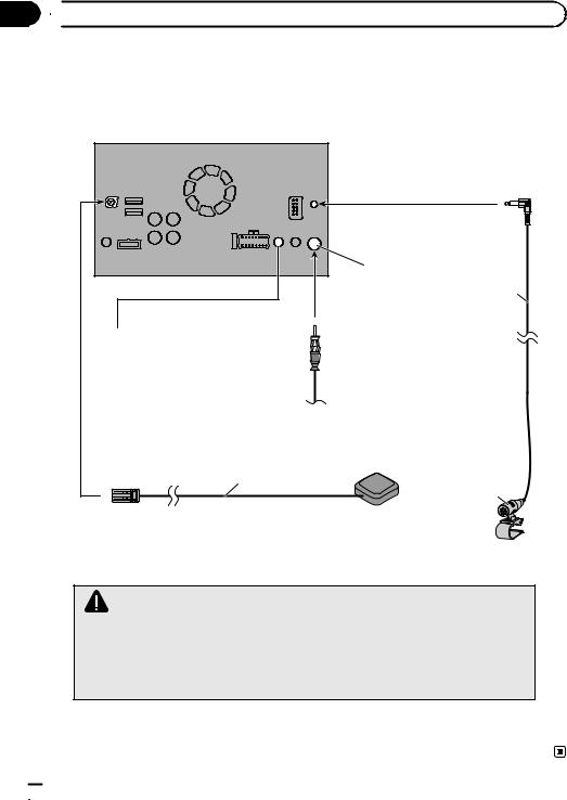
Connecting the system
This product
Aerial jack |
4 m
Wired remote input
Please refer to the instruction manual for the Hard-wired remote control adapter (sold separately).
Vehicle aerial
GPS aerial
3.55 m
Microphone
WARNING
·To avoid the risk of accident and the potential violation of applicable laws, this product should never be used while the vehicle is being driven except for navigation purposes. And, also rear displays should not be in a location where it is a visible distraction to the driver.
·In some countries, the viewing of images on a display inside a vehicle even by persons other than the driver may be illegal. Where such regulations apply they must be obeyed and this product’s video source should not be used.
 12
12 Engb
Engb

 Connection
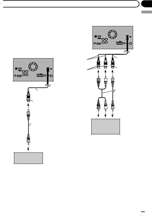
Connecting to separately sold power amp
|
Power amp |
|
|
(sold separately) |
|
Rear outputs |
RCA cables |
|
(sold separately) |
||
(REAR OUTPUT) |
||
|
||
|
Power amp |
|
|
(sold separately) |
15 cm
Power amp (sold separately)
Front outputs (FRONT OUTPUT)
This product
White, Red (SWL, SWR) |
Power supply |
 Power cord
 Blue/white
To system control terminal of the power amp (max. 300 mA 12 V DC).
If your vehicle is equipped with an auto-aerial, connect this lead to a power amp.
System remote control
|
|
|
|
|
|
|
|
|
|
|
|
Front speaker |
|
|
Rear speaker |
|
Subwoofer |
 Notes
Notes
·You can change the RCA output of the subwoofer depending on your subwoofer system. (Refer to Operation Manual.)
·The subwoofer output of this product is monaural.
Section
02
English
Engb  13
13

Section
02  Connection
Connecting an iPhone with |
Connecting an iPhone with |
Lightning connector |
30-pin connector |
 Notes
Notes
!For details on how to connect an external device using a separately sold cable, refer to the manual for the cable.
!For details concerning the connection, operations and compatibility of iPhone, refer to Operation Manual.
 Notes
Notes
!For details on how to connect an external device using a separately sold cable, refer to the manual for the cable.
!For details concerning the connection, operations and compatibility of iPhone, refer to Operation Manual.
Connecting via the USB port |
Connecting via the AUX input |
The USB interface cable for iPod / iPhone (CD- |
The USB interface cable for iPod / iPhone (CD- |
IU52) (sold separately) is required for the con- |
IU201V) (sold separately) is required for the |
nection. |
|
connection. |
|
|
USB port 1 |
USB port 1 |
This product |
|
This product |
|
|
|
|
|
|
|
|
USB port 2 |
AUX input |
|
USB port 2 |
|
|
|
|
USB cable |
iPhone with |
|
|
30-pin connector |
|
|
|
1.5 m |
|
iPhone with  Lightning connector
USB interface cable for iPod / iPhone
(CD-IU201V) (sold separately)
USB cable 1.5 m
 Note
Note
Connect the USB cable to USB port 1 when using “aha” as the source.
USB interface cable for iPod / iPhone (CD-IU52) (sold separately)
 14
14 Engb
Engb

 Connection
Connecting via the RGB input |
Connecting the MirrorLink™ |
The USB interface cable for iPod / iPhone (CD- |
device |
IU201S) (sold separately) is required for the
connection. |
|
USB port 1 |
This product |
RGB input
iPhone with 30-pin connector 
The USB interface cable for use with MirrorLink™ devices (CD-MU200) (sold separately) is required for the connection.
This product
USB port 2
MirrorLink device
USB cable
(supplied with CD-MU200)
Section
02
English
USB cable 1.5 m
USB interface cable for iPod / iPhone (CD-IU201S) (sold separately)
USB - micro USB cable (Type USB A - micro USB B) (supplied with CD-MU200)
 Note
Note
For details on how to connect an external device using a separately sold cable, refer to the manual for the cable.
Engb  15
15

Section |
|
|
|
|
|
|
|
02 |
|
Connection |
|
|
|
|
|
|
|
|
|
|
|
|
|
|
Connecting a rear view camera |
|
|
|
|
|
|
|
Rear view camera |
|
|||||
|
When this product is used with a rear view |
(ND-BC6) |
|
||||
|
camera, it is possible to automatically switch |
(sold separately) |
|
||||
|
|
|
|
|
|
||
|
from the video to rear view image when the |
|
|
|
|
|
|
|
|
|
|
|
|
||
|
gearstick is moved to REVERSE (R). Camera |
|
|
|
To video output |
||
|
|
|
|
||||
|
View mode also allows you to check what is |
|
|
|
|||
|
behind you while driving. |
|
|
|
RCA cable |
||
|
|
|
|
|
|
||
|
|
WARNING |
|
|
|
(supplied with ND-BC6) |
|
|
|
|
|
|
|
|
|
|
|
|
|
|
|
||
|
|
|
|
|
|
||
USE INPUT ONLY FOR REVERSE OR MIRROR IMAGE REAR VIEW CAMERA. OTHER USE MAY RESULT IN INJURY OR DAMAGE.
 CAUTION
!The screen image may appear reversed.
!The rear view camera is used as an aid to keep an eye on trailers, or backing into a tight parking spot. Do not use this function for entertainment purposes.
!Objects in rear view may appear closer or more distant than in reality.
!Please note that the image area shown by the rear view camera may differ slightly when fullscreen images are displayed when backing and when checking the rear of the vehicle while moving forward.
This product
Brown (BC IN) |
Power supply |
|
 Power cord
Violet/white (REVERSE-GEAR SIGNAL INPUT)
For more details about the wiring, refer to Connecting the power cord (2) on page 10.
 Notes
Notes
!This mode is available when the rear view camera setting is set to “On”. (For details, refer to Operation Manual.)
!Connect this product to the rear view camera
only. Do not connect to any other equipment.
 16
16 Engb
Engb
 Connection
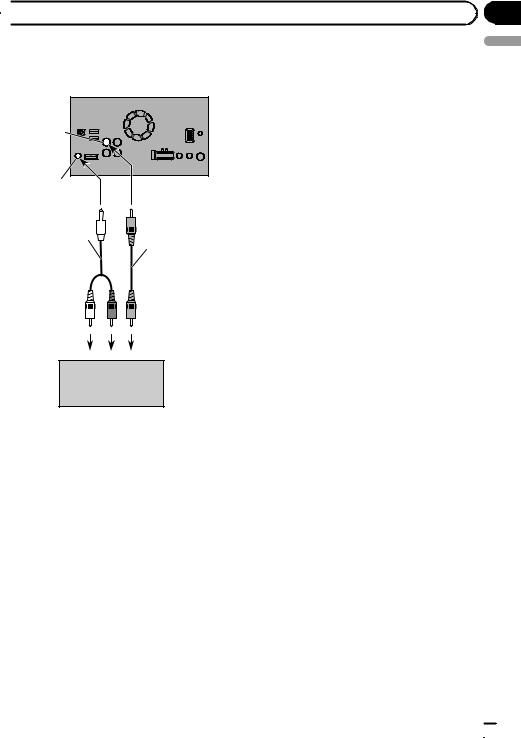
Connecting the external |
Connecting the video component |
video component |
This product |
Using AV input
You can connect an external video component or external camera to this product.
Connecting an external camera
This product |
15 cm |
|
23 cm |
||
|
||
|
Yellow |
|
Red, white |
(VIDEO INPUT |
|
(AUDIO INPUT) |
OR CAMERA |
|
|
INPUT) |
Section
02
English
15 cm
RCA cables (sold separately)
Yellow |
|
|
|
(VIDEO INPUT |
To audio outputs |
To video output |
|
OR CAMERA |
|||
|
|
||
INPUT) |
|
|
RCA cable (sold separately)
To video output
External camera (sold separately)
 Note
Note
This mode is available when the setting of AV input is set to “Camera”. (For details, refer to Operation Manual.)
External video component (sold separately)
 Note
Note
This mode is available when the setting of AV input is set to “Source”. (For details, refer to Operation Manual.)
Engb  17
17

Section
02  Connection
Using an AUX input
CAUTION
This product
AUX input
Mini-jack AV cable (CD-RM10)
(sold separately)
Yellow |
Red, white |
Be sure to use a mini-jack AV cable (CD-RM10) (sold separately) for wiring. If you use other cables, the wiring position might differ resulting in disturbed images and sounds.
OK |
|
|
|
|
L : Left audio (White) |
L |
L |
R : Right audio (Red) |
V G R |
R G V |
V : Video (Yellow) |
G : Earth |
|
RCA cables |
|
(sold separately) |
To video output |
To audio outputs |
|
External video |
|
component |
|
(sold separately) |
 Notes
Notes
!This mode is available when the setting of AUX input is set to “On”. (For details, refer to Operation Manual.)
!When connecting an external video component using a mini-jack AV cable, use a separately sold AUX extension cable as necessary.
 18
18 Engb
Engb
 Connection
Connecting the rear display
|
This product |
Yellow (V OUT) |
|
Rear audio |
|
output |
|
Mini pin plug cable |
|
(sold separately) |
RCA cable |
|
(sold separately) |
To audio inputs |
To video input |
Rear display with RCA input jacks (sold separately)
When using a rear display connected to rear video output
 WARNING
NEVER install the rear display in a location that enables the driver to watch the video source while driving.
This product’s rear video output is for connection of a display to enable passengers in the rear seats to watch the video source.
Section
02
English
Engb  19
19

Section |
|
|
|
|
03 |
|
Installation |
|
|
|
|
|
|
|
|
Precautions before |
! Do not install this product where it may (i) |
||
|
installation |
obstruct the driver’s vision, (ii) impair the |
||
|
performance of any of the vehicle’s oper- |
|||
|
|
|
||
|
|
CAUTION |
ating systems or safety features, includ- |
|
|
|
ing airbags, hazard lamp buttons or (iii) |
||
|
! Never install this product in places where, |
|||
|
impair the driver’s ability to safely oper- |
|||
|
|
or in a manner that: |
||
|
|
ate the vehicle. |
||
|
|
— Could injure the driver or passengers if |
||
|
|
! Install this product between the driver’s |
||
|
|
the vehicle stops suddenly. |
||
|
|
seat and front passenger seat so that it |
||
|
|
— May interfere with the driver’s opera- |
||
|
|
will not be hit by the driver or passenger if |
||
|
|
tion of the vehicle, such as on the floor |
||
|
|
the vehicle stops quickly. |
||
|
|
in front of the driver’s seat, or close to |
||
|
|
! Never install this product in front of or |
||
|
|
the steering wheel or gearstick. |
||
|
|
next to the place in the dashboard, door, |
||
|
! Make sure there is nothing behind the |
|||
|
or pillar from which one of your vehicle’s |
|||
|
|
dashboard or panelling when drilling |
||
|
|
airbags would deploy. Please refer to your |
||
|
|
holes in them. Be careful not to damage |
||
|
|
vehicle’s owner’s manual for reference to |
||
|
|
fuel lines, brake lines, electronic compo- |
||
|
|
the deployment area of the frontal air- |
||
|
|
nents, communication wires or power |
||
|
|
bags. |
||
|
|
cables. |
||
|
|
! Failure to follow all of these precautions |
||
|
! When using screws, do not allow them to |
|||
|
may result in serious injury or death. |
|||
|
|
come into contact with any electrical lead. |
||
|
|
|
|
|
|
|
Vibration may damage wires or insulation, |
|
|
|
|
leading to a short circuit or other damage |
To avoid electromagnetic |
|
|
|
to the vehicle. |
||
|
! To ensure proper installation, be sure to |
interference |
||
|
|
use the supplied parts in the manner spe- |
In order to prevent interference, set the follow- |
|
|
|
cified. If any parts are not supplied with |
||
|
|
ing items as far as possible from this product, |
||
|
|
this product, use compatible parts in the |
||
|
|
other cables or leads: |
||
|
|
manner specified after you have the parts’ |
||
|
|
! FM, MW/LW aerial and its lead |
||
|
|
compatibility checked by your dealer. If |
||
|
|
! GPS aerial and its lead |
||
|
|
parts other than supplied or compatible |
||
|
|
In addition, you should lay or route each aerial |
||
|
|
ones are used, they may damage internal |
||
|
|
lead as far as possible from other aerial leads. |
||
|
|
parts of this product or they may work |
||
|
|
Do not bind, lay or route them together, or |
||
|
|
loose and the product may become de- |
||
|
|
cross them. Electromagnetic noise will in- |
||
|
|
tached. |
||
|
|
crease the potential for errors in the vehicle’s |
||
|
! It is extremely dangerous to allow cables |
|||
|
location display. |
|||
|
|
to become wound around the steering col- |
||
|
|
|
|
|
|
|
umn or gearstick. Be sure to install this |
|
|
|
|
product, its cables, and wiring away in |
Before installing |
|
|
|
such so that they will not obstruct or hin- |
||
|
|
der driving. |
! Consult with your nearest dealer if installa- |
|
|
! Make sure that leads cannot get caught in |
tion requires drilling holes or other modifi- |
||
|
|
a door or the sliding mechanism of a seat, |
cations of the vehicle. |
|
|
|
resulting in a short circuit. |
! Before making a final installation of this |
|
|
! Please confirm the proper function of |
product, temporarily connect the wiring to |
||
|
|
your vehicle’s other equipment after in- |
confirm that the connections are correct |
|
|
|
stallation of this product. |
and the system works properly. |
|
 20
20 Engb
Engb
 Installation
Installing this product |
! When installing, to ensure proper heat dis- |
||
Installation notes |
persal when using this unit, make sure you |
||
leave ample space behind the rear panel |
|||
! Do not install this product in places subject |
and wrap any loose cables so they are not |
||
to high temperatures or humidity, such as: |
blocking the vents. |
||
— Places close to a heater, vent or air con- |
|
|
|
ditioner. |
|
|
|
— Places exposed to direct sunlight, such |
|
|
|
as on top of the dashboard. |
Leave ample |
|
|
— Places that may be exposed to rain, |
5 cm |
||
space |
|||
such as close to the door or on the vehi- |
|
|
|
cle’s floor. |
|
5 cm |
|
! Install this product in an area strong en- |
|
|
|
ough to bear its weight. Choose a position |
|
|
|
where this product can be firmly installed, |
! The cords must not cover the area shown |
||
and install it securely. If this product is not |
|||
in the figure below. This is necessary to |
|||
securely installed, the current location of |
|||
allow the amps and navigation mechanism |
|||
the vehicle cannot be displayed correctly. |
|||
to dissipate heat. |
|||
! Install this product horizontally on a sur- |
|||
|
|
||
face within 0 to 30 degrees tolerance (with- |
|
|
|
in 5 degrees to the left or right). Improper |
|
|
|
installation of the unit with the surface |
|
|
|
tilted more than these tolerances increases |
|
|
|
the potential for errors in the vehicle’s loca- |
|
|
|
tion display, and might otherwise cause re- |
|
|
|
duced display performance. |
|
|
|
Section
03
English
Do not cover this area.
! The semiconductor laser will be damaged if it overheats, so don’t install this product anywhere hot — for instance, near a heater
outlet.
30°
5° |
5° |
Parts supplied |
|
This product |
Truss head screw |
|
(5 mm × 8 mm) |
|
(6 pcs.) |
Engb  21
21

Section
03  Installation
Flush surface screw (5 mm × 9 mm)
(6 pcs.)
Installation using the screw holes on the side of this product
% Fastening this product to the factory radio-mounting bracket.
Position this product so that its screw holes are aligned with the screw holes of the bracket, and tighten the screws at three locations on each side.
Use either the truss head screws (5 mm × 8 mm) or flush surface screws (5 mm ×
9 mm), depending on the shape of the bracket’s screw holes.
If the pawl interferes with installation, you may bend it down out of the way.
1
3
2
1Factory radio-mounting bracket
2Dashboard or console
3Truss head screw or flush surface screw
Be sure to use the screws supplied with this product.
 22
22 Engb
Engb

 Installation
Installing the GPS aerial |
Parts supplied |
|
CAUTION |
|
|
Do not cut the GPS aerial lead to shorten it |
|
|
or use an extension to make it longer. Alter- |
|
|
ing the aerial cable could result in a short cir- |
GPS aerial |
Metal sheet |
cuit or malfunction and permanent damage |
||
to this product. |
|
|
Installation notes
!The aerial should be installed on a level surface where radio waves will be blocked as little as possible. Radio waves cannot be received by the aerial if reception from the satellite is blocked.
Section
03
English
1 2
1Dashboard
2Rear shelf
!When installing the GPS aerial inside the vehicle, be sure to use the metal sheet provided with your system. If this is not used, the reception sensitivity will be poor.
!Do not cut the accessory metal sheet. This would reduce the sensitivity of the GPS aerial.
!Take care not to pull the aerial lead when removing the GPS aerial. The magnet attached to the aerial is very powerful, and the lead may become detached.
!Do not paint the GPS aerial, as this may affect its performance.
Engb  23
23
Section
03  Installation
When installing the aerial inside the vehicle (on the dashboard or rear shelf)
 WARNING
Do not install the GPS aerial over any sensors or vents on the dashboard of the vehicle, as doing so may interfere with the proper functioning of such sensors or vents and may compromise the ability of the metal sheet under the GPS aerial to properly and securely affix to the dashboard.
1GPS aerial
2Metal sheet
Peel off the protective sheet on the rear.
3Clamps
Use separately sold clamps to secure the lead
where necessary inside the vehicle.
Affix the metal sheet on the surface as level as possible where the GPS aerial faces the window. Place the GPS aerial on the metal sheet. (The GPS aerial is fastened with its magnet.)
1 2
Make sure the surface is free of moisture, dust, grime, oil, etc., before affixing the metal sheet.
 Note
Note
The metal sheet contains a strong adhesive which may leave a mark on the surface if it is removed.
3
 Notes
Notes
!When attaching the metal sheet, do not cut it into small pieces.
!Some models use window glass that does not allow signals from GPS satellites to pass through. On such models, install the GPS aerial on the outside of the vehicle.
 24
24 Engb
Engb

 Installation
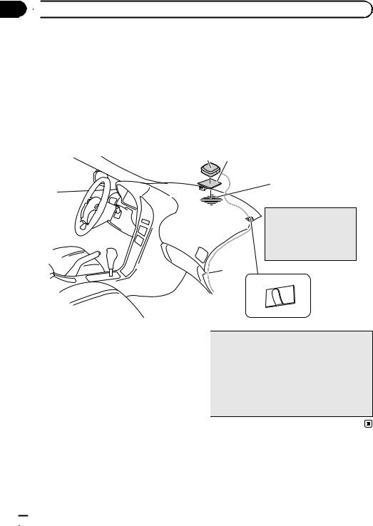
Installing the microphone |
2 Attach the microphone clip to the sun |
|
! Install the microphone in a place where its |
visor. |
|
1 |
||
direction and distance from the driver |
||
make it easiest to pick up the driver’s voice. |
|
|
! Be sure to turn off (ACC OFF) the product |
|
|
before connecting the microphone. |
|
Parts supplied
2
Section
03
English
Microphone |
Double-sided tape |
Mounting on the sun visor
1 Fit the microphone lead into the groove.
1
1Microphone clip
2Clamps
Use separately sold clamps to secure the lead where necessary inside the vehicle.
Install the microphone on the sun visor when it is in the up position. It cannot recognise the driver’s voice if the sun visor is in the down position.
2
1Microphone lead
2Groove
Engb  25
25
Section
03  Installation
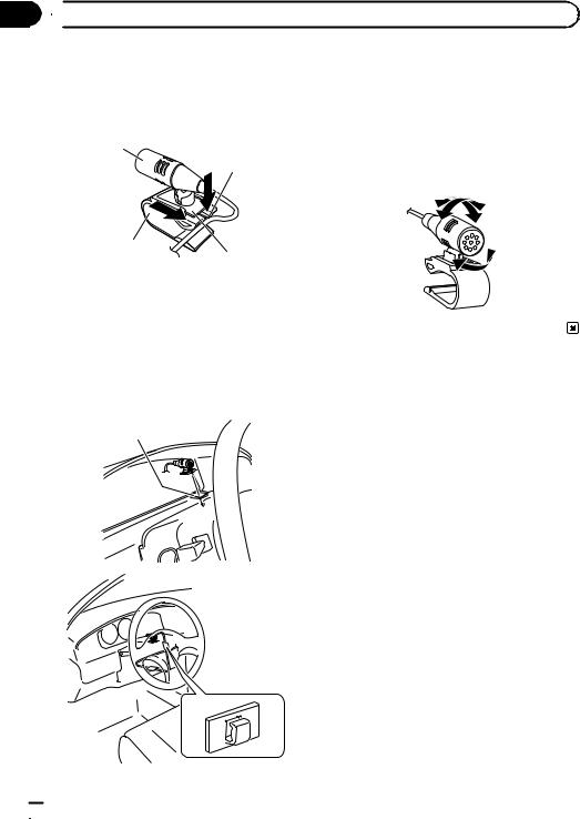
Installation on the steering column
1 Detach the microphone base from the microphone clip by sliding the microphone base while pressing the tab.
1
2
4
3
1Microphone
2Tab
3Microphone base
4Microphone clip
1Double-sided tape
2Clamps
Use separately sold clamps to secure the lead where necessary inside the vehicle.
Adjusting the microphone angle
The microphone angle can be adjusted.
2 Mount the microphone on the steering column.
Install the microphone on the steering column, keeping it away from the steering wheel.
1
2
 26
26 Engb
Engb

 After installation
After installing this product
1Reconnect the negative (–) terminal of the vehicle’s battery.
First, double-check that all connections are correct and that this product is installed correctly. Reassemble all vehicle components that you previously removed. Then reconnect the negative (–) cable to the negative (–) terminal of the battery.
2Start the engine.
3Press the RESET button.
Press the RESET button on this product with a pointed object such as the tip of a pen.
pSome of the settings and recorded contents will not be reset.
4Change the settings as desired.
=For details concerning operations, refer to Operation Manual.
5Drive down an unobstructed road until the GPS starts receiving the signal normally.
 Note
Note
After installing this product, be sure to check at a safe place that the vehicle is performing normally.
Section
04
English
Engb  27
27


 Sommaire
 Précautions
Votre nouveau produit et ce manuel 29 Importantes mesures de sécurité 29
 Connexion
Précautions à prendre avant de brancher le système 31
Avant d’installer ce produit 31 Pour éviter toute détérioration 32
–Remarque concernant le fil bleu/ blanc 32
Pièces fournies 33
Branchement du cordon d’alimentation
(1) 34
Branchement du cordon d’alimentation
(2) 36
Branchement du système 38
Connexion à un amplificateur de puissance vendu séparément 39
Connexion d’un iPhone avec connecteur Lightning 40
– Connexion via le port USB 40 Connexion d’un iPhone avec connecteur à
30broches |
40 |
|
|
|
|
– |
Connexion via l’entrée AUX |
40 |
|
||
– |
Connexion via l’entrée RGB |
41 |
|
||
Connexion d’un périphérique |
|
|
|
||
MirrorLink™ |
41 |
|
|
|
|
Connexion d’une caméra de rétrovisée |
42 |
||||
Connexion d’un élément vidéo externe |
43 |
||||
– |
Utilisation de l’entrée AV |
43 |
|
|
|
– |
Utilisation d’une entrée AUX |
44 |
|
||
Connexion de l’afficheur arrière |
45 |
|
|||
– Utilisation d’un écran arrière raccordé |
|||||
|
à la sortie vidéo arrière 45 |
|
|
||
Installation |
|
|
|
|
|
Précautions à prendre avant |
|
|
|
||
l’installation |
46 |
|
|
|
|
Pour éviter les parasites |
|
|
|
||
électromagnétiques |
46 |
|
|
|
|
Avant de procéder à l’installation |
47 |
||||
Installation de ce produit |
47 |
|
|
||
– |
Remarques sur l’installation |
47 |
|||
– |
Pièces fournies |
48 |
|
|
|
– |
Installation en utilisant les trous de vis |
||||
|
sur les côtés de ce produit |
48 |
|||
Installation de l’antenne GPS |
49 |
|
|||
– |
Remarques sur l’installation |
49 |
|||
– |
Pièces fournies |
49 |
|
|
|
– |
Installation de l’antenne dans le |
||||
|
véhicule (sur le tableau de bord ou la |
||||
|
lunette arrière) |
50 |
|
|
|
Installation du microphone |
51 |
|
|||
– |
Pièces fournies |
51 |
|
|
|
– |
Installation sur le pare-soleil |
51 |
|||
– |
Installation sur la colonne de |
||||
|
direction 52 |
|
|
|
|
– |
Réglage de l’angle du microphone 52 |
||||
Après l’installation |
|
|
|
|
|
Après avoir installé ce produit |
53 |
||||
 28
28 Fr
Fr

|
Section |
Précautions |
01 |
Votre nouveau produit et |
Importantes mesures de |
ce manuel |
sécurité |
!La fonction de navigation de ce produit (et la caméra de rétrovisée en option le cas échéant) est uniquement destinée à vous assister lors de la conduite de votre véhicule. Elle n’autorise en aucun cas un relâchement de votre attention, de votre jugement et de votre vigilance pendant la conduite.
!N’utilisez jamais ce produit pour joindre des hôpitaux, postes de police ou établissements similaires en cas d’urgence. Appelez le numéro d’urgence approprié.
!N’utilisez pas ce produit, n’importe quelle application ou la caméra de rétrovisée en option (le cas échéant) si celui-ci risque d’une façon ou d’une autre de détourner votre attention. Observez toujours les règles de sécurité et respectez toujours les réglementations de la circulation routière en vigueur. Si vous éprouvez des difficultés à utiliser ce produit ou à lire l’écran, garez votre véhicule en lieu sûr et serrez le frein à main avant d’effectuer les réglages nécessaires.
!Ce manuel explique comment installer ce produit dans votre véhicule. Le fonctionnement de ce produit est expliqué dans les manuels séparés.
!N’installez pas ce produit dans un endroit où il risque (i) d’entraver la visibilité du conducteur, (ii) d’altérer le fonctionnement de certains systèmes de commande des dispositifs de sécurité du véhicule, y compris les airbags ou les touches de feux de détresse, ou (iii) d’empêcher le conducteur de conduire le véhicule en toute sécurité. Dans certains cas, il peut ne pas être possible d’installer ce produit en raison du
type de véhicule ou de la forme de l’intérieur du véhicule.
 AVERTISSEMENT
Pioneer vous recommande de ne pas installer ce produit vous-même. Ce produit doit être exclusivement installé par un professionnel. Nous recommandons que seul le personnel d’entretien Pioneer agréé, qui dispose d’une formation et d’une expérience spéciales dans l’électronique mobile, configure et installe ce produit. N’INTERVENEZ JAMAIS SUR CE PRODUIT VOUS-MÊME. L’installation ou l’entretien de ce produit et de ses câbles de connexion peut vous exposer à un risque de choc électrique ou à d’autres dangers, et peut entraîner des dommages du produit non couverts par la garantie.
!Lisez attentivement le contenu de ce manuel avant d’installer ce produit.
!Conservez ce manuel à portée de main pour vous y reporter ultérieurement.
!Tenez compte de tous les avertissements formulés dans ce manuel et respectez soigneusement les consignes.
!Dans certaines circonstances, ce produit peut ne pas afficher la position correcte de votre véhicule, la distance des objets affichés à l’écran et les directions. Le système présente en outre certaines restrictions, notamment l’incapacité d’identifier les rues à sens unique, des limitations temporaires du trafic et des zones potentiellement dangereuses. Adoptez les mesures nécessaires en fonction des conditions de conduite réelles.
!Comme tout autre accessoire intérieur de votre véhicule, ce produit ne doit pas vous distraire de la bonne conduite de votre véhicule au risque d’entraîner des blessures graves voire mortelles. Si vous éprouvez des difficultés à utiliser le système ou à lire l’afficheur, procédez aux réglages lorsque le véhicule à l’arrêt.
Français
Fr  29
29

Section
01  Précautions
!Veillez à toujours porter votre ceinture de sécurité sur la route. En cas d’accident, le port de la ceinture peut réduire considérablement la gravité des blessures.
!Certaines lois nationales ou gouvernementales peuvent interdire ou restreindre l’emplacement et l’utilisation de ce produit dans votre véhicule. Veuillez vous conformer à toutes les lois et réglementations en
vigueur concernant l’utilisation, l’installation et le fonctionnement de ce produit.
 30
30 Fr
Fr
 Loading...