


INSTALLATION MANUAL
AVIC-N3
This product conforms to CEMA cord colors.
Le code de couleur des câbles utilisé pour ce produit est conforme à CEMA.
MANUEL |
Français English |
D’INSTALLATION |
|

IMPORTANT INFORMATION
ABOUT YOUR NEW NAVIGATION SYSTEM AND THIS MANUAL
•The navigation features of this product (and rear view camera option if purchased) is intended solely as an aid to you in the operation of your vehicle. It is not a substitute for your attentiveness, judgment and care when driving.
•Never use this navigation system to route to hospitals, police stations, or similar facilities in an emergency, Please call 911.
•Do not operate this navigation system (or the rear view camera option if purchased) if doing so in any way will divert your attention from the safe operation of your vehicle. Traffic restrictions and advisories currently in force should always take precedence over guidance given by this product. Always obey current traffic restrictions, even if this product provides contrary advice.
•Certain government laws may restrict the placement and use of navigation systems in your vehicle. Please comply with all applicable laws and regulations in the installation and operation of your navigation system.
•This manual explains how to install this navigation system in your vehicle. Operation of this navigation system is explained in the separate Operation Manual or Hardware Manual for the navigation system.
•Do not install the display unit or Hide-away unit where it may (i) obstruct the driver’s vision, (ii) impair the performance of any of the vehicle’s operating systems of safety features, including airbags, hazard lamp buttons or (iii) impair the driver’s ability to safely operate the vehicle. In some cases, it may not be possible to install this product because of the vehicle type or the shape of the vehicle interior.
1

Contents |
|
IMPORTANT INFORMATION .................... |
1 |
ABOUT YOUR NEW NAVIGATION |
|
SYSTEM AND THIS MANUAL .............. |
1 |
IMPORTANT SAFEGUARDS .................... |
3 |
PLEASE READ ALL OF THESE |
|
INSTRUCTIONS REGARDING |
|
YOUR NAVIGATION |
|
SYSTEM AND RETAIN THEM |
|
FOR FUTURE REFERENCE .................... |
3 |
Connecting the System ............................ |
4 |
- Before installing this product |
|
- To prevent damage |
|
- Parts supplied |
|
Connecting the system ...................................... |
7 |
Connecting the power cord (1) .......................... |
9 |
Connecting the power cord (2) ........................ |
11 |
When connecting to separately sold power |
|
amp .......................................................... |
13 |
When connecting a Rear view camera ............ |
15 |
When connecting the external video component |
|
and the display .......................................... |
16 |
-When using a display connected to rear video output
Installation ................................................ |
17 |
|
|
To guard against electromagnetic |
|
|
|
interference .............................................. |
18 |
|
|
Before installing .............................................. |
18 |
|
|
Installing the display unit and |
|
English |
|
Hide-away unit |
19 |
||
|
|||
- Installation notes |
|
|
|
- Parts supplied |
|
|
|
- Installing the Hide-away unit |
|
|
|
- DIN Front/Rear-mount |
|
|
|
- DIN Front-mount |
|
|
|
- DIN Rear-mount |
|
|
|
- Fixing the front panel |
|
Español |
|
- When installing the antenna inside the vehi- |
|||
Installing the GPS antenna .............................. |
26 |
|
|
- Installation notes |
|
|
|
- Parts supplied |
|
|
|
cle (on the rear shelf) |
|
|
|
- When installing the antenna outside the vehi- |
|
||
cle (on the body) |
|
Deutsch |
|
After Installing this Product |
29 |
||
|
|||
|
|
Français |
|
|
|
Italiano |
|
|
|
Nederlands |
|
2
IMPORTANT SAFEGUARDS
PLEASE READ ALL OF THESE INSTRUCTIONS REGARDING YOUR NAVIGATION SYSTEM AND RETAIN THEM FOR FUTURE REFERENCE
1.Read this manual fully and carefully before installing your navigation system.
2.Keep this manual handy for future reference.
3.Pay close attention to all warnings in this manual and follow the instructions carefully.
4.This navigation system may in certain circumstances display erroneous information regarding the position of your vehicle, the distance of objects shown on the screen, and compass directions. In addition, the system has certain limitations, including the inability to identify one-way streets, temporary traffic restrictions and potentially unsafe driving areas. Please exercise your own judgment in the light of actual driving conditions.
5.As with any accessory in your vehicle’s interior, the navigation system should not divert your attention from the safe operation of your vehicle. If you experience difficulty in operating the system or reading the display, please make adjustments while safely parked.
6.Please remember to wear your seat belt at all times while operating your vehicle. If you are ever in an accident, your injuries can be considerably more severe if your seat belt is not properly buckled.
Do not attempt to install or service your navigation system by yourself. Installation or servicing of the navigation system by persons without training and experience in electronic equipment and automotive accessories may be dangerous and could expose you to the risk of electric shock or other hazards.
3
Connecting the System
|
|
|
|
|
• |
Pioneer does not recommend that you install your navigation system yourself. We |
|
||
|
recommend that only authorized Pioneer service personnel, who have special train- |
|
||
|
ing and experience in mobile electronics, set up and install this product. NEVER |
English |
||
|
SERVICE THIS PRODUCT YOURSELF. Installing or servicing this product and |
|||
|
|
|||
|
its connecting cables may expose you to the risk of electric shock or other hazards, |
|
||
|
and can cause damage to the navigation system that is not covered by warranty. |
|
||
|
|
|
|
|
|
|
|
|
|
• |
If you decide to perform the installation yourself, and have special training and |
|
||
|
experience in the mobile electronics installations, please carefully follow all of the |
Español |
||
|
steps in the Installation Manual. |
|||
|
|
|||
• |
Secure all wiring with cable clamps or electrical tape. Do not allow any bare wiring |
|
||
|
to remain exposed. |
|
||
• Do not directly connect the yellow lead of this product to the vehicle battery. If the |
|
|||
|
lead is directly connected to the battery, engine vibration may eventually cause the |
|
||
|
insulation to fail at the point where the wire passes from the passenger compart- |
|
||
|
ment into the engine compartment. If the yellow lead’s insulation tears as a result |
Deutsch |
||
|
of contact with metal parts, short-circuiting can occur, resulting in considerable |
|||
|
|
|||
|
danger. |
|
||
• |
It is extremely dangerous to allow the GPS antenna cable or microphone cable to |
|
||
|
become wound around the steering column or shift lever. Be sure to install this |
|
||
|
product, its cables, and wiring away in such a way that they will not obstruct or |
|
||
|
hinder driving. |
|
||
• |
Make sure that the cables and wires are routed and secured so they will not inter- |
|
||
• |
fere with or become caught in any of the vehicle’s moving parts, especially the |
Français |
||
Do not route wires where they will be exposed to high temperatures. If the insula- |
||||
|
steering wheel, shift lever, parking brake, sliding seat tracks, doors, or any of the |
|
||
|
vehicle’s controls. |
|
||
|
tion heats up, wires may become damaged, resulting in a short circuit or malfunc- |
|
||
|
tion and permanent damage to the product. |
|
||
• |
Do not cut the GPS antenna cable to shorten it or use an extension to make it |
|
||
• |
longer. Altering the antenna cable could result in a short circuit or malfunction. |
Italiano |
||
Never feed power to other electronic products by cutting the insulation of the |
||||
• Do not shorten any leads. If you do, the protection circuit (fuse holder, fuse resister |
|
|||
|
or filter, etc.) may fail to work properly. |
|
||
|
power supply lead of the navigation system and tapping into the lead. The current |
|
||
|
capacity of the lead will be exceeded, causing overheating. |
|
||
• |
The black lead is ground. Please ground this lead separately from the ground of |
|
||
|
high-current products such as power amps. Do not ground more than one product |
Nederlands |
||
|
together with the ground from another product. For example, you must separately |
|||
|
|
|||
ground any amplifier unit away from the ground of the Hide-away unit. Connecting grounds together can cause a fire and/or damage the products if their grounds became detached.
4
Connecting the System
Before installing this product
•This product is for vehicles with a 12-volt battery and negative grounding. Check the battery voltage of your vehicle before installation.
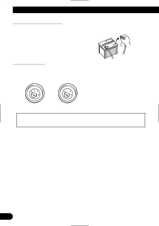
•To avoid shorts in the electrical system, be sure to disconnect the (–) battery cable before beginning installation.
To prevent damage
•When disconnecting a connector, pull the connector itself. Do not pull the lead, as you may pull it out of the connector.
•This product cannot be installed in a vehicle that does not have an ACC (accessory) position on the ignition switch.
O
FF
AC
C
O
N |
||
|
|
S |
|
|
T |
|
R |
A |
T |
|
|
O
FF
O
N |
||
|
|
S |
|
|
T |
|
R |
A |
T |
|
|
ACC position |
No ACC position |
•When the auto antenna function is used by connecting the blue lead to the vehicle with the auto antenna function, either turning off the ignition switch or detaching the front panel will retract the auto antenna of the vehicle.
•To avoid short-circuiting, cover the disconnected lead with insulating tape. It is especially important to insulate all unused speaker leads, which if left uncovered may cause a short circuit.
•Attach the connectors of the same color to the corresponding colored port, i.e., blue connector to the blue port, black to black, etc.
•Refer to the owner’s manual for details on connecting the power amp and other units, then make connections accordingly.
•When replacing the fuse, be sure to only use a fuse of the rating prescribed on the fuse holder.
•Since a unique BPTL circuit is employed, do not directly ground the ≠ side of the speaker lead or connect the ≠ sides of the speaker leads together. Be sure to connect the ≠ side of the speaker lead to the ≠ side of the speaker lead on the display unit.
•If the RCA pin jack on this product will not be used, do not remove the caps attached to the end of the connector.
5
•Never connect speakers with an output rating of less than 50 W channel or impedance outside of the 4 ohms to 8 ohms specifications to your navigation system. Connecting speakers with output and/or impedance values other than those noted here may result in
the speakers catching fire, emitting smoke, or becoming damaged.
•When the ignition switch is turned on (ACC ON), a control signal is output through the blue/white lead. Connect to an external power amp’s system remote control terminal (max. 300 mA 12 V DC). The control signal is output through the blue/white lead, even if the front panel is detached, or the audio source is switched off.
•When an external power amp is being used with this system, be sure not to connect the blue lead to the amp’s power terminal. Likewise, do not connect the blue lead to the power terminal of the auto antenna. Such connection could cause excessive current drain and malfunction as well as damage to the auto antenna of the vehicle.
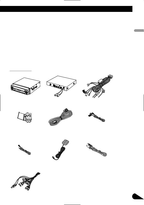
Parts supplied
Display unit |
Hide-away unit |
Power cord |
Connector |
30-pin cable |
Extension lead |
|
|
(for reverse signal) |
English
Español
Italiano Français Deutsch
Extension lead |
GPS antenna |
Extension antenna cable |
(for speed signal) |
|
|
Nederlands
System extension connector |
6 |
|

Connecting the System
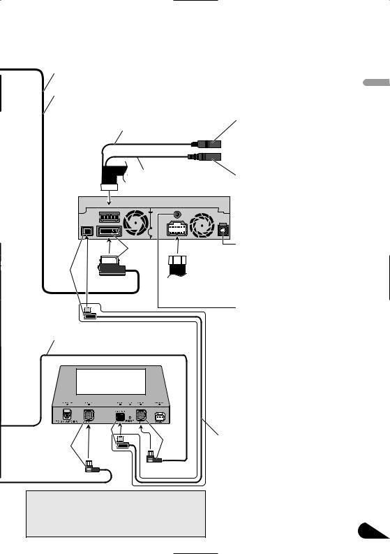
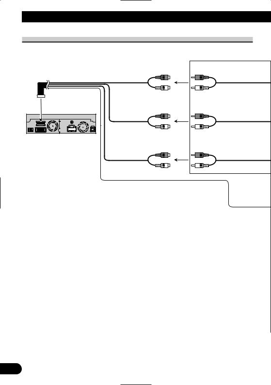
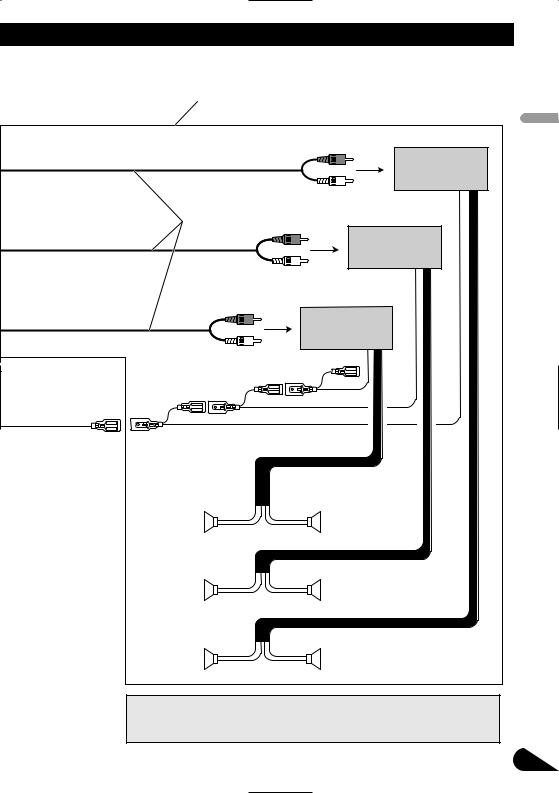
Connecting the system
|
|
Extension |
3 m (9 ft. 10 in.) |
|
|
antenna cable |
|
|
|
(supplied) |
|
Yellow |
Hide-away unit |
|
|
When installing |
|
|
|
the Hide-away unit |
|
|
|
in the trunk, etc., |
|
AV-BUS cable |
|
the extension cable |
|
||
|
(supplied with |
||
(e.g. CD-SC300E) |
|
||
|
TV tuner) |
|
|
(sold separately) |
*2 |
|
|
|
|
||
is required. |
|
|
|
|
|
|
|
Light gray |
Blue |
Blue |
Black |
5 m (16 ft. 5 in.) GPS antenna
•To avoid the risk of accident and the potential violation of applicable laws, this product should never be used while the vehicle is being driven except for navigation purposes. And, also Rear Displays should not be in a location where it is a visible distraction to the driver.
•In some countries or states the viewing of images on a display inside a vehicle even by persons other than the driver may be illegal. Where such regulations apply they must be obeyed and this product’s video source or TV features should not be used.
Hide-away TV tuner (e.g. GEX-P5700TV)
(sold separately)
Blue
Multi-CD player
(sold separately)
IP-BUS cable
iPod with Dock connector
Black |
IP-BUS cable  (supplied with TV tuner)
Black 

 Blue
Blue
 Dock connector
  port
port
iPod adapter (e.g. CD-IB100) (sold separately)
Dock connector (supplied with iPod adapter)
 IP-BUS cable (supplied with XM tuner)
7
|
|
|
|
|
|
|
|
|
|
|
|
|
|
|
|
Note: |
|
|||
30-pin cable (supplied) |
When Pioneer multi-channel processor (sold separately) is |
|||||
connected to this product, make sure the “5.1 CH” mode is |
||||||
|
|
|||||
|
|
activated. Please find the correct setting by referring to |
||||
3 m (9 ft. 10 in.) |
|
"Switching the 5.1ch setting" in the Operation Manual of the |
||||
|
|
navigation system. |
|
|||
|
|
|
|
|
|
|
|
20 cm (7-7/8 in.) |
WIRED REMOTE INPUT |
||||
|
Please see the Instruction |
|||||
|
|
|
|
|
Manual for the Wired Remote |
|
|
|
|
|
|
Control adapters (sold separately). |
|
|
|
|
|
|
||
English
 20 cm (7-7/8 in.)
MIC INPUT
Display unit
The microphone in the voice recognition kit (e.g. CD-VC1) (sold separately) is connected when the voice recognition function is used.
Yellow |
DIGITAL OUT |
|
This is used when connecting |
||
|
||
Black |
to the Pioneer multi-channel |
|
processor (sold separately), that is |
||
Power cord |
compatible with this product. |
|
Otherwise this is not used. |
||
|
||
|
G.SP (Guidance speaker output) |
|
|
This is not used normally. |
|
|
When combining this product with |
|
IP-BUS cable |
Pioneer multi-channel processor |
|
(sold separately) that is compatible |
||
(supplied with iPod adapter) |
||
with the product, G.SP will be |
||
|
||
|
used to output the guidance voice. |
|
Hide-away XM tuner |
In this case, the Pioneer external |
|
speaker (e.g. CD-TS37GP) (sold |
||
(GEX-P10XMT) |
||
separately) must be connected to |
||
(sold separately) |
||
|
the SP-OUT jack (2.5 ø MINI |
|
|
JACK, 1W max [16 Ω]). |
|
|
For details, see the operation |
|
Black |
manual of the external speaker. |
|
|
||
Blue |
XM DATA cable |
|
Black |
(supplied with XM tuner) |
|
|
||
|
• When combining this product with |
|
*1 |
GEX-P10XMT (sold separately), this |
|
|
connection must be required. |
|
|
• When installing the XM tuner in the |
|
Note: |
trunk, etc., the extension cable (e.g. CD- |
|
600DC) (sold separately) is required. |
||
The XM tuner will not receive XM Radio service when |
||
|
||
you drive outside of the XM's coverage area. When the |
|
|
XM tuner is not used, connect the IP-BUS cable*1 |
|
|
directly to the navigation's Hide-away unit*2. |
|
Español
Italiano Français Deutsch
Nederlands
8
Connecting the System
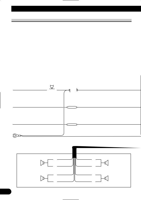
Connecting the power cord (1)
Fuse (10 A) |
|
|
|
|
|
||||
|
|
|
|
|
|
|
|
|
|
|
|
|
|
|
|
|
|
|
|
Yellow |
|
|
|
|
|
||||
To terminal always supplied |
|
|
|
|
|
||||
with power regardless of |
|
|
|
|
|
||||
ignition switch position. |
|
|
|
|
|
||||
Red |
Fuse resistor |
||||||||
|
|
|
|
|
|||||
To electric terminal controlled |
|
|
|
|
|
||||
by ignition switch (12 V DC) |
|
|
|
|
|
||||
ON/OFF. |
|
|
|
|
|
||||
Orange/white |
Fuse resistor |
||||||||
To lighting switch terminal. |
|
|
|
|
|
||||
Black (ground)
To vehicle (metal) body.
With a 2 speaker system, do not connect anything to the speaker leads that are not connected to speakers.
|
White |
Gray |
|
|
Front speaker |
+ |
+ |
Front speaker |
|
|
|
|||
|
≠ |
≠ |
|
|
Left |
White/black |
Gray/black |
Right |
|
Green |
Violet |
|||
|
|
|||
Rear speaker |
+ |
+ |
Rear speaker |
|
or Subwoofer |
≠ |
≠ |
or Subwoofer |
|
|
|
|||
|
Green/black |
Violet/black |
|
9
See Page 12.
GUIDE ON
SYSTEM REMOTE |
CONTROL |
See Page 13. |
Display unit
Note:
Cords for this product and those for other products may be different colors even if they have the same function. When connecting this product to another product, refer to the supplied manuals of both products and connect cords that have the same function.
Yellow/black
If you use equipment with a mute function (e.g. cellular telephones), connect that equipment to the Audio Mute lead. If not, keep the Audio Mute lead free of any connections.
Note:
Audio source will be set to mute or attenuate, while the voice guidance of the navigation will not be muted or attenuated. For details, see the Operation Manual.
Light green
See Page 11.
Note:
When the auto antenna function is used by connecting the blue lead to the vehicle with the auto antenna function, either turning off the ignition switch or detaching the front panel will retract the auto antenna of the vehicle.
Note:
When a subwoofer is connected to this product instead of a rear speaker, change the rear output setting in
the Initial Setting. (Refer to the Operation Manual.) The subwoofer output of this product is monaural.
Blue
To Auto-antenna relay control terminal. If the vehicle has a glass antenna, connect to the antenna booster power supply
terminal (max. 300 mA 12 V DC).
English
Español
Italiano Français Deutsch
Nederlands
10
Connecting the System
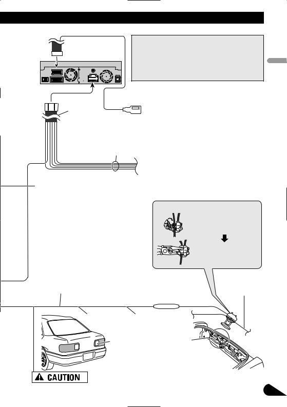
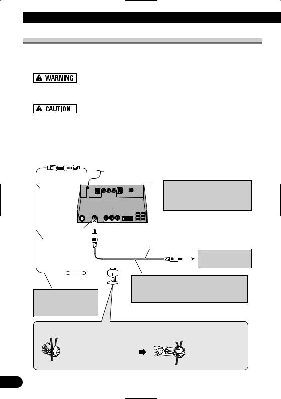
Connecting the power cord (2)
Speed detection circuit lead
Vehicle injection computer
Connector
Connection method
Pass the extension cord and the lead for the speed detection circuit through this hole.
Clamp firmly with  needle-nosed
pliers.
Close the cover.
Hide-away unit
Extension lead (for speed signal)
Note: The position of the speed detection circuit depends on the vehicle model. For details, consult your authorized Pioneer dealer or an installation professional.
If connection to the speed detection circuit is too difficult, connect the separately sold ND-PG1 speed pulse generator to the pink lead.
Note: The position of the parking brake switch depends on the vehicle model. For details, consult the vehicle owner’s manual or dealer.
Pink (CAR SPEED SIGNAL INPUT) |
5 m (16 ft. 5 in.) |
|
The mobile navigation system is connected here to detect the distance the vehicle travels. Always connect the vehicle’s speed detection circuit or the ND-PG1 speed pulse generator, sold separately. Failure to make this connection will increase errors in the location display.
IMPROPER CONNECTION MAY RESULT IN SERIOUS DAMAGE OR INJURY INCLUDING ELECTRICAL SHOCK, AND INTERFERENCE WITH THE OPERATION OF THE VEHICLE’S ANTILOCK BRAKING SYSTEM, AUTOMATIC TRANSMISSION AND SPEEDOMETER INDICATION.
Light green
Used to detect the ON/OFF status of the parking brake. This lead must be connected to the power supply side of the parking brake switch. If this connection is made incorrectly or omitted, certain functions of your navigation system will be unusable.
LIGHT GREEN LEAD AT POWER CONNECTOR IS DESIGNED TO DETECT PARKED STATUS AND MUST BE CONNECTED TO THE POWER SUPPLY SIDE OF THE PARKING BRAKE SWITCH. IMPROPER CONNECTION OR USE OF THIS LEAD MAY VIOLATE APPLICABLE LAW AND MAY RESULT IN SERIOUS INJURY OR DAMAGE.
Connection method
Clamp the parking brake switch power supply side lead. 
Clamp firmly with needle-nosed pliers.
Power supply side
Ground side
Parking brake switch
11
|
Note: |
Display unit |
Cords for this product and those for other products may |
|
be different colors even if they have the same function. |
|
When connecting this product to another product, refer |
|
to the supplied Installation manuals of both products |
|
and connect cords that have the same function. |
Yellow/black (GUIDE ON)
When combining this navigation system with the other Pioneer audio unit for the vehicle, if the vehicle
Power cord  stereo has yellow/black leads, connect them to those leads. In this way, when the guidance audio is output and when you operate the system by voice, the vehicle stereo is automatically muted to reduce the vehicle stereo volume.
Black, Orange/white, Red, Yellow
English
Español
See Page 9.
Violet/white (REVERSEGEAR SIGNAL INPUT)
This is connected so that the navigation system can detect whether the vehicle is moving forwards or backwards. Connect the violet/white lead to the lead whose voltage changes when the shift lever is put in reverse. Unless connected, the sensor may not detect your vehicle traveling forward/backward properly, and thus the position of your vehicle detected by the sensor may be misaligned from the actual position.
Note: When you use the ND-PG1 speed pulse generator (sold separately), please make sure
to connect it.
When you use a rear view camera, please make sure to connect it. Otherwise you cannot switch to rear view camera picture.
See Page 15.
Fuse resistor
Connection method
Clamp the reversing lamp lead.
Clamp firmly with needle-nosed pliers.
Reversing lamp lead
Extension lead |
5 m (16 ft. 5 in.) |
(for reverse signal) |
|
Italiano Français Deutsch
Check the position of your vehicle’s reversing lamp (the one that lights up when the shift lever is in reverse [R]) and find the reversing lamp lead in the trunk.
Be sure to use only the supplied extension lead. Use of another lead could cause fire, smoke and/or damage this product.
Nederlands
12
Connecting the System
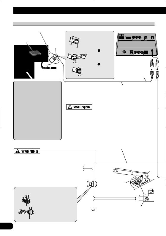
When connecting to separately sold power amp
|
Subwoofer output |
|
or non-fading output |
|
(SUBWOOFER OUTPUT or |
|
NON-FADING OUTPUT) |
|
20 cm (7–7/8 in.) |
|
Rear output |
|
(REAR OUTPUT) |
|
15 cm (5–7/8 in.) |
Display unit |
Front output |
|
|
|
(FRONT OUTPUT) |
15 cm (5–7/8 in.)
 Blue/white
To system control terminal of the power amp (max. 300 mA 12 V DC).
Do not connect this lead to Auto-antenna control terminal.
13
Perform these connections when using the optional amplifier.
Power amp (sold separately)
RCA cables (sold separately)
Power amp (sold separately)
Power amp (sold separately)
System remote control |
|
Left |
Right |
+ |
+ |
Front speaker |
Front speaker |
≠ |
≠ |
+ |
+ |
Rear speaker |
Rear speaker |
≠ |
≠ |
+ |
+ |
Subwoofer |
Subwoofer |
≠ |
≠ |
Note:
You can change the RCA output of the subwoofer depending on your subwoofer system. (Refer to the Operation Manual.)
English
Español
Italiano Français Deutsch
Nederlands
14
Connecting the System
When connecting a Rear view camera
When using this product with a rear view camera, automatic switching to video from a rear view camera is possible when the gear shift is moved to REVERSE (R) position.
Rear view mode also allows you to check what is behind you while driving.
USE INPUT ONLY FOR REVERSE OR MIRROR IMAGE REAR VIEW CAMERA. OTHER USE MAY RESULT IN INJURY OR DAMAGE.
•The screen image may appear reversed.
•The rear view camera function is to use this product as an aid to keep an eye on trailers, or backing into a tight parking spot. Do not use this function for entertainment purposes.
•The object in rear view may appear closer or more distant than in reality.
•Please note that the edges of the rear view camera images may differ slightly according to whether full screen images are displayed when backing, and whether the images are used for checking the rear when the vehicle is moving forward.
See Page 11.
5 m (16 ft. 5 in.)
Brown
Extension lead (for reverse signal)
Hide-away unit
Note:
It is necessary to set to “CAMERA” in “SETUP” when connecting the rear view camera.
RCA cable
(sold separately)
Rear view camera
To video output
Fuse resistor
Note:
Do not use other than the supplied extension lead.
Connection method
1. Clamp the lead.
Note:
Connect to the rear view camera. Do not connect to any other equipment.
2. Clamp firmly with needle-nosed pliers.
15
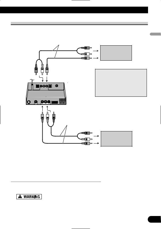
When connecting the external video component and the display
RCA cables |
|
(sold separately) |
To audio inputs |
|
Display with
RCA input jacks
To video input
Hide-away unit
RCA cables (sold separately)
Note:
The map screen navigation images output to the rear display differ from standard NTSC format images. Therefore, their quality will be inferior to the images that appear on the front display.
To audio outputs
External video component (sold separately)
To video output
•It is necessary to set to “AV INPUT” or “REAR DISP” in “SET UP” when connecting the external video component.
When using a display connected to rear video output
This product’s rear video output is for connection of a display to enable passengers in the rear seats to watch the video source.
•NEVER install the rear display in a location that enables the driver to watch the video source while Driving.
•NEVER connect rear audio output (REAR OUT) to separately sold power amp.
English
Español
Italiano Français Deutsch
Nederlands
16
Installation
•Pioneer does not recommend that you install or service your navigation system yourself. Installing or servicing the product may expose you to risk of electric shock or other hazards. Refer all installation and servicing of your navigation system to authorized Pioneer service personnel.
•Never install this product in places, or in a manner that where:
*It could injure the driver or passengers if the vehicle stops suddenly.
*It may interfere with the driver’s operation of the vehicle, such as on the floor in front of the driver’s seat, or close to the steering wheel or shift lever.
•Make sure there is nothing behind the dashboard or paneling when drilling holes in them. Be careful not to damage fuel lines, brake lines, electronic components, communication wires or power cables.
•When using screws, do not allow them to come into contact with any electrical lead. Vibration may damage wires or insulation, leading to a short circuit or other damage to the vehicle.
•To ensure proper installation, use the supplied parts in the manner specified. If any parts other than the supplied ones are used, they may damage internal parts of this product or they may work loose and the product may become detached.
•It is extremely dangerous to allow the GPS antenna lead or microphone lead to become wound around the steering column or shift lever. Be sure to install this product in such a way that it will not obstruct driving.
•Make sure that leads cannot get caught in a door or the sliding mechanism of a seat, resulting in a short circuit.
•Please confirm the proper function of your vehicle’s other equipment following installation of the navigation system.
•Certain government laws may prohibit or restrict the placement and use of this system in your vehicle. Please comply with all applicable laws and regulations regarding the use, installation and operation of your navigation system.
•Do not install the display unit or Hide-away unit where it may (i) obstruct the driver’s vision, (ii) impair the performance of any of the vehicle’s operating systems or safety features, including airbags, hazard lamp buttons or (iii)
17 |
impair the driver’s ability to safely operate the vehicle. |
|

•Install the display unit between the driver’s seat and front passenger seat so that it will not be hit by the driver or passenger if the vehicle stops quickly.
•Never install the display unit in front of or next to the place in the dash, door, or pillar from which one of your vehicle’s airbags would deploy. Please refer to your vehicle’s Owner’s Manual for reference to the deployment area of the frontal airbags.
•Do not install the display unit and Hide-away unit in a place where it will impair the performance of any of the vehicle’s operating systems, including airbags and headrests.
To guard against electromagnetic interference
•In order to prevent interference, set the following items as far as possible from the display unit and Hide-away unit of this navigation system, other cables or leads:
-TV antenna and antenna lead
-FM, AM antenna and its lead
-GPS antenna and its lead
In addition you should lay or route each antenna lead as far as possible from other antenna leads.
Do not bind them together, lay or route them together, or cross them.
Such electromagnetic noise will increase the potential for errors in the location display.
Before installing
•Consult with your nearest dealer if installation requires the drilling of holes or other modifications of the vehicle.
•Before making a final installation of this product, temporarily connect the wiring to confirm that the connections are correct and the system works properly.
English
Español
Italiano Français Deutsch
Nederlands
18
 Loading...