


AVIC-90DVD
AVIC-90DVD
ENGLISH
MANUEL D’INSTALLATION
FRANÇAIS DEUTSCH
This product conforms to CEMA cord colors.
Le code de couleur des câbles utilisé pour ce produit est
conforme à CEMA.
INSTALLATION MANUAL
ITALIANO NEDERLANDS

IMPORTANT INFORMATION
ABOUT YOUR NEW DVD NAVIGATION UNIT AND THIS MANUAL
• The Pioneer DVD Navigation Unit is intended solely as an aid to you in the operation of your car. It is not a substitute for your attentiveness, judgment and care
while driving.
• Do not use your navigation system to route you to emergency services such as
hospitals or police stations. Not all emergency service facilities are contained in
the map data.
• Do not operate the DVD Navigation Unit if doing so will divert your attention
from the safe operation of your car. Always observe safe driving rules and follow
all existing traffic regulations.
• Certain state laws may restrict the placement and use of navigation systems in
your car. Please comply with all applicable laws and regulations in the installation and operation of your navigation system.
• This manual explains how to install this DVD Navigation Unit in your car.
Operation of this DVD Navigation Unit is explained in the separate “Operation
Manual” that also came with this unit.
1

Contents
IMPORTANT SAFEGUARDS .................... 3
PLEASE READ ALL OF THESE
INSTRUCTIONS REGARDING
YOUR DVD NAVIGATION
UNIT AND RETAIN THEM
FOR FUTURE REFERENCE .................... 3
Connecting the System ............................ 5
CAUTION ........................................................ 5
-
Before installing the unit
-
To prevent damage
-
Parts supplied
Connecting the system ...................................... 7
-
Connecting to the display with 26-pin
RGB input (AVH-P6400CD,
AVH-P6400, etc.)
-
Connecting to the display with 20-pin
RGB input
Connecting the System
(In case of a display sold in the market) .... 9
Connecting the power cord (1) ........................ 11
Connecting the power cord (2) ........................ 13
Installation ................................................ 14
CAUTION ...................................................... 14
To guard against electromagnetic
interference ................................................15
Before installing and fixing ............................ 15
Before using the adhesive tape ........................ 15
Installing the main unit .................................... 16
-
Installation notes
-
Parts supplied
-
CAUTION
-
If you install with the left and right sides
of the DVD Navigation Unit parallel to
your car’s forward / backward direction
-
When installing the main unit inside the
trunk, on the floor under a seat, etc., using
tapping screws
-
CAUTION
-
DIN Rear-mount: Installation using the screw
holes on the side of the unit
Installing the GPS antenna .............................. 22
-
CAUTION
-
Installation notes
-
Parts supplied
-
When installing the antenna inside the
car (on the dashboard or rear shelf)
-
When installing the antenna outside the
car (on the body)
Installing the Remote controller ...................... 25
-
Parts supplied
-
Loading the batteries
-
CAUTION
-
Remote controller handling notes
-
When Installing with double-sided tape
Installing the microphone ................................ 27
-
Installation notes
-
Parts supplied
-
When installing the microphone on the
sun visor
-
When installing the microphone on the
steering column
-
CAUTION
ENGLISH ESPAÑOL DEUTSCH FRANÇAIS
ITALIANO NEDERLANDS
After installing the unit .......................... 30
2

IMPORTANT SAFEGUARDS
PLEASE READ ALL OF THESE INSTRUCTIONS REGARDING YOUR DVD
NAVIGATION UNIT AND RETAIN THEM FOR FUTURE REFERENCE
1. Read this manual fully and carefully before installing your DVD Navigation Unit.
2. Keep this manual handy for future reference.
3. Pay close attention to all warnings in this manual and follow the instructions carefully.
4. This unit is intended solely as an aid to you in the operation of your car. It is not a
substitute for your attentiveness, judgment and care while driving. Do not operate
your DVD Navigation Unit if doing so will divert your attention from the safe
operation of your car. Always observe safe driving rules and follow all existing
traffic regulations.
5. Certain state laws may restrict the placement and use of this system in your car.
Please comply with all applicable laws and regulations in the installation and
operation of your navigation system.
6. This DVD Navigation Unit may in certain circumstances display erroneous information regarding the position of your car, the distance of objects shown on the
screen, and compass directions. In addition, the system has certain limitations,
including the inability to identify one-way streets, temporary traffic restrictions
and potentially unsafe driving areas. Please exercise your own judgment in light
of actual driving conditions.
3

7. As with any accessory in your car’s interior, the DVD Navigation Unit should not
divert your attention from the safe operation of your car. If you experience difficulty in operating the system or reading the display, please make adjustments
while safely parked.
8. Do not attempt to install or service your DVD Navigation Unit by yourself.
Installation or servicing of the DVD Navigation Unit by persons without training
and experience in electronic equipment and automotive accessories may be dangerous and could expose you to the risk of electric shock or other hazards.
9. Please remember to wear your seat belt at all times while operating your car. If
you are ever in an accident, your injuries can be considerably more severe if your
seat belt is not properly buckled.
ENGLISH ESPAÑOL DEUTSCH FRANÇAIS
ITALIANO NEDERLANDS
4

Connecting the System
CAUTION
• Pioneer does not recommend that you install or service your DVD navigation
unit yourself. Installing or servicing of the product may expose you to risk of
electric shock or other hazards. Refer all installation and servicing of your
navigation unit to authorized Pioneer service personnel.
• Secure all wiring with cable clamps or electrical tape. Do not allow any bare
wiring to remain exposed.
• Do not drill a hole into the engine compartment to connect the yellow lead of
the unit to the car battery. Engine vibration may eventually cause the insulation to fail at the point where the wire passes from the passenger compartment into the engine compartment. Take extra care in securing the wire at
this point.
• It is extremely dangerous to allow the GPS antenna lead or microphone lead
to become wound around the steering column or shift lever. Be sure to install
the unit in such a way that it will not obstruct driving.
• Make sure that wires will not interfere with moving parts of the car, such as
the shift lever, parking brake or seat sliding mechanism.
• Do not route wires where they will be exposed to high temperatures. If the
insulation heats up, wires may become damaged, resulting in a short circuit
or malfunction.
• Do not cut the GPS antenna lead to shorten it or use an extension to make it
longer. Altering the antenna cable could result in a short circuit or malfunction.
• Do not shorten any leads. If you do, the protection circuit may fail to work
properly.
• Never feed power to other electronic products by cutting the insulation of the
power supply lead of the DVD navigation unit and tapping into the lead. The
current capacity of the lead will be exceeded, causing overheating.
5
Before installing the unit
• This unit is for cars with a 12-volt battery and negative grounding. Before installing it in
a recreational car, truck, or bus, check the battery voltage.
• To avoid shorts in the electrical system, be sure to disconnect the (-) battery cable before beginning installation.
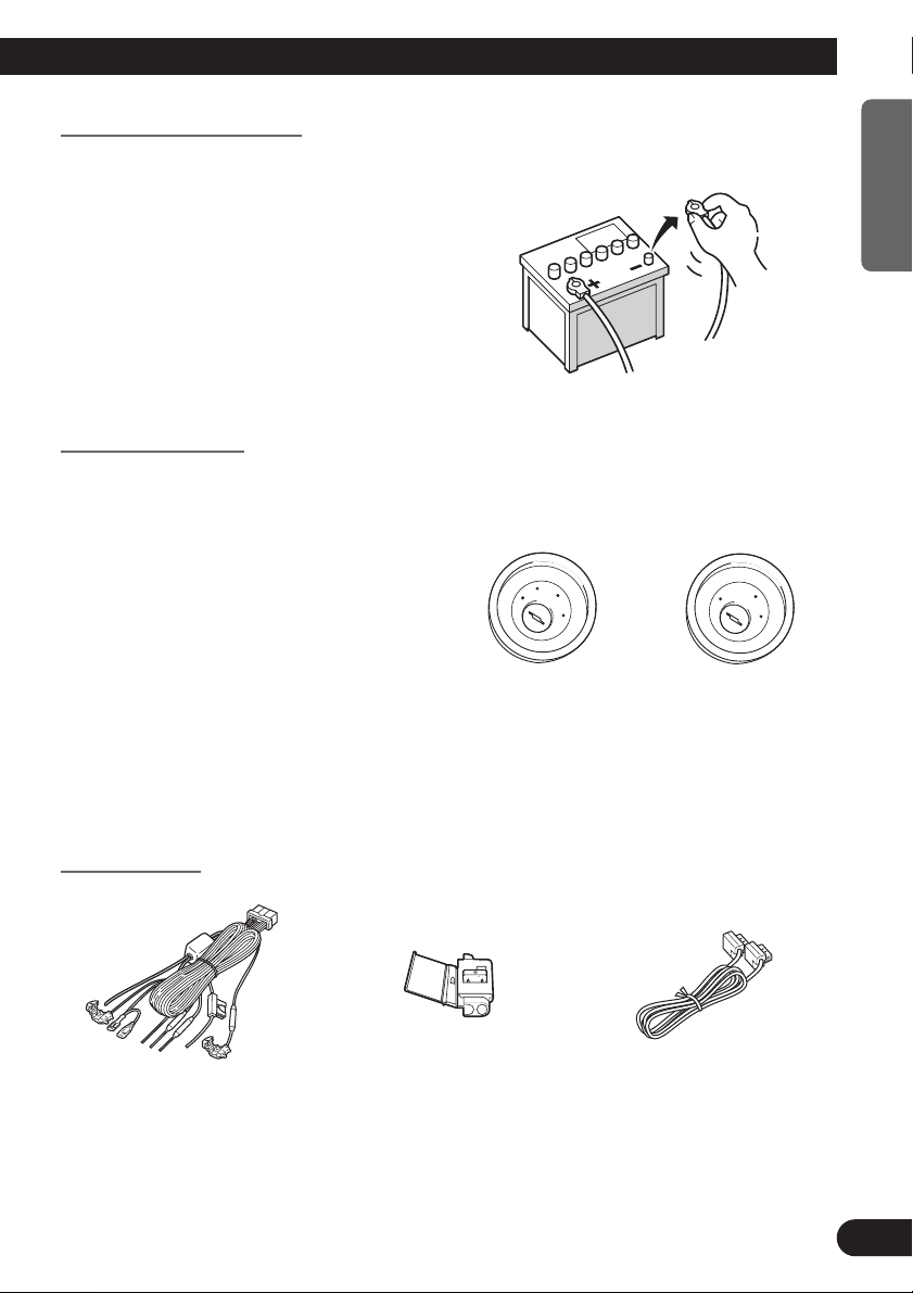
To prevent damage
• When disconnecting a connector, pull
the connector itself. Do not pull the
lead, as you may pull it out of the connector.
• If this unit is installed in a car that does
not have an ACC (accessory) position
on the ignition switch, the red lead of
the unit should be connected to a terminal coupled with ignition switch
ON/OFF operations. If this is not done,
the car battery may be drained when
you are away from the car for several
hours.
• To avoid short-circuiting, cover the
disconnected lead with insulating tape.
C
C
A
O
F
N
F
O
S
T
A
R
T
F
F
O
No ACC positionACC position
ENGLISH ESPAÑOL DEUTSCH FRANÇAIS
O
N
S
T
A
R
T
Parts supplied
ITALIANO NEDERLANDS
26 pin-RGB cableConnectorPower cord
6
Connecting the System
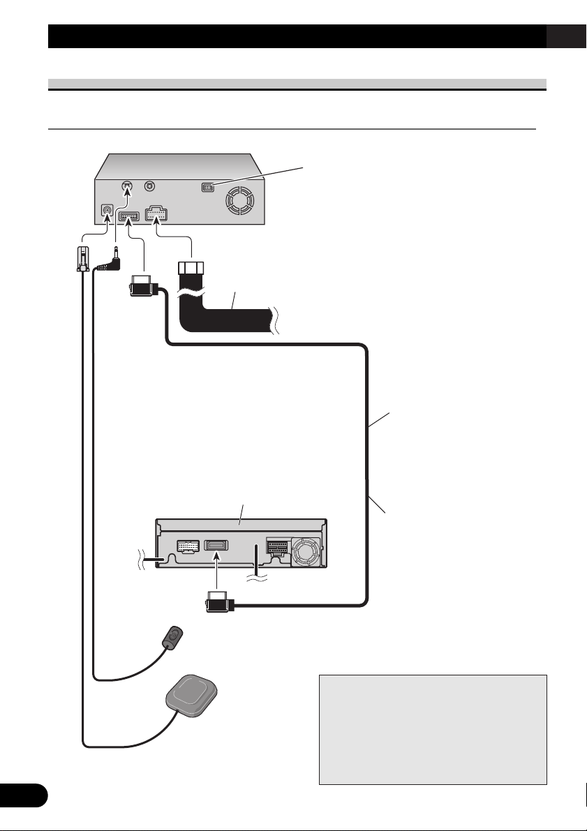
Connecting the system
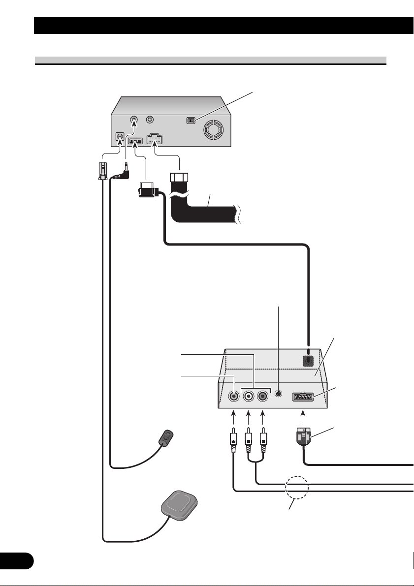
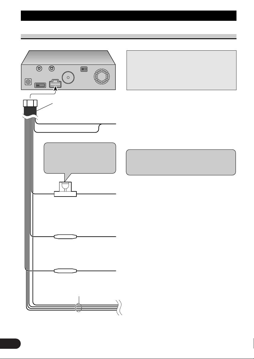
Connecting to the display with 26-pin RGB input (AVH-P6400CD, AVH-P6400, etc.)
Use this jack when connecting the CUE unit for
obtaining traffic information.
Power cord
See pages 11-13.
☞
26-pin RGB cable
(supplied)
(Ex. AVH-P6400CD, AVH-P6400)
6m (19ft 8in.)
Microphone
See page 27.
☞
When resetting AV Head Unit
GPS antenna
See page 22.
☞
When pressing the reset button of AV Head
Unit while Navigation System and AV Head
Unit (AVH-P6400CD, AVH-P6400) are combined, make sure that ACC is tuned OFF. If
the reset button is pressed while ACC is ON,
it may not work properly.
7
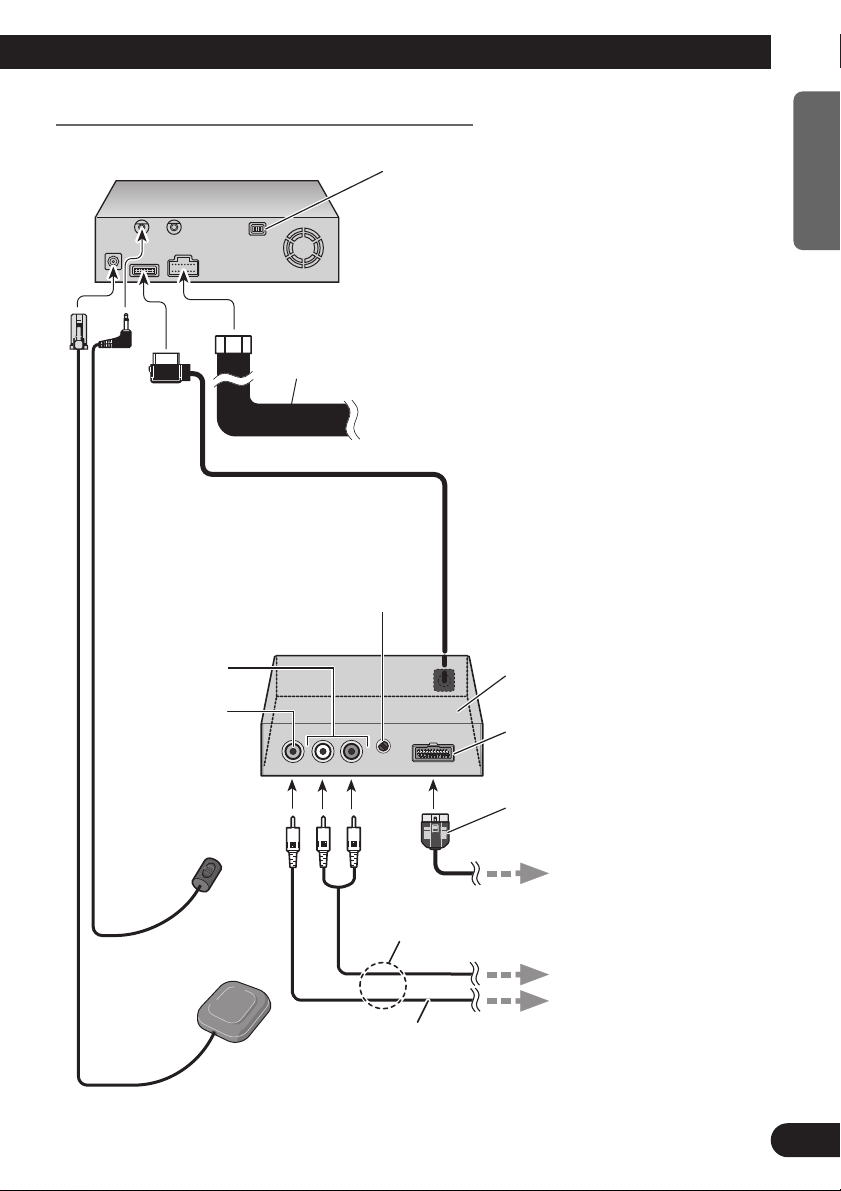
Connecting to the display with 20-pin RGB input
ENGLISH ESPAÑOL DEUTSCH FRANÇAIS
This product
Power cord
Level Control
This is used for adjusting output from Audio
Output. If you turn it to the right, the volume
increases, while turning it to the left reduces the
volume. (Normally, turn it fully to the right, and
instead use the external equipment outputting
sound, such as a display, for adjusting the volume.)
Audio output
Video output
Use this jack when connecting the CUE unit for obtaining
traffic information.
See page 11-13.
☞
CD-RGB26P
(sold separately)
Green
Microphone
See page 27.
☞
GPS aerial
See page 22.
☞
Green
RCA cable
(sold separately)
Please make sure to complete
this connection. Otherwise
you cannot see the image of
the DVD-Video.
ITALIANO NEDERLANDS
To RGB input of the display.
To Audio inputs.
To VTR input of the display.
8
Connecting the System
Connecting the System (In case of a display sold in the market)
Use this jack when connecting the
CUE unit for obtaining traffic information.
Power cord
See pages 11-13.
☞
Level Control
This is used for adjusting output from Audio Output. If
you turn it to the right, the volume increases, while turning
it to the left reduces the volume. (Normally, turn it fully to
the right, and instead use the external equipment outputting sound, such as a display, for adjusting the volume.)
CD-RGB26P
(Sold Separately)
Audio output
Video output
Green
Green
Microphone
See page 27.
☞
GPS aerial
See page 22.
☞
RCA cable (sold separately)
9
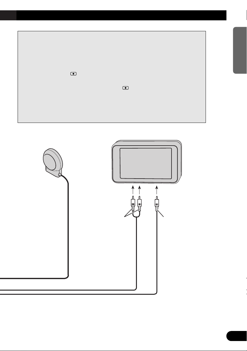
In order to output the image (RGB image) from RCA Video output (yellow)
when performing navigation, switching the image output is required.
1. Park your car in a safe place, and pull the side brake.
2. Turn the power of the main unit off (cut off the engine).
3. While pressing (AUDIO) button on the bottom left of the
numeric keypad of the Remote Controller, turn the ACC on
(start the engine). Keep pressing the (AUDIO) button until
the image is displayed on the screen.
Image output is switched, as the image of the navigation (RGB image) is output
from RCA Video output, and the image is displayed on the screen.
Voice Guidance
Speaker with infrared
sensor < ex.CD-TS36 >
(Sold Separately)
ENGLISH ESPAÑOL DEUTSCH FRANÇAIS
Display with RCA
input jacks
To Audio input
To Video input
ITALIANO NEDERLANDS
10
Connecting the System
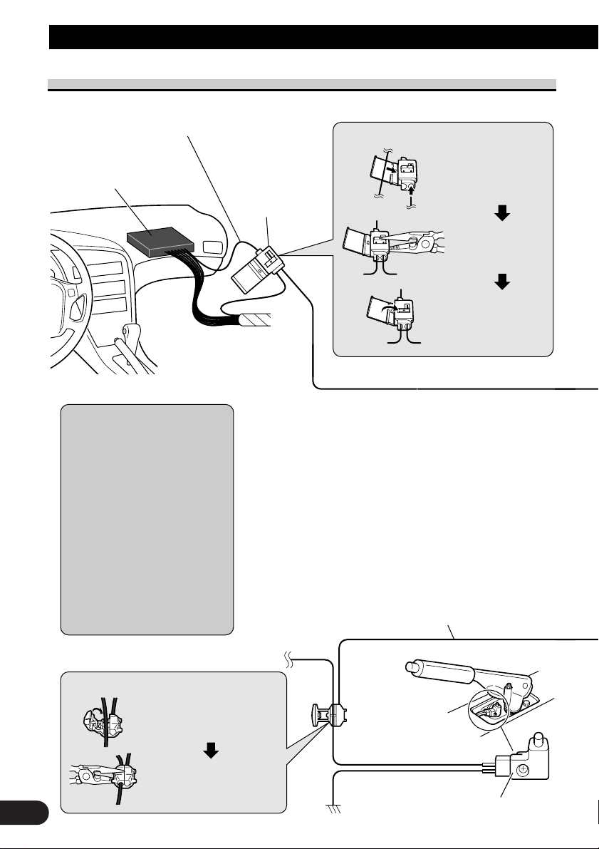
Connecting the power cord (1)
Speed detection circuit lead
Car injection computer
Note: The position of the speed
detection circuit depends on the car
model. For details, consult the relevant documents from Pioneer.
When making connections for a
model not listed in those documents or for which connection to
the speed detection circuit is too
difficult, connect the separately
sold ND-PG1 speed pulse generator to the pink lead.
Note: The position of the parking
brake switch depends on the car
model. For details, consult the car
owner’s manual or dealer.
Connection method
Pass the extension cord
and the lead for the
speed detection circuit
through this hole.
Connector
Clamp firmly with
needle-nosed pliers.
Close the cover.
Pink (CAR SPEED SIGNAL INPUT)
The navigation system is connected here to detect the distance the
car travels. Always connect the car’s speed detection circuit or the
ND-PG1 speed pulse generator, sold separately. Failure to make
this connection will increase in the location display.
WARNING: IMPROPER CONNECTION MAY RESULT IN
SERIOUS DAMAGE OR INJURY INCLUDING ELECRICAL SHOCK, AND INTERFERENCE WITH THE
OPERATION OF THE CAR’S ANTILOCK BRAKING SYSTEM, AUTOMATIC TRANSMISSION AND SPEEDMETER
INDICATION.
Lightgreen
Used to detect the ON/OFF status of the parking brake. This lead
must be connected to the power supply side of the parking brake
switch. If this connection is made incorrectly or omitted, cer-
tain functions of your navigation system will be unusable.
11
Connection method
Clamp the parking brake
switch power supply side
lead.
Clamp firmly with
needle-nosed pliers.
Power supply side
Ground side
Parking brake switch
This product
Power cord
Note:
Cords for this product and those for other
products may be different colors even if they
have the same function. When connecting this
product to another product, refer to the supplied Installation manuals of both products
and connect cords that have the same function.
Black, Orange/white, Red, Yellow
See Page 13.
☞
Yellow/black
When combining this navigation unit with a Pioneer car stereo,
if the car stereo has yellow/black leads, connect them to those
leads. In this way, when the guidance audio is output and
when you operate the system by voice, the car stereo is
automatically muted to reduce the car stereo volume.
ENGLISH ESPAÑOL DEUTSCH FRANÇAIS
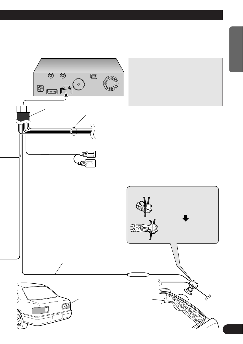
Purple/white (REVERSEGEAR SIGNAL INPUT)
This is connected so that the navigation system can
detect whether the car is moving forwards or backwards. Connect the purple/white lead to the lead
whose voltage changes when the shift lever is put
in reverse. Unless connected, the sensor may not
detect your car traveling forward/backward properly, and thus the position of your car detected by the
sensor may be misaligned from the actual position.
Note: When you use the ND-PG1 speed pulse generator (sold separately), please make sure to connect it.
Check the position of your car’s backup
lamp (the one that lights up when the
shift lever is in reverse [R]) and find the
backup lamp lead in the trunk.
Fuse resistor
Connection method
Clamp the backup lamp
lead.
Clamp firmly with
needle-nosed pliers.
Backup lamp lead.
ITALIANO NEDERLANDS
12
Connecting the System
This product
Yellow
To the terminal always supplied with power regardless of
ignition switch position.
Fuse holder (7.5 A)
Red
To the electric terminal controlled by the ignition switch
(12 V DC) ON/OFF.
Do not connect this lead to power source terminals to
which power is continuously supplied. If the lead is
connected to such terminals, the battery may be drained.
Orange/white
To lighting switch terminal.
Black
To car (metal) body. To keep electromagnetic noise from
the car body out of the navigation system, attach this lead
near the main unit.
Fuse resistor
Fuse resistor
Yellow/black, Purple/white, Pink, Lightgreen
Note: When replacing the fuse, be
sure to use only a fuse of the rating
prescribed on the fuse holder.
Power cord
See
pages 11-12.
Note: The yellow, red, and orange/white leads should
be connected to the opposite side of the fusebox
terminals from the battery.
☞
Connecting the power cord (2)
Note:
Cords for this product and those for other products
may be different colors even if they have the same
function. When connecting this product to another
product, refer to the supplied Installation manuals
of both products and connect cords that have the
same function.
13

Installation
CAUTION
• Certain state laws may prohibit or restrict the placement and use of this system in your car. Please comply with all applicable laws and regulations
regarding the use, installation, and operation of your navigation system.
• Pioneer does not recommend that you install or service your DVD navigation
unit yourself. Installing or servicing the product may expose you to risk of
electric shock or other hazards. Refer all installation and servicing of your
navigation unit to authorized Pioneer service personnel.
• Never install the unit in places where:
* It could injure the driver or passengers if the car stops suddenly.
* It may interfere with the driver’s operation of the car, such as on the floor
in front of the driver’s seat.
• Make sure there is nothing behind the dashboard or paneling when drilling
holes in them. Be careful not to damage fuel lines, brake lines or power
cables.
• When using screws, do not allow them to come into contact with any electrical lead. Vibration may damage wires, leading to a short circuit or other
damage to the car.
• To ensure proper installation, use the supplied parts in the manner specified.
If any parts other than the supplied ones are used, they may damage internal
parts of the unit or they may work loose and the unit may come off.
ENGLISH ESPAÑOL DEUTSCH FRANÇAIS
• It is extremely dangerous to allow the GPS antenna lead or microphone lead
to become wound around the steering column or shift lever. Be sure to install
the unit in such a way that it will not obstruct driving.
• Make sure that leads cannot get caught in a door or the sliding mechanism of
a seat, resulting in a short circuit.
• Please confirm the proper function of your car’s other equipment following
installation of the DVD navigation unit.
ITALIANO NEDERLANDS
14

Installation
To guard against electromagnetic interference
• In order to prevent interference, set the following items as far as possible from the main
unit of this Navigation System, other cables or leads:
- TV antenna and antenna lead
- FM, AM antenna and its lead
- GPS antenna and its lead
In addition you should lay each antenna lead as far as possible from other antenna leads.
Do not bind them together, lay them together, or cross them.
Such electromagnetic noise would increase the error for the location display.
Before installing and fixing
• Consult with your nearest dealer if installation requires the drilling of holes or other modifications of the car.
•Before finally installing the unit, connect the wiring temporarily, making sure it is all
connected up properly, and the unit and the system work properly.
• For the installation and attachment of the Connection box, consult the shop where you
bought the product, or your dealer.
Before using the adhesive tape
• Make sure the surface is free of moisture, dust, grime, oil, etc. before affixing the tape.
15
Installing the main unit
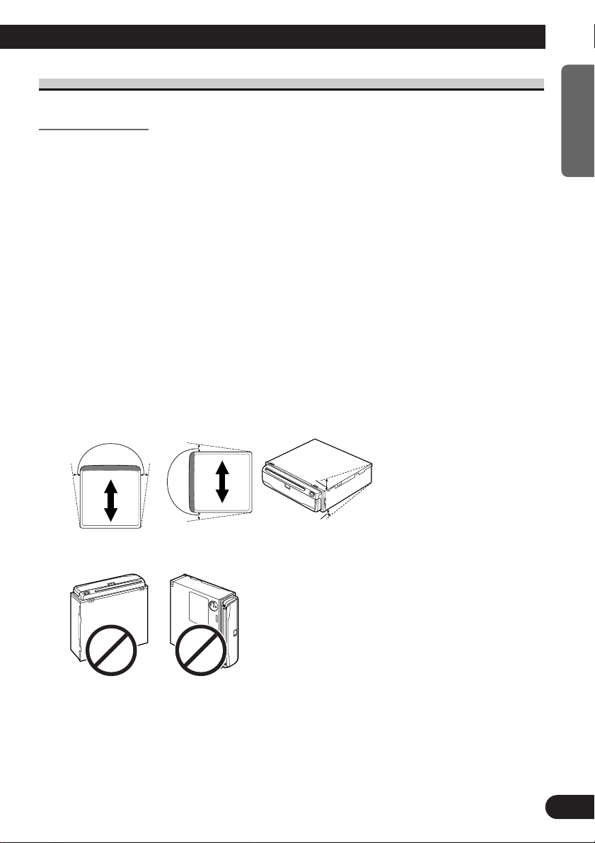
5°
5°
30°
15°
Installation notes
• Do not install the main unit in places where it may become subject to high temperatures
or humidity, such as:
* Places close to a heater outlet.
* Places exposed to direct sunlight, such as on top of the dashboard or the rear shelf.
* Places that may be splashed by rain, for example close to the door.
• The installation strength will depend on the car model and the installation position.
Choose a position where the main unit can be firmly installed, and install it securely.
If the main unit is not securely fastened, the errors in location display will be greater.
• Do not install the main unit on the board covering the spare tire or other places which
are subject to vibration.
• When the main unit is installed under a front seat, ensure that it does not obstruct the
sliding action of the seat.
• Do not install the main unit anywhere that cargo or the like will get on it. Strong
mechanical shock to the main unit would increase the errors in location display.
• Avoid installing the main unit in places where it will interfere with loading and unloading of the spare tire, jack, tools, etc.
• Check that a disc or a PC card can be ejected with the main unit installed.
• Install the main unit on a surface within +30 degrees to -15 degrees tolerance (within
five degrees to the left or right of your car’s direction of travel). A surface tilted more
than this would increase the errors in location display.
ENGLISH ESPAÑOL DEUTSCH FRANÇAIS
• Do not install the main unit vertically. Installing it this way can cause it to function
improperly.
ITALIANO NEDERLANDS
16
Installation
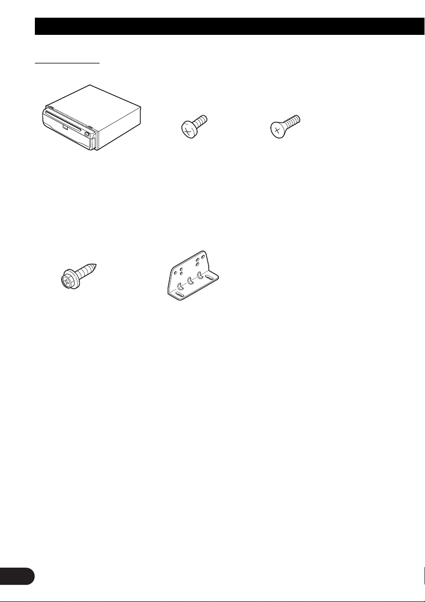
Parts supplied
Main unit
(6 × 16 mm)
(4 pcs.)
Binding screw
(5 × 6 mm)
Mounting angle (2 pcs.)Tapping screw
(4 pcs.)
Flush surface screw
(5 × 6 mm)
(4 pcs.)
17
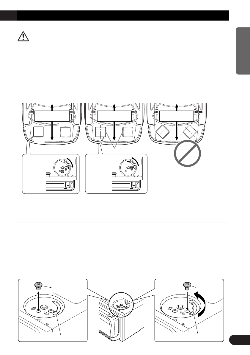
CAUTION
Locking screw
Installation direction lever
Underneath the DVD Navigation Unit
Locking screw
Installation direction lever
Front
Front Front
Front
Front
(Perpendicular)
Attachment
position of the
locking screw
↕
(Parallel)
Attachment
position of the
locking screw
↔
Forward / Backward
direction of car
Forward / Backward
direction of car
Forward / Backward
direction of car
• Install with the left and right sides of the DVD Navigation Unit perpendicular
or parallel to your car’s direction of travel. Do not install diagonally to your
car’s direction of travel or the current location will be displayed incorrectly.
• If you install the left and right sides of the DVD Navigation Unit parallel to
your car’s direction of travel, switch the installation direction lever, and
attach the locking screw to the “↔” side, or else the G sensor mounted in the
DVD Navigation Unit will not operate correctly.
ENGLISH ESPAÑOL DEUTSCH FRANÇAIS
If you install with the left and right sides of the DVD Navigation Unit parallel to
your car’s forward / backward direction
If you install with the left and right sides of the DVD Navigation Unit parallel to your car’s
forward / backward direction, remove the mounting screw underneath the DVD
Navigation Unit, and switch the installation direction lever. Then change the screw mounting position from “
sor mounted in the DVD Navigation Unit will not operate correctly.
1. Remove the locking screw attached to the installation direction lever.
2. Switch the lever, and attach the mounting screw to the “↔” side.
↔” side to “↕” side. If the screw is attached to the “↔” side, the G sen-
ITALIANO NEDERLANDS
18
Installation
Use the following holes on
the mounting angles.
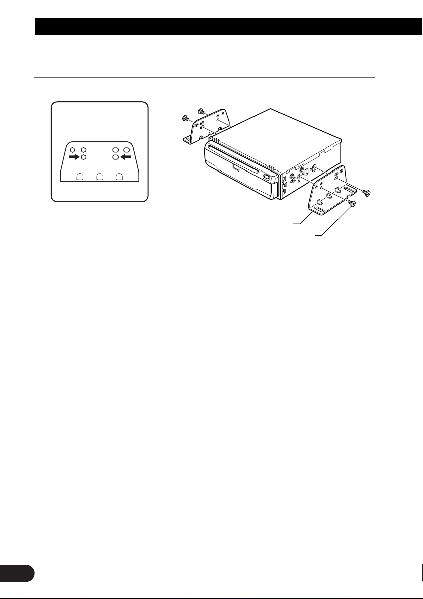
When installing the main unit inside the trunk, on the floor under a seat, etc.,
using tapping screws
1. Fit mounting angles to the sides of the main unit.
Mounting angle
Binding screw or flush surface screw
19
 Loading...