


Central Processing Unit
Before attempting to connect or operate this product,
please read these instructions carefully and save this manual for future use.
Model No. WJ-MPU850
CAUTION
RISK OF ELECTRIC SHOCK
DO NOT OPEN
CAUTION: TO REDUCE THE RISK OF ELECTRIC SHOCK,
DO NOT REMOVE COVER (OR BACK).
NO USER-SERVICEABLE PARTS INSIDE.
REFER SERVICING TO QUALIFIED SERVICE PERSONNEL.
|
The lightning flash with arrowhead sym- |
|
|
bol, within an equilateral triangle, is |
|
|
intended to alert the user to the pres- |
|
|
ence of uninsulated "dangerous voltage" |
|
|
within the product's enclosure that may |
|
SA 1965 |
be of sufficient magnitude to constitute a |
|
risk of electric shock to persons. |
||
|
The exclamation point within an equilateral triangle is intended to alert the user to the presence of important operating and maintenance (servicing) instructions in the literature accompanying the appliance.
SA 1966
For U.S.A
NOTE: This equipment has been tested and found to comply with the limits for a Class A digital device, pursuant to Part 15 of the FCC Rules. These limits are designed to provide reasonable protection against harmful interference when the equipment is operated in a commercial environment. This equipment generates, uses, and can radiate radio frequency energy and, if not installed and used in accordance with the instruction manual, may cause harmful interference to radio communications.
Operation of this equipment in a residential area is likely to cause harmful interference in which case the user will be required to correct the interference at his own expense.
FCC Caution: To assure continued compliance, (example - use only shielded interface cables when connecting to computer or peripheral devices). Any changes or modifications not expressly approved by the party responsible for compliance could void the user’s authority to operate this equipment.
The serial number of this product may be found on the rear of the unit.
You should note the serial number of this unit in the space provided and retain this book as a permanent record of your purchase to aid identification in the event of theft.
Model No.
Serial No.
WARNING:
To reduce the risk of fire or electric shock, do not expose this appliance to rain or moisture.
■ Preface
The WJ-MPU850 CPU is the Central Processing Unit for the System 850 Matrix Switcher. The System 850 Matrix Switcher is a CCTV surveillance system having multiple video inputs, multiple video outputs, and multiple control stations. The WJMPU850 is capable of controlling a maximum of 512 video input sources and a maximum of 64 video outputs, such as monitors, with 16 system controllers.
The WJ-MPU850 is a high-performance Intel X86 processor based computer running the OS-9 real time operating system allowing you to build up a redundant system of duplicate CPUs.
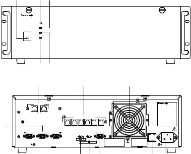
■ Appearance
● Front View
qw e
● Rear View
RESET
FAN ALARM
HDD
OPERATE
ACTIVE
Control Processing Unit WJ–MPU 850
|
t r |
|
|
|
|
|
|
|
|
|
|
y |
|
|
u |
|
|
|
|
!2 |
|
||
ETHERNET |
|
|
|
|
|
|
|
|
|
Central Processing Unit |
|
|
|
|
|
|
|
|
|
|
|
|
|
GYGTEM |
CAMERA |
|
|
|
|
|
|
|
|
|
|
CONTROLLER CROSS POINT |
|
|
|
|
|
|
|
|
|
|
|
|
OSD |
|
SYSYTEM |
|
(RS–485) |
|
|
|
|
||
|
|
|
|
|
|
|
|
||||
|
|
|
CONTROLLER |
|
|
|
|
|
|
||
i |
|
DATA 6 |
DATA 5 |
DATA 4 |
DATA 3 |
DATA 2 |
DATA 1 |
|
|
||
|
|
|
|
|
|
|
|
|
|
|
|
|
|
|
|
|
|
|
|
|
|
125V 3.0A |
AC IN |
PERIFERAL |
INTERFACE |
(RS–232C) |
REDUNDANT SATELLITE |
PARALLEL |
|
|
|||||
|
|
|
|
CPU |
|
MODE |
|
|
|
|
|
3 |
2 |
1 |
NO |
YES |
|
|
|
|
|
|
|
|
|
|
|
STANDALONE |
SATELLITE |
|
|
|
|||
|
|
|
|
|
|
|
|
|
|
SIGNAL |
|
|
|
|
|
|
|
|
|
|
|
GND |
|
|
|
|
o!0!1 |
!3!4 |
|||||||
qOperate Indicator (OPERATE)
Is on when the power of the WJ-MPU850 CPU is turned on.
Note: The power switch of the CPU is located underneath the front panel.
Remove the front panel by removing two screws on the panel.
wReset Button (RESET)
The RESET button is recessed inside the front panel hole to the right of the OPERATE indicator.
Press this button when the CPU rejects control from outboard equipment.
eFan Alarm Indicator (FAN ALARM)
Indicates the cooling fan status.
This LED lights when a temperature rise in the CPU is detected. Turn the power off and refer servicing to qualified service personnel.
rHDD (Hard Disk Drive) Indicator (HDD)
Indicates the hard disk drive status.
tActive Indicator (ACTIVE)
Indicates the system status of the CPU.
y Ethernet Ports (ETHERNET)
Exchange control data via Ethernet.
• SYSTEM CONTROLLER
This port is provided for controlling the 850 System with the WV-CU850 system controllers. Up to 16 controllers can be connected to this port through a hub.
Note: The total number of system controllers connected via RS-485 and Ethernet is limited to 16.
• CAMERA/CROSS POINT/OSD
This port is used to exchange control data between the cages through a hub.
uController Ports [SYSTEM CONTROLLER (RS485)]
These ports are provided for controlling the 850 System with the WV-CU350 system controllers. Up to 6 controllers can be connected
iPeripheral Interface Ports [PERIPHERAL INTERFACE (RS-232C)]
These ports are reserved for future use or factory tests.
oRedundant CPU selector (REDUNDANT CPU)
Selects either a redundant system or a standalone system.
The factory default setting is NO.
!0Mode Selector (SATELLITE MODE)
Always keep in STANDALONE position.
!1Parallel Port (PARALLEL)
This port is used to connect to the WJ-MPS855 CPU Switch Unit for a redundant system.
!2Cooling Fan Unit
Prevents the temperature of the CPU from rising. Do not block the ventilation opening on the cover.
!3Fuse Holder
!4AC Inlet Socket (AC IN)
Plug the power cord (supplied as a standard accessory) into this socket and connect it to an AC outlet.
-2-
 Loading...