


Panasonic WJHD716-8000T2, WJHD716-3000T3, WJHD716-4000T2, WJHD716-26000T2, WJHD716-2000T2 User Manual
...Installation Guide
Digital Disk Recorder
Model No. WJ-HD616K
WJ-HD716K
ERROR |
ALARM |
|
ALARM |
|
|
RESET |
|
ALARM |
STS |
|
|
SUSPEND |
HDD1 |
A/F |
|
|
|
||
TIMER |
|
|
|
|
|
HDD2 |
|
OPERATE |
|
HDD3 |
|
|
|
|
|
|
|
HDD4 |
|
MONITOR
SEQ
OSD MULTI SCREEN
 1
1 
 5
5 
 9
9  13
13
 2
2 

 6
6  0/10
0/10  14
14
3 |
4 |
|
|
7 |
8 |
|
|
11 |
12 |
|
|
15 |
16 |
|
STOP |
PLAY |
PAUSE |
|
|
|
REC |
REC STOP |
||
|
|
|
||
GOTO LAST |
GOTO DATE |
SEARCH |
|
|
|
|
COPY |
||
|
|
|
||
|
|
|
|
|
SUB |
|
|
SETUP ESC |
|
|
|
|
|
|
MENU |
|
|
|
|
|
|
|
SET |
|


 Digital Disk Recorder WJ-HD616
MOUSE
This illustration represents WJ-HD616K.
Before attempting to connect or operate this product,
please read these instructions carefully and save this manual for future use.
No model number suffix is shown in this manual.
WARNING:
•This apparatus must be earthed.
•Apparatus shall be connected to a main socket outlet with a protective earthing connection.
•The mains plug or an appliance coupler shall remain readily operable.
•To prevent fire or electric shock hazard, do not expose this apparatus to rain or moisture.
•The apparatus should not be exposed to dripping or splashing and that no objects filled with liquids, such as vases, should be placed on the apparatus.
•All work related to the installation of this product should be made by qualified service personnel or system installers.
•The connections should comply with local electrical code.
CAUTION:
Before attempting to connect or operate this product, please read the label on the bottom.
CAUTION:
An ALL-POLE MAINS SWITCH with a contact separation of at least 3 mm in each pole shall be incorporated in the electrical installation of the building.
CAUTION
RISK OF ELECTRIC SHOCK
DO NOT OPEN
CAUTION: TO REDUCE THE RISK OF ELECTRIC SHOCK,
DO NOT REMOVE COVER (OR BACK).
NO USER-SERVICEABLE PARTS INSIDE.
REFER SERVICING TO QUALIFIED SERVICE PERSONNEL.
The lightning flash with arrowhead symbol, within an equilateral triangle, is intended to alert the user to the presence of uninsulated "dangerous voltage" within the product's enclosure that may be of sufficient magnitude to constitute a risk of electric shock to persons.
The exclamation point within an equilateral triangle is intended to alert the user to the presence of important operating and maintenance (servicing) instructions in the literature accompanying the appliance.
Power disconnection. Unit with or without ON-OFF switches have power supplied to the unit whenever the power cord is inserted into the power source; however, the unit is operational only when the ON-OFF switch is in the ON position. Unplug the power cord to disconnect the main power for all units.
For Canada
This Class A digital apparatus complies with Canadian ICES-003.
For U.S.A.
NOTE: This equipment has been tested and found to comply with the limits for a Class A digital device, pursuant to Part 15 of the FCC Rules. These limits are designed to provide reasonable protection against harmful interference when the equipment is operated in a commercial environment. This equipment generates, uses, and can radiate radio frequency energy and, if not installed and used in accordance with the instruction manual, may cause harmful interference to radio communications.
Operation of this equipment in a residential area is likely to cause harmful interference in which case the user will be required to correct the interference at his own expense.
FCC Caution: To assure continued compliance, (example - use only shielded interface cables when connecting to computer or peripheral devices). Any changes or modifications not expressly approved by the party responsible for compliance could void the user’s authority to operate this equipment.
For U.S.A.
The model number and serial number of this product may be found on the surface of the unit.
You should note the model number and serial number of this unit in the space provided and retain this book as a permanent record of your purchase to aid identification in the event of theft.
Model No.
Serial No.
2

Limitation of liability
THIS PUBLICATION IS PROVIDED "AS IS" WITHOUT WARRANTY OF ANY KIND, EITHER EXPRESS OR IMPLIED, INCLUDING BUT NOT LIMITED TO, THE IMPLIED WARRANTIES OF MERCHANTABILITY, FITNESS FOR ANY PARTICULAR PURPOSE, OR NON-INFRINGEMENT OF THE THIRD PARTY'S RIGHT.
THIS PUBLICATION COULD INCLUDE TECHNICAL INACCURACIES OR TYPOGRAPHICAL ERRORS. CHANGES ARE ADDED TO THE INFORMATION HEREIN, AT ANY TIME, FOR THE IMPROVEMENTS OF THIS PUBLICATION AND/OR THE CORRESPONDING PRODUCT
(S).
Disclaimer of warranty
IN NO EVENT SHALL Panasonic Corporation BE LIABLE TO ANY PARTY OR ANY PERSON, EXCEPT FOR REPLACEMENT OR REASONABLE MAINTENANCE OF THE PRODUCT, FOR THE CASES, INCLUDING BUT NOT LIMITED TO BELOW:
(1)ANY DAMAGE AND LOSS, INCLUDING WITHOUT LIMITATION, DIRECT OR INDIRECT, SPECIAL, CONSEQUENTIAL OR EXEMPLARY, ARISING OUT OF OR RELATING TO THE PRODUCT;
(2)PERSONAL INJURY OR ANY DAMAGE CAUSED BY INAPPROPRIATE USE OR NEGLIGENT OPERATION OF THE USER;
(3)UNAUTHORIZED DISASSEMBLE, REPAIR OR MODIFICATION OF THE PRODUCT BY THE USER;
(4)INCONVENIENCE OR ANY LOSS ARISING WHEN IMAGES ARE NOT DISPLAYED, DUE TO ANY REASON OR CAUSE INCLUDING ANY FAILURE OR PROBLEM OF THE PRODUCT;
(5)ANY PROBLEM, CONSEQUENTIAL INCONVENIENCE, OR LOSS OR DAMAGE, ARISING OUT OF THE SYSTEM COMBINED BY THE DEVICES OF THIRD PARTY;
(6)ANY CLAIM OR ACTION FOR DAMAGES, BROUGHT BY ANY PERSON OR ORGANIZATION BEING A PHOTOGENIC SUBJECT, DUE TO VIOLATION OF PRIVACY WITH THE RESULT OF THAT SURVEILLANCE-CAMERA'S PICTURE, INCLUDING SAVED DATA, FOR SOME REASON, BECOMES PUBLIC OR IS USED FOR THE PURPOSE OTHER THAN SURVEILLANCE;
(7)LOSS OF REGISTERED DATA CAUSED BY ANY FAILURE.
3

Important safety instructions
1)Read these instructions.
2)Keep these instructions.
3)Heed all warnings.
4)Follow all instructions.
5)Do not use this apparatus near water.
6)Clean only with dry cloth.
7)Do not block any ventilation openings. Install in accordance with the manufacturer's instructions.
8)Do not install near any heat sources such as radiators, heat registers, stoves, or other apparatus (including amplifiers) that produce heat.
9)Do not defeat the safety purpose of the polarized or grounding-type plug. A polarized plug has two blades with one wider than the other. A grounding type plug has two blades and a third grounding prong. The wide blade or the third prong are provided for your safety. If the provided plug does not fit into your outlet, consult an electrician for replacement of the obsolete outlet.
10)Protect the power cord from being walked on or pinched particularly at plugs, convenience receptacles, and the point where they exit from the apparatus.
11)Only use attachments/accessories specified by the manufacturer.
12)Use only with the cart, stand, tripod, bracket, or table specified by the manufacturer, or sold with the apparatus. When a cart is used, use caution when moving the cart/apparatus combination to avoid injury from tip-over.
S3125A
13)Unplug this apparatus during lightning storms or when unused for long periods of time.
14)Refer all servicing to qualified service personnel. Servicing is required when the apparatus has been damaged in any way, such as power-supply cord or plug is damaged, liquid has been spilled or objects have fallen into the apparatus, the apparatus has been exposed to rain or moisture, does not operate normally, or has been dropped.
4

Contents
Limitation of liability....................................................... |
3 |
Disclaimer of warranty................................................... |
3 |
Important safety instructions......................................... |
4 |
Preface........................................................................... |
7 |
Features......................................................................... |
7 |
System configuration..................................................... |
8 |
About the user manuals................................................. |
9 |
System requirements for a PC....................................... |
9 |
Trademarks and registered trademarks....................... |
10 |
Copyright..................................................................... |
10 |
Abbreviations............................................................... |
10 |
Network security.......................................................... |
11 |
Precautions.................................................................. |
12 |
Precautions for Installation.......................................... |
14 |
Major operating controls and their functions............... |
16 |
■ Front view............................................................... |
16 |
■ Rear view............................................................... |
22 |
User/Host management............................................... |
24 |
Basic operation............................................................ |
26 |
Operations using the buttons on the front cover....... |
26 |
Operations using a mouse......................................... |
26 |
Operations flow............................................................ |
27 |
Rack mounting............................................................. |
28 |
Connections................................................................. |
29 |
Connection of cameras.............................................. |
29 |
Connection of monitors............................................. |
30 |
Connection of a PC.................................................... |
32 |
Connection of an extension unit................................ |
33 |
Connection of a VCR................................................. |
34 |
Connection of a PS·Data compatible device............. |
35 |
Cascading connection of multiple recorders............. |
37 |
Connection of RS485 cameras.................................. |
42 |
About the connectors.................................................. |
44 |
How to use the terminals of the ALARM/CONTROL |
|
connector................................................................... |
44 |
How to use the terminals of the ALARM connector..48 |
|
Time and polarities of the ALARM/CONTROL terminal |
|
and the ALARM terminal............................................ |
50 |
Mode switch.............................................................. |
51 |
RS485 port................................................................. |
51 |
Install/remove HDD units............................................. |
52 |
Install the HDD units.................................................. |
52 |
Remove the HDD unit................................................ |
53 |
Determine the operational mode of the hard disk |
|
drives............................................................................ |
54 |
Startup......................................................................... |
55 |
Turn on the power...................................................... |
55 |
Turn off the power...................................................... |
55 |
Configure the minimum settings required to use the |
|
recorder........................................................................ |
56 |
Setup menu.................................................................. |
57 |
About Setup menu..................................................... |
58 |
How to operate the setup menu................................ |
59 |
About the operation of on-screen keyboard |
|
(for character entry).................................................... |
62 |
Configure the minimum settings required to |
|
operate the recorder [Quick]........................................ |
63 |
Configure the basic settings of the recorder [Basic].... |
65 |
Configure the settings relating to the basic operation |
|
of recorder [Basic]...................................................... |
65 |
Configure the settings relating to time & date |
|
[Time & date].............................................................. |
66 |
Basic settings for recording [Recording].................... |
68 |
Configure the settings relating to audio [Audio]......... |
69 |
Settings for emergency recording |
|
[Emergency rec.]........................................................ |
70 |
Configure the settings relating to event [Event]........... |
71 |
Configure the common settings for event actions |
|
[Common].................................................................. |
71 |
Configure the event action at a terminal alarm |
|
occurrence [Terminal/Command]............................... |
72 |
Configure the event action at a camera site alarm |
|
occurrence [Site alarm].............................................. |
73 |
Configure the event action at a video loss |
|
occurrence [Video loss].............................................. |
74 |
Configure the event action at a VMD occurrence |
|
[VMD]......................................................................... |
75 |
Configure the settings relating to recording/event |
|
schedules [Schedule]................................................... |
79 |
Flowchart on how to create a schedule..................... |
79 |
Create a program [Program]...................................... |
79 |
Assign a program after setting the time zone |
|
[Time table]................................................................ |
81 |
Configure the settings of recording programs for |
|
special days [Special days]........................................ |
82 |
Configure the settings relating to display [Display]...... |
83 |
Common settings for monitors [Common]................ |
83 |
Configure the display settings for Monitor 1 |
|
[Monitor 1].................................................................. |
86 |
Configure the display settings for Monitor 2 |
|
[Monitor 2].................................................................. |
88 |
Configure the camera title [Camera title]................... |
89 |
Configure the settings relating to the sequential |
|
display on a PC monitor [Network]............................ |
90 |
Configure the settings relating to the cascade |
|
connection [Cascade]................................................ |
91 |
Configure the settings relating to communication |
|
with other devices [Communication]............................ |
92 |
Configure the communication settings for camera |
|
control [Camera control]............................................ |
92 |
Configure the settings relating to PS·Data |
|
[PS·Data setup].......................................................... |
93 |
Configure the settings relating to RS485 |
|
[RS485 setup]............................................................ |
94 |
Configure the settings relating to the server |
|
[Server]......................................................................... |
95 |
Configure the settings relating to time adjustment |
|
according to the NTP server [NTP]............................ |
95 |
Configure the settings relating to the FTP server |
|
[FTP]........................................................................... |
96 |
Configure the settings relating to the mail |
|
notification [Mail]........................................................ |
97 |
Configure the settings relating to network |
|
[Network]...................................................................... |
99 |
Configure the basic settings relating to a network |
|
[Basic]........................................................................ |
99 |
Configure the settings relating to DNS [DNS].......... |
101 |
Configure the settings relating to DDNS [DDNS]..... |
102 |
Configure the settings relating to SNMP [SNMP].... |
103 |
Configure the Panasonic alarm protocol settings |
|
[Panasonic alarm protocol]...................................... |
104 |
Configure the settings relating to network |
|
transmission [Transmission]..................................... |
105 |
Configure the settings relating to the user |
|
management [User mng.]........................................... |
106 |
5

Configure the basic settings relating to user |
|
management [Basic]................................................ |
106 |
Register or change the administrator information |
|
[Administrator].......................................................... |
107 |
Register, change or delete the user information |
|
[User]........................................................................ |
108 |
Register, change, or delete a PC (host) accessible |
|
to this recorder [Host].............................................. |
110 |
Setting of operation level [User level]...................... |
112 |
Configure the settings relating to SD5 camera |
|
[SD5Link].................................................................... |
113 |
Configure the settings relating to the i-VMD |
|
function of SD5 camera [i-VMD setup].................... |
113 |
Uploading or downloading the settings of SD5Link |
|
cameras [Setup data]............................................... |
118 |
Configure the settings relating to maintenance |
|
[Maintenance]............................................................. |
119 |
Check the product information such as the version |
|
[Product information]............................................... |
119 |
Confirm the available hard disk space |
|
[Disk information]..................................................... |
119 |
Confirm the network information [Network |
|
information].............................................................. |
121 |
Configure the settings and operations relating |
|
to hard disk drives [Disk].......................................... |
122 |
Manage the settings [Settings management].......... |
123 |
View Log Information [Logs].................................... |
124 |
Manage hard disk drives............................................ |
126 |
About hard disk drives............................................. |
126 |
About the RAID 5/RAID 6 mode.............................. |
126 |
Determine the operation mode................................ |
126 |
About the disk configuration page........................... |
127 |
Replacement/addition of hard disk drives................. |
133 |
Replace hard disk drives......................................... |
133 |
Shutdown process of the hard disk drives.............. |
133 |
Add a hard disk drive............................................... |
135 |
Auto recognition of hard disk drives........................ |
136 |
Operation of the extension unit.................................. |
138 |
Add an extension unit to the system....................... |
138 |
Shutdown process of the extension unit................. |
139 |
About the error log..................................................... |
140 |
Error recovery of the hard disk drive (when |
|
operating in the RAID mode)...................................... |
145 |
Replacement of a faulty hard disk drive in the |
|
RAID mode............................................................... |
146 |
Troubleshooting......................................................... |
147 |
Check the power cord, connector and plug |
|
periodically............................................................... |
152 |
Specifications............................................................. |
153 |
Standard accessories................................................ |
154 |
Optional Accessories................................................. |
154 |
6

Preface
The digital disk recorders WJ-HD616K, WJ-HD716K are designed for use within a surveillance system, and record images from up to 16 cameras on the hard disk drives.
This product supports HDMI (High-Definition Multimedia Interface) standard which allows displaying playback/live images with superior quality when connecting to a high-definition monitor using an optional HDMI cable.
It is possible to operate cameras from this product to display images from multiple cameras or switch cameras from which images are to be displayed, etc.
* No hard disk drive is supplied with this recorder. For purchasing the hard disk drive, contact your dealer.
Features
Easy operation using a PC mouse
It is possible to operate this product while monitoring a screen when directly connecting a PC mouse (commercially available) to
this product.
Image display on a High-definition monitor
It is possible to display recorded images or live images from cameras on a high-definition monitor (1 920 x 1 080).
Easy hard disk drive replacement
It is possible to install/remove hard disk drives easily into/from the recorder by opening the front cover to access the HDD slots. When 2 or more hard disk drives are installed, it is possible to replace the hard disk drives without stopping the current recording. Locally procured hard disk drives are to be encased in optional HDD canisters (WJ-HDU40K). At the time of shipment from the factory, 4 canisters have been already installed in the recorder. Contact your dealer for purchasing additional HDD canisters and hard disk drives.
HDD fault-tolerance system using the RAID function
The RAID function is available as the HDD fault-tolerance system when the optional RAID board (WJ-HD601) is installed.
In addition to the RAID 5 mode that recovers data when a single hard disk drive becomes faulty, there is RAID 6 mode that can recover data even if 2 hard disk drives become faulty. Operation in the RAID mode is one of the solutions as the HDD fault-toler- ance system that prevents data loss when handling a large amount of data on a large amount of storage.
Coordination with SD5 cameras
The following functions are available when connecting to Panasonic SD5 cameras using coaxial cables. Refer to the operating instructions of the camera for further information about SD5 cameras.
•Alarm recording/Search and play
When the camera issued an alarm (arisen by detection of an intruder or appearance/disappearance of object), the alarm recording will start.
Images recorded by the alarm recording can be searched and played by designating search conditions such as the alarm type.
•i-VMD area setting
The settings of the VMD areas created from the camera and the setting of the depth compensation configured from the camera can be edited on the recorder motion detection will become more sensitive using the depth compensation. Refer to the operating instructions of cameras for further information about the i-VMD function.
•Save and load of the setup data of the camera
The settings of the camera (setup data) can be saved on the recorder and the saved setup data can be loaded to the camera.
It is convenient when a camera goes out of order and required to be exchanged since a new camera can be used with the same settings as it was.
7

SDHC/SD memory card slot
Images being captured at an alarm occurrence or at a network error can be saved on a SDHC/SD memory card (option) automatically.
It is also possible to directly save images on a SDHC/SD memory card. Images saved on the SDHC/SD memory card can be played or downloaded using a web browser.
Note:
•Compatible SDHC/SD memory card (option) manufactured by Panasonic
SDHC memory card: 4 GB, 8 GB, 16 GB, 32 GB
SD memory card: |
256 MB, 512 MB, 1GB, 2GB |
|
(miniSD card and micro SD card excluded) |
|
|
System configuration
Microphone x4 |
Monitor 1 |
Monitor 2 |
|
System camera or combination camera x16
Amplifier
|
|
|
ALARM |
|
|
|
|
STOP |
PLAY |
PAUSE |
REC REC STOP |
|
|
|
ERROR |
ALARM |
|
RESET |
MONITOR |
|
|
|
REV |
FWD |
|
||||
|
|
1 |
2 |
3 |
4 |
|
|
|
|
|||||
|
|
|
|
|
|
|
|
|
|
|
||||
ALARM |
STS |
HDD 1 |
A/F |
SEQ |
|
|
|
GOTO LAST |
GOTO DATE |
SEARCH |
COPY |
|
|
|
SUSPEND |
5 |
6 |
7 |
8 |
|
|
|
|
|
|
||||
|
|
|
|
|
|
|
|
|
|
|
||||
TIMER |
|
HDD 2 |
|
OSD |
|
|
|
|
|
|
|
|
|
|
|
|
|
|
9 |
0/10 |
11 |
12 |
|
|
SETUP /ESC |
|
|
|
|
|
|
HDD 3 |
|
|
|
|
|
|
|
|
||||
|
|
|
|
|
|
|
|
SUB |
|
|
|
|
|
|
OPERATE |
|
HDD 4 |
|
MULTI SCREEN |
|
|
|
MENU |
|
|
SET |
HOLD |
|
|
|
|
|
13 |
14 |
15 |
16 |
|
|
|
|
|
|
||
|
|
|
|
|
|
|
|
|
|
|
||||
|
|
|
|
|
|
|
|
|
|
|
|
Digital Disk Recorder WJ-HD616 |
MOUSE |
|
Powered
speaker
Extension unit x3 |
System controller |
Network
PC
8

About the user manuals
The following 3 manuals are provided for the WJ-HD616K / WJ-HD716K.
Installation Guide (this document): |
Contains descriptions of how to install/connect this product and how to configure |
|
the required settings. |
Operating Instructions (PDF): |
Contains descriptions of how to operate this product. |
|
(Both operations using the interface on the product and using a PC via a network are |
|
provided) |
Quick Reference Guide: |
Contains descriptions of how to configure the basic settings and to operate functions |
|
frequently used. |
Adobe® Reader® is required to read the PDF files on the provided CD-ROM. When Adobe® Reader® is not installed on the PC, download the latest Adobe® Reader® from the Adobe web site and install it.
This product is described as "HD616K" or "HD716K" in the manuals and on the setup menus.
Refer to "readme.txt" on the provided CD-ROM for further information about the optional dedicated software, compatible cameras and their versions.
A DVD drive (WJ-HDB611) and RAID board (WJ-HDB601) are optional.
When these optional products are installed, the following functions will become avaialable.
• Built-in DVD drive: Copying of recorded images and audio onto a DVD disc
Playback of recorded images and audio copied on a DVD
• RAID board: Switching of the operational mode to RAID 5 or RAID 6 and running system with RAID 5 or
RAID 6
In these operating instructions, instructions are provided on the assumption that both the optional DVD drive and RAID board are installed.
System requirements for a PC
It is recommended to operate this unit using a PC that meets the following system requirements.
OS: |
Microsoft® Windows Vista® Business SP1 (32-bit) |
|
Microsoft® Windows® XP Professional SP3 |
|
Microsoft® Windows® XP Home Edition SP3 |
OS language: |
English, French, Spanish, German, Italian, Russian |
CPU: |
Intel® Core™2 Duo 2.66 GHz or faster |
Memory: |
1 GB or more (512 MB or more when using Windows® XP) |
Monitor: |
1 024 x 768 pixels or more, 24-bit True color or better |
Network interface: |
10/100 Mbps Network interface card must be installed |
Web browser: |
Windows® Internet Explorer® 7.0* |
|
Microsoft® Internet Explorer® 6.0 SP3 |
Audio: |
Sound card (When using the audio function) |
Other: |
CD-ROM drive: It is necessary to refer to the operating instructions on the provided CD-ROM. |
|
DirectX® 9.0c or later |
|
Adobe® Reader®: It is necessary to refer to the operating instructions on the provided CD-ROM. |
* When using Microsoft® Windows® Vista®
Important:
•If using a PC that does not meet the above system requirements, it may cause problems such as slow imaging or the web browser becomes inoperable.
•Audio will not be heard if a sound card is not installed on a PC.
•Microsoft® Windows® XP Professional x64 Edition is not supported.
Note:
•Refer to "Notes on Windows Vista®" (PDF) on the provided CD-ROM for further information about system requirements for a PC and precautions when using Microsoft® Windows Vista®.
9

Trademarks and registered trademarks
Adobe, Adobe logo and Reader are either registered trademarks or trademarks of Adobe Systems Incorporated in the United States and/or other countries.
Microsoft, Windows, Windows Vista, Internet Explorer, ActiveX and DirectX are either registered trademarks or trademarks of Microsoft Corporation in the United States and other countries.
Intel and Intel Core are trademarks or registered trademarks of Intel Corporation or its subsidiaries in the United States and other countries.
HDMI, the HDMI logo and High-Definition Multimedia Interface are trademarks or registered trademarks of HDMI Licensing LLC. SDHC logo is a trademark of the SD Card Association.
Other names of companies and products contained in these operating instructions may be trademarks or registered trademarks of their respective owners.
Copyright
Distributing, copying, disassembling, reverse compiling, reverse engineering, and also exporting in violation of export laws of the software provided with this product, are all expressly prohibited.
This product incorporates copy protection technology that is protected by U.S. and foreign patents, including patent numbers 5,315,448 and 6,836,549, and other intellectual property rights. The use of Macrovision's copy protection technology in the product must be authorized by Macrovision.
Reverse engineering or disassembly is prohibited.
Abbreviations
The following abbreviations are used in this manual.
Microsoft® Windows Vista® Business SP1 (32-bit) is described as Windows Vista.
Microsoft® Windows® XP Professional SP3 and Microsoft® Windows® XP Home Edition SP3 are described as Windows XP. Windows® Internet Explorer® 7.0 and Microsoft® Internet Explorer® 6.0 SP3 are described as Internet Explorer.
SDHC memory card and SD memory card are described as SDHC/SD memory card.
10
Network security
As you will use this product connected to a network, your attention is called to the following security risks. q Leakage or theft of information through this product
w Use of this product for illegal operations by persons with malicious intent
e Interference with or stoppage of this product by persons with malicious intent
It is your responsibility to take precautions such as those described below to protect yourself against the above network security risks.
•Use this product in a network secured by a firewall, etc.
•If this product is connected to a network that includes PCs, make sure that the system is not infected by computer viruses or other malicious entities (using a regularly updated anti-virus program, anti-spyware program, etc.).
•Protect your network against unauthorized access by restricting users to those who log in with an authorized user name and password.
•Apply measures such as user authentication for the servers and the connected devices to protect your network against leakage or theft of information, including image data, authentication information (user names and passwords), alarm mail information, FTP server information, etc.
11

Precautions
Power source
The input power source for this product is 120 V AC, 60 Hz. Do not connect to the outlet that provides the power to equipments that requires a measurable amount of power (such as a copy machine, air conditioner, etc.). Avoid placing this product in locations where is subject to water.
Ambient operating temperature
Use this product at temperatures between +5 °C to +45 °C {+41 °F to +113 °F}. Failure to do so may damage the internal parts or cause malfunction. Performance and lifetime of hard disk drives are easily affected by heat (used at high temperature). It is recommended to use this product at temperatures between +20 °C to +30 °C {+68 °F to +86 °F}.
POWER switch
The POWER switch is located on the rear of this product. Even though the POWER switch is set to "OFF", the power supply will not be cut. To cut the power supply, unplug the power plug of this product from the AC outlet. When using the power supply control unit, turn off the power of the power supply control unit.
IN |
|
|
CASCADE |
|
|
OUT |
|
|
TO |
|
|
2 |
1 |
POWER |
|
|
ON |
|
1 |
OFF |
|
OUT |
|
|
|
|
2 |
|
|
|
AC IN |
SIGNAL |
|
|
GND |
POWER switch
Built-in backup battery
•Before the first use, charge the built-in backup battery
(lithium battery) by turning on the power for 48 hours or more. If it is not charged enough, in a case where the power goes down, the internal clock may keep bad time or the operative condition may be different to that before the electric power failure.
•The built-in battery life is approx. 5 years as an indication of replacement. (The built-in battery life may become shorter depending on the use condition.)Replace the built-in battery after 5 years of use. ("5 years of use" is just an indication of replacement. We are not providing any guarantee of the built-in battery lifetime.)When the built-in battery life runs out, some settings such as the time and date setting will not be saved once the power is turned off.
•Ask your dealer when replacement of the battery is required.
Hard disk drive (HDD)
•Hard disk drives are vulnerable to vibration. Handle them with care.
It is possible to damage them if they are moved while their motors are still running.
•Do not move them just after turning the power off (for around 30 seconds).
•The lifetime of hard disk drives is limited by use. Write errors may occur frequently after around 20 000 hours of operation, and the head and motor deterioration may occur after around 30 000 hours of operation. They will reach the end of their lifetime after 30 000 hours of operation if they have been used at the recommended ambient temperature (approx. +25 °C {+77 °F})
•It is recommended to replace them after around
18 000 hours of operation to prevent data loss from disk failures.
•When hard disk drive trouble occurs, replace it immediately.
Contact your dealer about servicing.
SDHC/SD memory card
•When using an unformatted SDHC/SD memory card, format it using this product. Data on a SDHC/SD memory card will be deleted when it is formatted. When using an unformatted SDHC/SD memory card or a SDHC/SD memory card formatted using a device other than this product, it may not work correctly or performance of this product may be deteriorated. Refer to Operating Instructions (PDF) for how to format a SDHC/SD memory card.
•When using a SDHC/SD memory card, it is recommended to use one manufactured by Panasonic. Please be forewarned that any loss of information, such as images, on a SDHC/SD memory card is not guaranteed under any circumstances if a SDHC/SD memory card of other manufacturer's. (+ Page 8)
•Refer to page 18 for how to insert/remove a SDHC/SD memory card.
Prevent condensation from forming
If this happens, it can cause malfunction.
Leave it switched off for around 2 hours in the following cases.
•When this product is placed in an extremely humid place.
•When this product is placed in a room where a heater has just been turned on.
•When this product is moved from an air-conditioned room to a humid and high-temperature room.
When this product is not supposed to be used for a certain period
Turn on the power (approx. once a week), and perform recording/playback to prevent interferences with functions.
12

Cleaning
•Turn the power off, and then use a soft cloth to clean this product. When the dirt is hard to remove, use a mild detergent and wipe gently. Wipe out the detergent completely using a soft cloth.
•Do not use strong or abrasive detergents when cleaning the body.
•When using a chemical cloth for cleaning, read the caution provided with the chemical cloth product.
Indication label
Refer to the indication label placed on the surface of this product as to the indications of equipment classification and power source, etc.
AVC patent portfolio license
This product is licensed under the AVC Patent Portfolio License for the personal and non-commercial use of a consumer to (i) Encode video in compliance with the AVC Standard ("AVC video") and/or (ii) Decode AVC video that was encoded by a consumer engaged in a personal and non-commercial activity and/or was obtained from a video provider licensed to provide AVC video. No license is granted or shall be implied for any other use. Additional information may be obtained from MPEG LA, L.L.C.
See http://www.mpegla.com.
GPL/LGPL
•This product contains software licensed under GPL
(GNU General Public License), LGPL (GNU Lesser General Public License), etc.
•Customers can duplicate, distribute and modify the source code of the software under license of GPL and/or LGPL.
•Read the "readme.txt" the provided CD-ROM for further information about the software.
•Please note that Panasonic shall not respond to any inquiries regarding the source code.
Handle this product with care.
Do not strike or shake, as this may damage this product.
Do not strike or give a strong shock to this product.
It may cause damage or allow water to enter this product.
13
Precautions for Installation
This product is designed for indoor use.
Avoid the following locations for installation.
•Locations exposed to direct sunlight
•Places subject to having strong vibration or impact
•Near magnetic field sources such as a television or speakers
•Place where condensation forms easily, where temperature changes greatly, humid places
•Steamy and oily places such as kitchens
•Places which are not level
•Places subject to dust
•Places subject to water splash or spray
Do not install this product in locations where the product or the cables can be destroyed or damaged by persons with malicious intent.
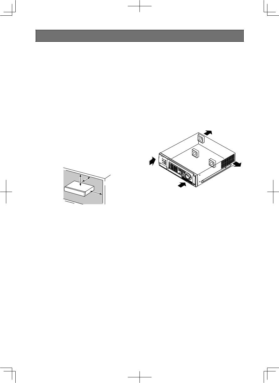
Place this product horizontally on a level surface.
Do not place this product in an upright position. When stacking multiple recorders, clear a space of more than 5 cm {1-31/32"} from both sides, the top, the bottom and the rear of them.
More than 5 cm {1-31/32"}
More than
5 cm {1-31/32"}
More than
5 cm {1-31/32"}
Heat dissipation
Refer to the following to prevent fire and malfunction of this product.
•Do not block the ventilation openings in the cover to prevent this product from overheating. Maintain this product periodically to prevent dust from blocking openings.
•A lifetime of cooling fans is limited by use. It is recommended to replace them after approx. 30 000 hours of operation. Contact your dealer for replacement of the cooling fans.
•Clear a space of more than 5 cm from both sides, the top and the rear of this product. Do not block the ventilation openings on the front cover since this product is designed to cool the hard disk drives by inhaling air from the front.
Avoid placing the unit near noise sources
If the cables are placed near noise sources such as fluorescent lamps, noises may be produced. In this case, rewire avoiding the noise sources, or move this product to a place far from the source.
Power source
A grounding connection must be made before connecting the power plug of this product to the main power supply. When disconnecting the grounding wire, make sure that the power plug of this product is disconnected from the main power supply.
How to mount the power cord
Be sure to connect the power cord via any of the following breaking devices:
•Connect the power cord via a power supply control unit.
•Install the product near a power outlet, and connect the power cord via the power plug.
•Connect the power cord to the breaker with contact gap of 3.0 mm or more of a distribution board. The breaker shall be able to shut down all the poles of the main power supply except the ground protective conductor.
14
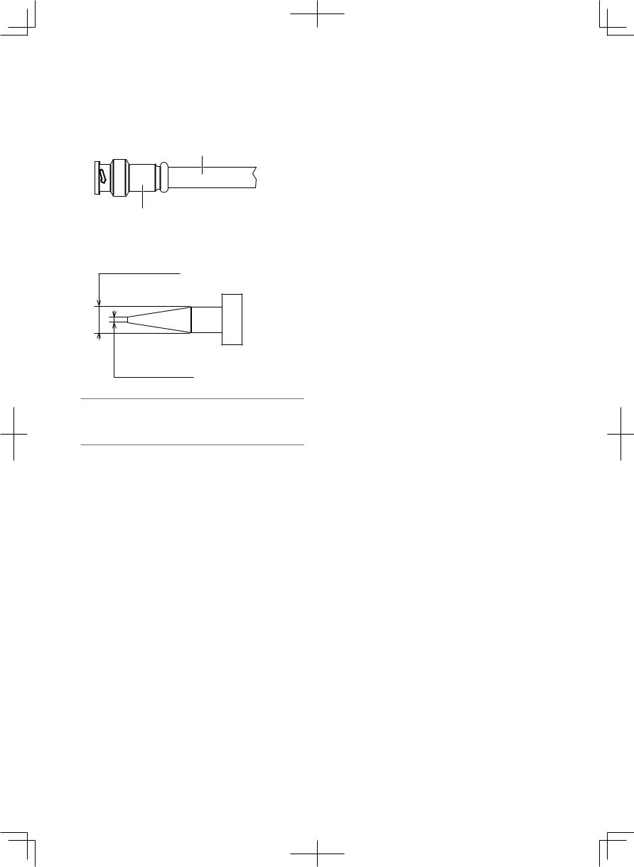
For BNC cable connection
Use only the recommended plug below when connecting the BNC plug to the connectors on the rear panel of the recorder.
Applicable plug: MIL-C39012C or MIL-C39012/16F
* Suffixes attached to the standards may be updated.
BNC cable (locally procured)
Plug
Tip dimensions inside the recommended BNC plug
ø1.32 mm - ø1.37 mm |
ø0.13 mm - ø0.69 mm
Important:
•A compatible plug shall be used. Failure to observe this may cause trouble such as poor contact. At worst, the connector of this product may be damaged.
Avoid placing receptacles that contain liquids such as water near this product.
If liquid spills onto this product, it may cause fire or an electric shock.
Grounding
Confirm that the wire is connected from the SIGNAL GND terminal to earth ground.
A grounding connection must be made before connecting the power plug or this product to the main power supply. When disconnecting the grounding wire, make sure that the power plug of this product is disconnected from the main power supply.
15

Major operating controls and their functions
■ Front view
q |
|
w |
|
|
e |
|
|
r |
|
|
t |
y |
|
||
|
|
ALARM |
|
|
|
|
STOP |
PLAY |
PAUSE |
|
REC REC STOP |
|
|
|
|
ERROR |
ALARM |
RESET |
MONITOR |
|
|
|
|
REV |
FWD |
|
|||||
|
|
1 |
2 |
3 |
4 |
|
|
|
|
|
|||||
|
|
|
|
|
|
|
|
|
|
|
|
||||
ALARM |
STS |
|
|
SEQ |
|
|
|
GOTO LAST |
GOTO DATE |
SEARCH |
COPY |
|
|
|
|
SUSPEND |
HDD 1 |
A/F |
5 |
6 |
7 |
8 |
|
|
|
|
|
|
|
||
|
|
|
|
|
|
|
|
||||||||
|
|
|
|
|
|
|
|
|
|
|
|
||||
TIMER |
|
HDD 2 |
|
OSD |
|
|
|
|
|
|
|
|
|
|
|
|
|
|
|
9 |
0/10 |
11 |
12 |
|
|
|
SETUP /ESC |
|
|
|
|
|
|
HDD 3 |
|
|
|
|
|
|
|
|
|
||||
|
|
|
|
|
|
|
|
SUB |
|
|
|
|
|
|
|
OPERATE |
|
HDD 4 |
|
MULTI SCREEN |
|
|
|
MENU |
|
|
|
SET |
HOLD |
|
|
|
|
|
13 |
14 |
15 |
16 |
|
|
|
|
|
|
|
||
|
|
|
|
|
|
|
|
|
|
|
|
||||
|
|
|
|
|
|
|
|
|
|
|
|
|
Digital Disk Recorder WJ-HD616 |
MOUSE |
|
|
i |
|
o |
|
|
|
!1 |
|
!2 |
|
|
||||
|
|
|
|
|
|
|
|
!0 |
|
|
|
|
|
|
|
!4 |
|
|
|
|
|
|
|
|
|
|
|
|
|
||
u
MAINTENANCE |
MOUSE
!3
SDHC/SD memory |
|
card slot |
|
VIDEO OUT |
!5 |
AUDIO OUT
q Status indicator |
r Recording/Playback operation button |
ERROR: Blinks when an error that can become a prob- |
[■ STOP] button: Press this button to stop playback. |
lem for the recorder to run the system occurs. |
[B PLAY h PAUSE] button: Press this button to start |
Blinks red: System error |
playback. |
Blinks orange: Thermal error, cooling fan malfunc- |
Playback will be paused by pressing this button dur- |
tion, etc. |
ing playback. |
ALARM: Blinks when an alarm occurs, and lights when |
Lights green: During playback |
the alarm output stops. The blinking or lighting indi- |
Blinks green: During pause |
cator will go off when the alarm reset button is |
[● REC] button: Starts manual recording |
pressed. |
Recording will be stopped by holding down this but- |
ALARM SUSPEND: Lights when the alarm suspension |
ton (for more than 2 seconds) during manual record- |
mode is selected. ( Operating Instructions (PDF)) |
ing. |
TIMER: Lights when the schedule recording is set, and |
Lights orange: During recording |
blinks while the schedule recording is being per- |
|
formed. |
t Jog dial (inside)/Shuttle ring (outside) |
OPERATE: Lights when the power is on. |
Jog dial: The following functions are provided. |
|
Frame by frame playback can be performed during |
w Alarm reset button [ALARM RESET] |
pausing. |
Press this button to reset the alarm. |
Skip can be performed during playback. |
|
Shuttle ring: The following functions are provided. |
e Camera selection button |
Fast forward/reverse playback can be performed during |
Press the desired camera selection button to display |
playback. |
images from the respective camera. The camera selec- |
|
tion button also indicates the status of the camera as |
y Hold button [HOLD] |
follows. |
Press this button during fast forward/reverse playback |
Lights green: Indicates the camera channel from |
started by the shuttle ring to hold the current playback |
which images are currently being displayed on |
speed (hold playback speed function). |
the monitor. |
Blinks green: During hold playback |
Lights orange: Indicates the camera channel from |
In addition, press this button to perform panning/tilting |
which images are being recorded. |
operation of cameras. |
|
Lights green: During low-speed panning/tilting control |
16

uMaintenance port
The maintenance port that can be used for connection with a PC is provided inside the cover. Do not use for any operation other than maintenance.
iHDD indicator [HDD1 to HDD4]
STS (status): Indicates the operational statuses of the respective hard disk drive.
Lights green: Indicates that the power of the respective hard disk drive (formatted) is on.
Blinks green: Indicates that the respective hard disk drive is for playback use only. (Recording is unavailable using the respective hard disk drive.)
Blinks orange: Indicates that the respective hard disk drive is currently being formatted.
Lights red: Indicates that formatting of the respective hard disk drive has failed.
Off: Indicates that the power of the respective hard disk drive is off, or that the hard disk drive is not connected/recognized.
A/F (HDD access/failure): Indicates the status (access/ failure) of the respective hard disk drive.
Blinks green: Indicates that the respective hard disk drive is being accessed.
Lights red: The respective built-in hard disk drive is faulty (which can be recovered by replacing the hard disk drive).
In the RAID 5 mode, it indicates that the respective hard disk drive is the first faulty drive.
In the RAID 6 mode, it indicates that the respective hard disk drives are the first and second faulty drive.
Blinks red: The respective built-in hard disk drive is faulty (which cannot be recovered even by replacing the hard disk drive).
In the RAID 5 mode, it indicates that the respective hard disk drive is the second faulty drive.
In the RAID 6 mode, it indicates that the respective hard disk drive is the third faulty drive.
Lights red and orange alternately: Indicates that the respective hard disk drive is currently being recovered in the RAID 5/RAID 6 mode. (It may appear that the indicator lights orange when recovery is being processed at high speed.)
Off: Indicates that the respective hard disk drive is not being accessed.
Important:
When operating in the RAID5/RAID6 mode and the HDD indicator lights red, replace the faulty hard disk drive promptly. Contact your dealer for replacement of hard disk drives.
In the RAID 5 mode:
When 2 or more HDD indicators light/blink red, it is impossible to recover data on the faulty hard disk.
In the RAID 6 mode:
When 3 or more HDD indicators light/blink red, it is impossible to recover data on the faulty hard disk.
oMonitor operation button
[MONITOR] button: Press this button to change the monitor to be operated. The monitor number will light to indicate the monitor currently being selected.
[SEQ] button: Press this button to start/stop the sequence.
Lights green: During sequence display
[OSD] button: Press this button to display/hide information such as the camera title.
[MULTI SCREEN] button: Every pressing this button to change the display pattern of multi-screen.
!0Playback control function button
[GOTO LAST] button: Press this button to jump the playback point to the top of the latest recorded image.
[GOTO DATE] button: Press this button to designate time and date of recorded images to be played.
[SEARCH] button: Press this button to play recorded images after searching recording events.
Lights green: During search playback
[COPY] button: Press this button to display the menu on which it is possible to copy recorded images onto a DVD (when using an optional DVD drive) or a SDHC/ SD memory card. ( Operating Instructions (PDF))
!1 [SUB MENU] button
Press this button to display the submenu used for camera operation and the electronic zoom.
( Operating Instructions (PDF))
!2 Menu operation button
Arrows button: Use this button to move the cursor on the setup menu, the search menu, etc.
[SETUP/ESC] button: Hold down this button to display the setup menu. When the setup menu is being displayed, press this button to go back to the previous page.
[SET] button: Press this button to determine the edited settings on the setup menu.
This button also can be used to turn the alarm suspension on/off. ( Operating Instructions (PDF))
!3 Mouse connection port [MOUSE]
Use this port to connect a USB mouse (commercially available). (No device other than a mouse can be connected.)
*It is impossible to connect a mouse to the mouse connection port if the connector from the mouse is upside down. When it is hard to connect, check the upside down position of the connector from the mouse.
!4 SDHC/SD memory card slot/External output connector (AUDIO OUT, VIDEO OUT)
The video output connector (RCA pin jack) to be used for output to a VCR, audio output connector (RCA pin jack) and SDHC/SD memory card slot are provided inside the cover.
!5 Built-in DVD
It is possible to install an optional built-in DVD (WJ-HDB611).
17
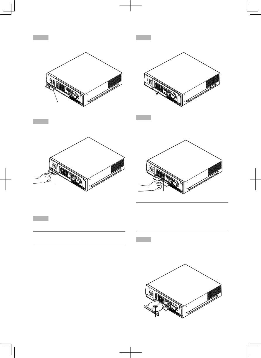
Insert an optional SDHC/SD memory card
Step 1
Open the SDHC/SD memory card slot.
Insert a DVD disc (commercially available)
Step 1
Open the DVD drive cover.
Pull the tab down.
SDHC/SD memory card slot
Step 2
Insert a SDHC/SD memory card to the slot until it clicks.
When inserting a SDHC/SD memory card, confirm that the label on the SDHC/SD memory card is upside and only the upper right corner of the card has different shape.
Step 3
Close the cover of the SDHC/SD memory card slot.
Note:
•When removing the SDHC/SD memory card from the slot, push the card until it clicks and pull it up straight.
Pull the tab down.
Step 2
After confirming that the power of the recorder is on, press the eject button located at the center of the DVD drive and pull the disc tray gently.
Eject button
Note:
•After copying the recorded data on a DVD, perform the procedure to eject the DVD. ( Operating Instructions (PDF))
Otherwise, the tray may not open even after the eject button is pressed.
Step 3
Place a disc with the label side up and fit the hole of the disc to the center (spindle) of the tray. Then, push the tray gently. Click sound will be heard and the inserted disk will be set.
Spindle
18

Step 4
Push the tray to the end. Click sound will be heard and the tray will be fixed.
Step 5
Close the DVD drive cover.
Important:
•When opening/closing the DVD drive tray, do not apply force on the tray.
•When not using the DVD drive, close the disc tray.
•When removing the disc from the tray, press the spindle to detach the disc. If trying to detach the disc forcibly, it can damage both the disc and the DVD drive.
19
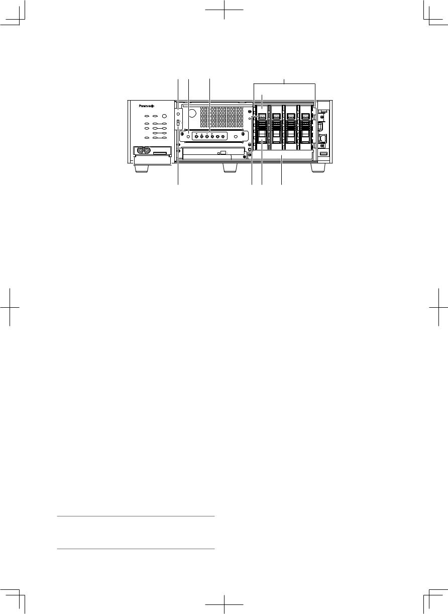
Behind the front cover
Refer to page 21 for descriptions of how to detach the front cover.
|
|
|
|
q w |
e |
|
|
t |
|
|
|
|
|
|
|
|
|
|
r |
|
|
|
|
|
|
|
|
|
ALARM |
USE |
|
|
|
|
|
|
|
|
ERROR |
ALARM |
|
RESET |
|
|
|
|
|
|
|
|
|
|
|
|
|
STS A/F |
STS |
A/F |
STS |
A/F |
STS |
A/F |
||
|
|
|
|
|
|
|||||||
ALARM |
|
|
|
RAID |
|
|
|
|
|
|
|
|
STS |
|
A/F |
|
|
|
|
|
|
|
|
|
|
SUSPEND |
HDD 1 |
|
|
|
|
|
|
|
|
|
||
TIMER |
|
HDD 2 |
|
|
|
|
|
|
|
|
|
|
|
|
HDD 3 |
|
|
|
|
|
|
|
|
|
MAINTENANCE |
|
|
|
|
|
ESC |
SET |
|
|
|
|
|
|
OPERATE |
|
|
|
|
|
|
|
|
|
|
||
|
HDD 4 |
|
|
|
|
|
|
|
|
|
|
|
|
|
|
|
|
|
|
|
|
|
|
|
MOUSE |
|
|
|
|
y |
|
u i |
|
o |
|
|
|
|
qUse button [USE]
Use this button when adding/replacing the HDD units, or when changing the operational mode.
Install/remove HDD units ( page 52)
Determine the operational mode of the hard disk drives ( page 54)
wDummy board
When installing an optional RAID board (WJ-HDB601), remove the dummy board and install it.
eOperation button
Use this button to operate the menu during the front cover is open. Refer to page 17 for further information
about the menu operation button. CDA B: Same as the arrows button ESC: Same as the [SETUP/ESC] button SET: Same as the [SET] button
rHDD canister
Locally procured hard disk drives are installed in these canisters. Refer to page 133 for how to add/replace the hard disk drives. Contact your dealer about purchasing hard disk drives.
tHDD canister slot
At the time of shipment from the factory, 4 canisters have been already installed in these slots. Up to 4 hard disk drives can be installed.
yRAID switch [RAID]
Use this switch to change the operational mode of the
hard disk drives (Single/RAID5/RAID6). ( Page 54) S: Single mode
R5: RAID 5 mode R6: RAID 6 mode
Default: S
Important:
•Do not change the operational mode of the hard disk drives after running the system. If it is changed, it may become impossible to read recorded data correctly.
uHDD indicator
These indicators will not light/blink. Check the status of the hard disk drives by the HDD indicators (+ page 16) on the front cover.
iRemoval knob
Use this knob to remove an HDD unit.
oHDD unit brace
This brace is provided for transportation. It is necessary to remove this brace when installing hard disk drives. When this product is to be transported, it is necessary to attach the brace.
When this product is not to be transported anymore, it does not affect the operation of the recorder even with the brace attached.
20
How to detach the front cover
Step 1
(When detaching the front cover while the power is on) Hold down the [ALARM RESET] button and the [MONITOR] button (for more than 2 seconds).
→ The power of the front cover will be turned off.
Step 2
Open the maintenance port cover and the DVD drive cover, and then remove the fixing screws (x3).
Cable clamp
Connection


 cable
cable 


Connector
DVD drive cover
Maintenance port cover (Pull up the bottom side of cover.)
Step 3
Pull the right side of the front cover first, and then detach the front cover.
Note:
•Before disconnecting the cable, be sure to turn off the power of front cover.
How to attach the front cover
Step 1
Connect the connection cable of the front cover.
When connecting the connection cable, twist the connection cable around the tab of the cable clamp.
( Reference illustration for step 4 of "How to detach the front cover")
Step 2
Put the tab (on the left of the front cover) into the hole, and then attach the front cover.
Hole
Tab 


Step 4
Disconnect the connection cable of the front cover.
• Detach the cables from the cable clamp on the front cover.
•Disconnect the cable while holding down the tab of the connector.
Step 3
Fasten the detached screws (x3), and then close the cover.
Step 4
(When attaching the front cover while the power is on) Press the [ALARM RESET] button.
→ The power of the front cover will be turned on.
21
Note:
•After attaching the front cover to the recorder, be sure to turn on the power of front cover.
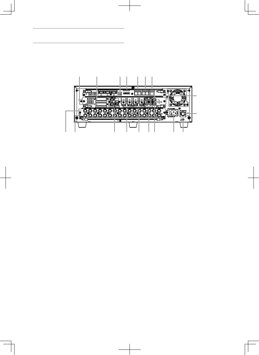
■ Rear view
|
q |
|
w |
|
|
|
e r |
|
t y u |
|
|
|
||||||
|
|
|
|
|
EXT STORAGE |
|
|
MODE |
|
DATA |
RS485(CAMERA) |
10/100BASE-T |
|
|
|
|||
|
|
|
3 |
|
2 |
|
1 |
|
123 4567 8 |
|
|
2 |
1 |
|
|
|
|
i |
|
|
|
|
|
|
|
|
|
|
|
|
|
|
|
|
|||
|
|
|
|
|
|
|
1 |
|
|
|
|
|
3 |
1 |
|
|
|
|
|
|
|
|
|
|
|
|
|
|
|
|
|
|
|
|
|||
|
|
|
|
|
|
|
MONITOR |
|
|
|
|
|
|
|
IN |
|
|
|
|
|
|
|
|
|
|
OUT |
|
|
|
|
|
|
|
|
|
|
|
|
|
|
|
ALARM |
|
|
2 |
|
|
|
|
|
|
|
CASCADE |
|
|
|
|
|
|
|
|
|
|
|
2 |
1 |
2 |
1 |
|
|
OUT |
|
|
||
|
|
|
|
|
|
|
|
|
|
|
|
|
||||||
|
|
|
ALARM/CONTROL |
OUT-CASCADE-IN |
|
CASCADE IN |
OUT |
MONITOR OUT(HD) |
4 |
2 |
AUDIO |
|
|
|
||||
|
|
|
|
AUDIO IN |
OUT |
|
|
|
||||||||||
|
16 |
15 |
14 |
13 |
12 |
11 |
10 |
9 |
8 |
7 |
6 |
5 |
4 |
3 |
2 |
1 |
POWER |
|
|
IN |
|
|
|
|
|
|
|
|
|
|
|
|
|
|
|
ON |
|
|
|
|
|
|
|
|
|
|
|
7 |
|
|
|
|
|
|
! |
|
|
|
|
|
|
|
|
|
|
|
|
|
|
|
|
1 |
|
||
|
|
|
|
|
|
|
|
|
|
|
|
|
|
|
|
OFF |
||
|
OUT |
|
|
|
|
|
|
|
|
|
|
|
|
|
|
OUT |
||
|
|
|
|
|
|
|
|
|
|
|
|
|
|
|
|
|
||
|
16 |
15 |
14 |
13 |
12 |
11 |
10 |
9 |
8 |
7 |
6 |
5 |
4 |
3 |
2 |
|
|
|
|
|
|
|
|
|
|
|
VIDEO |
|
|
|
|
|
|
AC IN |
SIGNAL |
|
|
|
|
|
|
|
|
|
|
|
|
|
|
|
|
|
|
|
||
|
|
|
|
|
|
|
|
|
|
|
|
|
|
|
|
|
GND |
|
!2 |
!3 |
|
|
|
|
!4 |
|
!5 |
|
!6 |
|
!7 !8!1 o |
|
|||||
qAlarm/Control connector (D-sub 25-pin) [ALARM/ CONTROL]
Connect a control switch to control the recorder using an external device such as a buzzer or a lamp.
( Page 44)
wAlarm connector (D-sub 25-pin) [ALARM]
Connect an external device such as a sensor, door switch, etc. to this connector. ( Page 48)
eExternal storage connector 1-3 [EXT STORAGE]
Connect the optional extension unit (WJ-HDE400) to this connector using the dedicated connection cable provided with the extension unit. ( Page 33)
rMode switch [MODE]
Determine the operational mode of the recorder using this switch. ( Page 51)
tDATA port [DATA]
Connect a PS·Data compatible device to this port. ( Page 35)
yRS485 port [RS485/CAMERA]
Connect an RS485 combination camera to this port. ( Page 42)
uNetwork port [10/100BASE-T]
Connect this recorder to a network (10BASE-T/ 100BASE-TX) using this port. When the recorder is connected to a network, it is possible to operate the recorder from a PC via a network.
iAudio cascade input/output connector (RCA pin jack) [CASCADE IN, OUT])
Use this connector for audio output from another recorder when it is connected in cascading connection.
oSIGNAL GND terminal
Connect this terminal to the SIGNAL GND terminals of the devices in the system for signal ground. When operating the recorder and the devices in the system without signal ground, oscillation or noise may be produced.
!0 Power button [POWER]
Press this button to turn on/off the power of the recorder. When this button is pressed again, the operation is finished and the power is turned off.
!1 Power inlet [AC IN]
Connect the provided power cord to this inlet. The power plug is a 2-conductor plug with grounding terminal type.
!2 Video input connector 1 to 16 (BNC) [VIDEO IN 1 to 16]
Connect system cameras and combination cameras to these connectors. When connecting combination cameras, connect them to the video input connector 1-8 (coaxial communication compatible).
!3 Video output connector 1 to 16 (BNC, active loop through) [VIDEO OUT 1 to 16]
Images input to the video out connectors 1-16 will be output from these connectors. When the power is off, images will not be output to the video output connector 1-16.
22

!4 Monitor output connector (BNC) [MONITOR OUT 1, 2]
Connect a monitor to this connector. Monitor output connector 1 shall be used to connect a monitor (Monitor 1) to display live image only. Monitor output connector 2 shall be used to connect a monitor (Monitor 2) to display live/recorded images and the setup menus. Monitor output connector 2 can also be used for cascade output.
!5 Cascade input connector (BNC/HDMI) [CASCADE IN 1, 2]
Connect the other recorder in cascading connection (output) when connecting multiple recorders.
!6 Monitor output connector (HDMI) [MONITOR OUT (HD) 1, 2]
This connector functions in the same manner as the monitor output connector (BNC).
!7 Audio input connector 1-4 (RCA pin jack) [AUDIO IN 1 to 4]
Use this connector for LINE input. A device such as a microphone amplifier can be connected to input audio. The entered audio will be output from the audio output connector.
!8 Audio output connector (RCA pin jack) [AUDIO OUT 1, 2]
Use this connector to output audio. Audio entered to the audio input connector will be output from this connector. When playing recorded images, audio recorded together with images will be output. When the recorders are connected in cascading connection, audio from them are also be output.
How to use the power cord plug brace
Brace the power cord plug.
Step 1
Fix the power cord plug firmly with the power cord plug brace.

 POWER
POWER
ON OFF
Power cord plug brace
23

User/Host management
It is necessary to register users who operates the recorder and hosts (PC) that accesses the recorder via a network such as a LAN. Up to 32 users and up to 8 hosts can be registered.
The following information can be registered as user information and host information.
Item |
Description |
Remarks |
|
|
|
User name |
User name is to be registered to log in to the recorder. |
This setting item can be configured only in |
|
It will be required to log in to the recorder. |
the user registration. |
|
|
|
IP address |
IP address of a PC is to be registered to access the |
This setting item can be configured only in |
|
recorder. When "On" is set for "Host registration", only |
the host registration. |
|
PCs with the registered IP addresses can access the |
|
|
recorder. |
|
Password |
Password is to be registered to log in to the recorder |
|
together with the user name. It will be required to log in |
|
to the recorder. |
This setting item can be configured only in the user registration.
Level |
Level indicates availability of the functions for users. |
|
Refer to page 112 for the operable functions for each |
|
level. |
Priority level |
Priority level indicates the operational priority. When |
|
multiple users/hosts tried to operate the same, only a |
|
user/host with a higher priority can operate. |
In the following cases, the operational right will be given to a user/host with a higher priority.
•When another user tried to log in while the other user is already being logged in.
•When another user tried to control a camera that is being controlled by the other user
Default screen |
Camera channels from which live images are to be |
|
displayed on Monitor 1, Monitor 2 and the PC monitor |
|
just after the login can be determined. |
|
|
Camera partitioning |
Operational range of each camera channel for users/ |
|
hosts can be determined. |
|
|
Users and hosts will be handled differently depending on how to access the recorder (between when the recorder is directly operated and when the recorder is operated via a network).
When operating the recorder directly
Operate the recorder while monitoring the monitor connected to the recorder. There are 3 ways of how to operate the recorder directly.
•Operate using the buttons on the front cover of the recorder.
•Operate using a mouse connected to the front cover of the recorder.
•Operate from a PS·Data compatible system controller.
Note:
•When controlling a camera connected to a coaxial communication unit from a system controller compatible with PS·Data, the priority level configured on the recorder will not be applied since it is controlled directly from the system controller. (The priority will be given to the latest operation.)
It is impossible to log in to the recorder from the front cover (using the buttons or the mouse) and from the system controller at the same time (except logging in using the same user name).It is impossible to log in to the recorder regardless of the priority level even if a user tried to log in when another user is already logged in.
24

Note:
•When operating from a system controller compatible with PS·Data, log in to the recorder automatically as the user registered in "PSD user" on the "Basic" tab under "User mng.".
•When no operation is made for approx.2 minutes after logging in from a system controller compatible with PS·Data, the PSD user will automatically be logged out.
•When trying to log in as the same user name used by a user who is already logged in, both users will be authorized to log in regardless of the priority level.
When operating from a PC via a network
Operation of the recorder can be made using a PC via a network. Up to 8 hosts (PCs) can access the recorder concurrently. When trying to log in to the recorder even though 8 hosts (PCs) are already accessing the recorder, the host (PC) with the lowest priority will forcibly be logged out.
When accessing the recorder from a PC via a network, the authentication method is different depending on the "User authentication" and "Host authentication" settings of the "Basic" tab under "User mng.".
User authentication |
Host authentication |
User/Host to log in |
Remarks |
|
setting |
setting |
|||
|
|
|||
|
|
|
|
|
Off |
Off |
Log in as an administrator. |
|
|
|
|
|
|
|
On |
Off |
Log in as a registered user. |
The login window will be |
|
|
|
|
displayed. |
|
|
|
|
|
|
Off |
On |
Log in as a registered host. |
The login window will not |
|
|
|
|
be displayed. |
|
|
|
|
|
|
On |
On |
Log in as a registered user. |
It is impossible to log in to |
|
|
|
|
the recorder from an |
|
|
|
|
unregistered PC. |
|
|
|
|
|
25

Basic operation
To directly operate the recorder, there are 2 ways of how to operate it: operations using the buttons on the front cover and operations using a mouse connected to the recorder.
Operations using the buttons on |
Operations using a mouse |
the front cover |
|

 Digital Disk Recorder WJ-HD616


 Digital Disk Recorder WJ-HD616
The recorder can be operated using the buttons on the front cover to which the functions are assigned.
Refer to the "Major operating controls and their functions" section ( page 16) for further information about the functions assigned to each button.
Refer to Operating Instructions (PDF) for how to operate each function.
When you find "Select XX button" in the operating instructions, move the cursor onto the XX button using the arrows button (CDAB) and press the [SET] button.
SET
The recorder can be operated using a mouse connected to the mouse port on the front cover.
Move the mouse cursor onto a button or a tab on the screen of Monitor 2, and then click on it
When right-clicking, the operation panel representing the front cover (the monitor operation button and the camera selection button on the front cover) will be displayed on Monitor 2.The camera selection and monitor selection can be made by moving the cursor on the button and click it. When no operation is made for 10 seconds while the operation panel or the setup menu is displayed, the mouse cursor will disappear. The mouse cursor will be displayed when the mouse is moved.
Refer to Operating Instructions (PDF) for how to operate each function.
When you find “Select XX button" in the operating instructions, click the XX button.
26

Operations flow
The operation flow of the recorder is as follows.
zRack mounting ( Page 28)
xConnections ( Page 29)
cInstallation of the hard disk drives
( Page 52)
vDetermination of the operational mode
( Page 54)
bStartup ( Page 55)
|
|
|
n |
Configuration of the settings for the |
|
|
quick setup. ( Page 63) |
|
|
|
|
m |
Configuration of the recording area |
|
|
setting of the hard disk drives. ( |
|
|
|
Page 126) |
|
|
|
, |
Setup ( Page 57) |
|
|
|
|
|
Start operation |
|
|
When necessary |
|
. |
Replacement/addition of hard disk |
|
|
|
drives ( Page 133) |
zInstall the recorder in the rack.
Go to step x when not installing it in the rack.
xConnect the recorder to each device.
When using an optional extension unit, install hard disk drives in the optional extension unit (WJ-HDE400) and connect to the recorder. ( Page 33)
cInstall hard disk drives in the recorder.
When using an optional RAID board (WJ-HDB601) or an optional DVD drive (WJ-HDB611), install it.
vReboot the recorder after determining the operational mode if necessary such when using the RAID function. When not installing an optional RAID board (WJ-HDB601), go to step 5.
bTurn on the power of the recorder.
When using optional extension units (WJ-HDE400), turn the power of all the extension units before turning on the power of the recorder.
nConfigure the settings such as the current time and date setting, schedule recording settings, etc.
mChange the recording area setting or format the recording area of the hard disk drive if necessary such when it is necessary to assign the event recording area to the hard disk drive.
, Configure the settings required for operation.
The hard disk drives can be formatted/replaced without turning off the power of the recorder even when one of them becomes faulty.
27

Rack mounting
Install the recorder in an EIA standard rack.
Equivalent to EIA standard rack (not manufactured by Panasonic): EIA 19-inch rack type (Depth: 550 mm or more)
Note:
• Use four M5 x 12 screws (locally procured) to install the recorder in a rack.
Step 1
Remove the five rubber feet from the bottom of the recorder using a flathead screwdriver.
Use a screwdriver to remove the screws holding the rubber feet.
Remove the rubber feet.
Step 2
Attach the rack handles to the rack mount brackets.
Fix them firmly using the screws for the rack handle (x4) and the washers (x4).
Screw for rack handle
Washer
 Rack mount bracket

 Washer
 Rack handle
Step 3
Place the rack mount brackets on both sides of the recorder. Fix them firmly with the rack mount bracket fixing screws (x6).
Screw for rack mount bracket (provided)
Rack handle
Rack handle Rack mount bracket (provided)
Step 4
Install the recorder in the rack.
Fix them firmly using the rack mount screws.
Rack mount screws
M5 x 12 (locally procured)
Important:
•Keep the temperature in the rack below +45 °C
{+113 °F}.
•It is recommended to install cooling fans or equivalents to keep the temperature in the rack below +30 °C {+86 °F}.
•When installing the recorder in the rack, make a space of
1U (44 mm {1-23/32"}) above and below the recorder for ventilation.
•Do not block the ventilation openings or slots to prevent the recorder from overheating.
28

Connections
Connection of cameras
Up to 16 cameras (system cameras or combination cameras) can be connected to the video input connector 1-16.
Important:
•When using with a Panasonic's matrix switcher or a coaxial communication unit, make sure that the loop-through output connection (of each video input) to the recorder are correctly made. When a monitor output or a spot output is connected to the video input connector of the recorder, noise may be produced upon switching camera channels or images of few seconds before switching camera channels may be displayed/recorded. When a monitor output or a spot output is connected to the video input connector of the recorder, noise may be produced upon switching camera channels or images of few seconds before switching camera channels may be displayed/recorded.
•Connect the power plug of the recorder at the very end of connections.
•When connecting combination cameras to the WJ-HD616K, connect them to the video input connector 1 - 8 (coaxial connection compatible).
•It is impossible to connect a VCR to the video input connector.
Mode switch setting (default)
Note:
• When not using the DATA port and the RS485 port, do not change the setting from the default.
Mode switch setting (default)
ON

1 2 3 4 5 6 7 8
Note: When not using the DATA port and the RS485 port, do not change the setting from the default.
Microphone
Amplifier
|
|
|
|
|
|
|
|
|
|
|
|
|
|
|
|
Recorder |
|
|
|
|
EXT STORAGE |
|
|
MODE |
|
DATA |
RS485(CAMERA) |
10/100BASE-T |
|
|
|||
|
|
3 |
|
2 |
|
1 |
|
123 4567 8 |
|
|
|
|
|
|
|
|
|
|
|
|
|
|
|
|
|
|
2 |
1 |
|
|
|
|
|
|
|
|
|
|
|
|
|
|
|
|
|
|
|
|
||
|
|
|
|
|
|
1 |
|
|
|
|
|
3 |
1 |
|
|
|
|
|
|
|
|
|
MONITOR |
|
|
|
|
|
|
|
IN |
|
|
|
|
|
|
|
|
OUT |
|
|
|
|
|
|
|
|
|
|
|
|
|
ALARM |
|
|
2 |
|
|
|
|
|
|
|
CASCADE |
|
|
|
|
|
|
|
|
|
2 |
1 |
2 |
1 |
|
|
OUT |
|
|
|
|
|
|
|
|
|
|
|
|
|
|
|
|||||
|
|
ALARM/CONTROL |
OUT-CASCADE-IN |
|
CASCADE IN |
OUT |
MONITOR OUT(HD) |
4 |
2 |
AUDIO |
|
|
||||
|
|
|
AUDIO IN |
OUT |
|
|
||||||||||
16 |
15 |
14 |
13 |
12 |
11 |
10 |
9 |
8 |
7 |
6 |
5 |
4 |
3 |
2 |
1 |
POWER |
IN |
|
|
|
|
|
|
|
|
|
|
|
|
|
|
|
ON |
|
|
|
|
|
|
|
|
|
7 |
|
|
|
|
|
|
|
|
|
|
|
|
|
|
|
|
|
|
|
|
|
1 |
|
|
|
|
|
|
|
|
|
|
|
|
|
|
|
|
|
OFF |
|
OUT |
|
|
|
|
|
|
|
|
|
|
|
|
|
|
OUT |
|
|
|
|
|
|
|
|
|
|
|
|
|
|
|
|
||
16 |
15 |
14 |
13 |
12 |
11 |
10 |
9 |
8 |
7 |
6 |
5 |
4 |
3 |
2 |
|
|
|
|
|
|
|
|
|
VIDEO |
|
|
|
|
|
|
AC IN |
SIGNAL |
|
|
|
|
|
|
|
|
|
|
|
|
|
|
|
|
||
|
|
|
|
|
|
|
|
|
|
|
|
|
|
|
|
GND |
• • • |
• • • |
System cameras
(Video input connector 9 - 16)
Combination cameras (Video input connector 1 - 8)
29

Connection of monitors
Connect monitors to the monitor output connector.
Connect a monitor to be used to display live images only to the monitor output connector 1.
Connect a monitor to be used to display not only live images but also recorded images and setup menu to the monitor output connector 2.
The monitor can be connected using a BNC cable or a HDMI cable. (There is no difference in contents to be output to each monitor.)
When connecting a monitor using a BNC cable
Monitor 1 |
Monitor 2 |
* When outputting audio |
Connect a powered speaker (locally procured) |
Powered speaker
|
|
|
|
|
|
BNC cable |
|
|
|
|
|
|
Audio cable |
|
||
|
|
|
|
|
|
(locally procured) |
|
|
|
|
|
(locally procured) |
|
|||
Recorder |
|
|
|
|
|
|
|
|
|
|
|
|
|
|
|
|
|
|
|
|
EXT STORAGE |
|
|
MODE |
|
DATA |
RS485(CAMERA) |
10/100BASE-T |
|
|
|||
|
|
3 |
|
2 |
|
1 |
|
123 4567 8 |
|
|
|
|
|
|
|
|
|
|
|
|
|
|
|
|
|
|
|
2 |
1 |
|
|
|
|
|
|
|
|
|
|
1 |
|
|
|
|
|
3 |
1 |
|
|
|
|
|
|
|
|
|
MONITOR |
|
|
|
|
|
|
|
IN |
|
|
|
|
|
|
|
|
OUT |
|
|
|
|
|
|
|
|
|
|
|
|
|
ALARM |
|
|
2 |
|
|
|
|
|
|
|
CASCADE |
|
|
|
|
|
|
|
|
|
2 |
1 |
2 |
1 |
|
|
OUT |
|
||
|
|
|
|
|
|
|
|
|
|
|
||||||
|
|
ALARM/CONTROL |
OUT-CASCADE-IN |
|
CASCADE IN |
OUT |
MONITOR OUT(HD) |
4 |
2 |
AUDIO |
|
|
||||
|
|
|
AUDIO IN |
OUT |
|
|
||||||||||
16 |
15 |
14 |
13 |
12 |
11 |
10 |
9 |
8 |
7 |
6 |
5 |
4 |
3 |
2 |
1 |
POWER |
IN |
|
|
|
|
|
|
|
|
|
|
|
|
|
|
|
ON |
|
|
|
|
|
|
|
|
|
7 |
|
|
|
|
|
|
|
|
|
|
|
|
|
|
|
|
|
|
|
|
|
1 |
|
|
|
|
|
|
|
|
|
|
|
|
|
|
|
|
|
OFF |
|
OUT |
|
|
|
|
|
|
|
|
|
|
|
|
|
|
OUT |
|
|
|
|
|
|
|
|
|
|
|
|
|
|
|
|
||
16 |
15 |
14 |
13 |
12 |
11 |
10 |
9 |
8 |
7 |
6 |
5 |
4 |
3 |
2 |
|
|
|
|
|
|
|
|
|
VIDEO |
|
|
|
|
|
|
AC IN |
SIGNAL |
|
|
|
|
|
|
|
|
|
|
|
|
|
|
|
|
||
|
|
|
|
|
|
|
|
|
|
|
|
|
|
|
|
GND |
30
 Loading...