


Panasonic WU-144ME1U9, U-96MF1U9E, U-96MF1U9, U-72MF1U9, U-72MF1U9E Installation Manual
...Operating Instructions
Intelligent Controller
Model No. CZ-256ESMC1U
Before operating the unit, read these operating instructions thoroughly and keep them for future reference.
85464609160011 |
1006 Kadoma, Kadoma City, Osaka, Japan |
|
CV6233189666 |
||
|
CZ-256ESMC1U_ .indb 1 |
2011/11/11 11:24:52 |
|
|
|
|
|
|
||
|
|
|
||
|
|
|
|
|
CZ-256ESMC1U
INTELLIGENT CONTROLLER
Operating Instructions
CZ-256ESMC1U_ .indb 2 |
2011/11/11 11:24:54 |
|
|
|
|
|
|
||
|
|
|
||
|
|
|
|
|
CONTENTS
1 IMPORTANT SAFETY INSTRUCTIONS ................................................................................... |
4 |
2 FEATURES OF THE SYSTEM .................................................................................................. |
8 |
3 SYSTEM CONFIGURATION...................................................................................................... |
9 |
4 NAMES AND FUNCTIONS OF PARTS................................................................................... |
10 |
5 QUICK REFERENCE............................................................................................................... |
13 |
6 USING THE SYSTEM .............................................................................................................. |
15 |
6.1 Powering the System On.................................................................................................. |
15 |
6.2 Names and Functions of Screen Parts............................................................................. |
15 |
6.2.1 Initial communications screen .................................................................................. |
15 |
6.2.2 Operating screen example ....................................................................................... |
16 |
6.3 Initial Settings................................................................................................................... |
18 |
6.3.1 System setting flow .................................................................................................. |
19 |
6.3.2 Setting the date, cut-off date, and distribution ratio calculation method................... |
22 |
6.3.3 Setting central addresses, unit names and tenant numbers .................................... |
24 |
6.3.4 Setting tenant names and distribution groups.......................................................... |
26 |
6.3.5 Making pulse meter settings..................................................................................... |
28 |
6.3.6 Clear accumulation data........................................................................................... |
30 |
6.4 Status Monitoring and Operation Screens ....................................................................... |
31 |
6.4.1 Displaying general information by tenant ................................................................. |
31 |
6.4.1.1 Operating units individually.......................................................................... |
32 |
6.4.1.2 Operating all units by tenant........................................................................ |
33 |
6.4.1.3 Operating all connected units...................................................................... |
34 |
6.4.2 Displaying detailed information by tenant................................................................. |
35 |
6.4.3 Displaying general information by zone ................................................................... |
36 |
6.4.4 Displaying detailed information by zone................................................................... |
37 |
6.4.5 Displaying and operating all indoor units ................................................................. |
38 |
6.5 Total Data and Manual Cut-Off Processing ...................................................................... |
39 |
6.5.1 Displaying total data by indoor unit .......................................................................... |
39 |
6.5.2 Displaying total data by tenant ................................................................................. |
40 |
6.5.3 Displaying total data by outdoor unit ........................................................................ |
41 |
6.5.4 Displaying pulse meter total data ............................................................................. |
42 |
6.5.5 Performing manual cut-off processing and saving data ........................................... |
43 |
6.5.5.1 Manual cut-off processing ........................................................................... |
43 |
6.5.5.2 Saving data.................................................................................................. |
44 |
6.5.5.3 Outputting distribution data in progress....................................................... |
44 |
6.5.5.4 Restoring data ............................................................................................. |
45 |
6.6 Air Conditioning Distribution Ratios and Energy Usage ................................................... |
46 |
6.6.1 Displaying distribution ratios and energy usage by indoor unit ................................ |
46 |
6.6.2 Displaying distribution ratios and energy usage by tenant....................................... |
47 |
6.6.3 Time zone totals and distribution.............................................................................. |
48 |
6.7 Maintenance and Test Runs............................................................................................. |
49 |
6.7.1 Checking inspection signs........................................................................................ |
49 |
6.7.2 Checking the alarm logs........................................................................................... |
50 |
6.7.3 Executing test runs................................................................................................... |
52 |
Main5Sub1
Main5Sub2
Main5Sub3
Main5Sub4
Main5Sub5
Main1Sub1
Main1Sub 2
Main1Sub 3
Main1Sub 4
Main1Sub 5
Main2Sub1
Main2Sub2
Main2Sub3
Main2Sub4
Main2Sub5
Main3 Sub1
Main3Sub2
Main4Sub1
Main4Sub 2
Main4Sub 3
Main5Sub1 refers to the explanation of main menu 5, sub menu 1.
2
CZ-256ESMC1U_ .indb 2 |
2011/11/11 11:24:54 |
|
|
|
|
|
|
||
|
|
|
||
|
|
|
|
|
6.8 Auxiliary Settings.............................................................................................................. |
53 |
6.8.1 Registering zone names........................................................................................... |
53 |
6.8.2 Setting zone numbers and management targets ..................................................... |
54 |
6.8.3 Programming timers................................................................................................. |
56 |
6.8.3.1 Programming daily timers............................................................................ |
56 |
6.8.3.2 Programming weekly timers ........................................................................ |
59 |
6.8.4 Setting Tenant holiday/Timer special day................................................................. |
60 |
6.8.5 Prohibiting remote control use.................................................................................. |
61 |
6.8.6 Setting distribution time zones ................................................................................. |
62 |
6.8.7 Setting special distribution days............................................................................... |
63 |
6.8.8 Indoor unit settings................................................................................................... |
64 |
6.8.9 Other settings........................................................................................................... |
65 |
6.8.9.1 Checking the connection configuration........................................................ |
65 |
6.8.9.2 Registering passwords ................................................................................ |
66 |
6.8.9.3 Selecting no-communications mode............................................................ |
66 |
6.8.9.4 Buzzer sounds............................................................................................. |
66 |
6.8.9.5 Initialization.................................................................................................. |
66 |
6.8.9.6 LCD auto off settings ................................................................................... |
67 |
6.8.9.7 Calibrating touch panels.............................................................................. |
67 |
6.8.9.8 Power off button .......................................................................................... |
68 |
6.8.10 WEB settings.......................................................................................................... |
69 |
6.8.10.1 Detailed server settings............................................................................. |
70 |
6.8.10.1.1 Receiving server settings ......................................................... |
71 |
6.8.11 User settings........................................................................................................... |
72 |
6.9 System Configuration Changes........................................................................................ |
74 |
6.9.1 When a system configuration change detected ....................................................... |
74 |
6.9.2 When system configuration may change ................................................................. |
75 |
7 ENTERING TEXT AND NUMBERS......................................................................................... |
76 |
7.1 Entering Numbers ............................................................................................................ |
76 |
7.2 Entering Text .................................................................................................................... |
77 |
8 CONNECTION OF EXTERNAL SIGNALS .............................................................................. |
79 |
8.1 Pulse Meter Input ............................................................................................................. |
79 |
8.2 All Stop Input .................................................................................................................... |
80 |
8.3 All Start Input.................................................................................................................... |
80 |
8.4 All-Unit Alarm Output........................................................................................................ |
81 |
8.5 All-Unit Operation Output ................................................................................................. |
81 |
9 TERMS..................................................................................................................................... |
82 |
10 CALCULATING AIR CONDITIONER DISTRIBUTION.......................................................... |
83 |
10.1 Calculating simple distribution........................................................................................ |
83 |
10.2 Calculating air conditioner energy usage ....................................................................... |
85 |
10.3 Calculating loaded distribution ....................................................................................... |
86 |
11 SUPPLEMENTARY INFORMATION-1................................................................................... |
87 |
12 SUPPLEMENTARY INFORMATION-2 .................................................................................. |
88 |
13 TROUBLESHOOTING........................................................................................................... |
91 |
14 MAINTENANCE..................................................................................................................... |
93 |
15 SPECIFICATIONS.................................................................................................................. |
94 |
16 INSTALLATION (ELECTRIC) AND SERVICE INSTRUCTIONS........................................... |
96 |
3
Main6 Sub1
Main6Sub2
Main6 Sub3
Main6Sub4
Main6Sub5
Main6Sub6
Main6 Sub7
Main6Sub8
Main6Sub9
Main6Sub10
Main6Sub11
CZ-256ESMC1U_ .indb 3 |
2011/11/11 11:24:55 |
|
|
|
|
|
|
||
|
|
|
||
|
|
|
|
|

1 IMPORTANT SAFETY INSTRUCTIONS
Before using the system, be sure to read these “Important Safety Instructions”.
The precautions given in this manual consist of specific
“ Warnings” and “
 Cautions”. They provide important safety related information and are important for your safety, the safety of others, and trouble-free operation of the system. Be sure to strictly observe all safety procedures.
● The labels and their meanings are as described below.
 Warning
 Caution
● Meaning of symbols
This refers to a hazard or unsafe procedure or practice which can result in severe personal injury or death.
This refers to a hazard or unsafe procedure or practice which can result in personal injury or product or property damage.
Indicates “Warning” or “Caution”.
Indicates “Prohibited”.
Indicates an action that should always be performed.
● After reading this manual, save it in a convenient place.
Be sure to provide this manual to any person who may use the product.
Installation Precautions
Warning
Do not install yourself
Have dealer install
Installation should always be performed by your dealer or a professional service provider.
Electric shock or fire may result if an inexperienced person performs any installation or wiring procedures incorrectly.
Use only specified air conditioners
Always use only air conditions specified by the dealer.
Specified air conditioners
Electrical work must be carried out by qualified personnel
Contact your dealer for installation. Do not attempt to install the product yourself.
4
CZ-256ESMC1U_ .indb 4 |
2011/11/11 11:24:57 |
|
|
|
|
|
|
||
|
|
|
||
|
|
|
|
|

1 IMPORTANT SAFETY INSTRUCTIONS
Location
 Caution
Do not install in damp locations or |
Do not install under direct sunlight or |
locations subject to vibrations |
in places near heat sources |
Damage to the product can result. |
The product may be damaged. |
Do not install near sources of noise |
Avoid static electricity during cabling |
Malfunctions can result. |
work |
|
Before starting cabling work, touch |
|
ground to discharge static electricity |
|
from the body. |
Elevators, Automatic doors, Industrial machinery, etc
Avoid installation in the following |
Keep televisions, radios, PCs, etc, |
|
locations |
at least 4 ft away from |
|
● Locations subject to inflammable |
the central controller, |
|
gas leakage |
indoor units, and remote |
|
● Near beaches or other places |
||
controllers. |
||
with a large amount of salt |
||
● Hot springs or other locations |
Picture breakup and noise can occur. |
|
subject to sulfuric gas |
|
●Locations near water and oil (including industrial lubricants), and water and oil sprays
●Locations with large changes in voltage
●Near machines generating electromagnetic waves
●Locations close to organic solvents
Do not use heaters near the Intelligent Controller
Plastic parts of the Intelligent Controller may be deformed or discolored.
5
CZ-256ESMC1U_ .indb 5 |
2011/11/11 11:24:58 |
|
|
|
|
|
|
||
|
|
|
||
|
|
|
|
|

1 IMPORTANT SAFETY INSTRUCTIONS
Precautions for Use
 Warning
Do not touch switches with wet |
Protect the Intelligent Controller from |
|||
hands |
water |
|||
|
|
|
Electric shock and damage to the |
Damage to the system can result. |
|
|
|
system can result. |
|
|
|
|
|
|
|
|
|
|
|
Prohibited |
Prohibited |
|
Stop the system and turn the power off if you sense unusual smells or other irregularities
Continuing operation when the system is out of order can result in electric shock, fire,
and damage to the system.
Contact your dealer
Turn off the power.
 Caution
Do not drop the system or subject it to strong shocks
Damage to the system can result.
Use only fuses with the correct capacity
Use of pins or copper wire can result in fire and damage to the
system.
Prohibited |
Prohibited |
|
Use only the specified power source
Use of any other power source can result in fire and damage to the system.Use single-phase 100-240V power.
6
CZ-256ESMC1U_ .indb 6 |
2011/11/11 11:24:58 |
|
|
|
|
|
|
||
|
|
|
||
|
|
|
|
|

1 IMPORTANT SAFETY INSTRUCTIONS
 Caution
Use the special supplied touch pen
Touching the touch panel with any pen other than the supplied touch pen can damage the system.
Prohibited
Moving and Repair Precautions
 Warning
Do not disassemble or repair
Never disassemble or repair the system yourself. Contact your dealer for repair. Electric shock or fire may result if an inexperienced person attempts to repair the system.
Prohibited
Contact your dealer before moving the system
Contact your dealer
Contact your dealer or a professional service provider about moving and reinstalling the system. Electric shock or fire may result if an inexperienced person performs any installation procedures
incorrectly.
Do not touch the LCD if it is leaking
If the touch panel is damaged, the liquid crystal from inside the display may leak out. Do not ingest the liquid or allow it to contact your skin.
If accidental contact with skin occurs, rinse the area of contact thoroughly under running water for at least 15 minutes.
Prohibited |
If accidental swallowing occurs, rinse the inside of your mouth thoroughly with water. Drink |
plenty of water and induce vomiting, and then seek immediate medical attention. |
Note: ●This equipment has been tested and found to comply with the limits for a Class B digital device, pursuant to part 15 of the FCC Rules. These limits are designed to provide reasonable protection against harmful interference in a residential installation. This equipment generates, uses and can radiate radio frequency energy and, if not installed and used in accordance with the instructions,may cause harmful interference to radio communications. However, there is no guarantee that interference will not occur in a particular installation. If this equipment does cause harmful interference to radio
or television reception, which can be determined by turning the equipment off and on, the user is encouraged to try to correct the interference by one or more of the following measures:
•Reorient or relocate the receiving antenna.
•Increase the separation between the equipment and receiver.
•Connect the equipment into an outlet on a circuit different from that to which the receiver is connected.
•Consult the dealer or an experienced radio/TV technician for help.
●FCC Caution: To assure continued compliance, follow thw attached installation instructions.
Any changes or modifications not expressly approved by the party responsible for compliance could void the user’s authority to operate this equipment.
7
CZ-256ESMC1U_ .indb 7 |
2011/11/11 11:24:59 |
|
|
|
|
|
|
||
|
|
|
||
|
|
|
|
|

2 FEATURES OF THE SYSTEM
The Intelligent Controller is a centralized air conditioning management system dedicated to PAC and GHP for small and medium sized buildings.
● Number of connectable units········• By connecting communication adaptors to one Intelligent Controller, up to 256 indoor units can be connected.
•Up to 120 outdoor units can be connected.
●Display··········································• Touch panel type 6.5-inch TFT color (640x480 pixel VGA) LCD
display
● Operation functions·······················• Start and stop, temperature settings, operation mode selection, fan speed settings, fan direction settings, ventilation etc.
● Operating monitoring ····················• All unit monitoring of operation status (operating/stopped, operation mode, alarms)
•Display of alarm logs
•One-operation checking of all filter cleaning signs and engine oil inspection signs
•External output of all errors, external output of all operations (relay connections)
●Program timers…………………… • Up to 50 types of weekly timers can be programmed by combining
50 types of daily timers (50 times per day).
●Air conditioning energy
distribution·····································• Recording and display of accumulated operating time and total number
of operations for each indoor unit.
•Calculation of gas and electricity distribution ratios and energy amounts used (m3, kWh) for each indoor unit and each tenant.
•Distributions are available in two modes: the “simple distribution” calculated based on the operating time and “loaded distribution” calculated based on the actual air conditioning capacity, respectively. (In order to make operation in the “Loaded distribution” mode, the air conditioner side needs to be adaptable to the “Loaded distribution”.
•Distribution by time zones (regular hours, out of hours, special days).
•Recording of up to past 24 months of cut-off data.
Terms and abbreviations used in this manual and in the system software
Full term |
Abbreviation |
Adaptor address |
Adaptor |
Link system address |
Link system |
Outdoor unit system address |
Outdoor unit system, Outdoor unit, Outdoor system, Outdoor, O/D |
Indoor unit address |
Indoor unit, Indoor, I/D |
Distribution group number |
Distribution group No., Distribution group |
Tenant number |
Tenant No., Tenant |
Zone number |
Zone No., Zone |
Unit name |
Unit |
Air conditioning distribution ratio |
Distribution ratio, Distr. ratio |
Central control address |
Central address, CNTR |
Thermostat |
T/S |
* For more information about terms, see “9 Terms”.
8
CZ-256ESMC1U_ .indb 8 |
2011/11/11 11:24:59 |
|
|
|
|
|
|
||
|
|
|
||
|
|
|
|
|
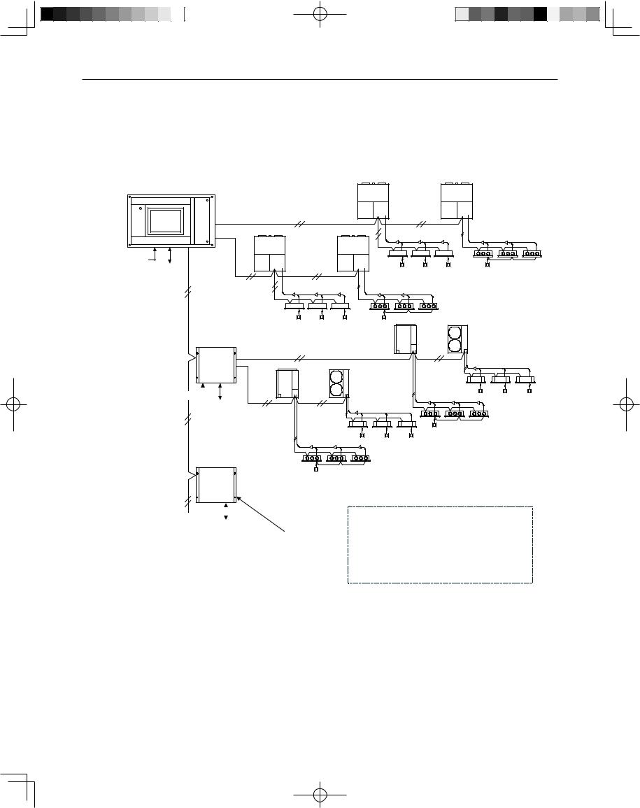
3 SYSTEM CONFIGURATION
System Configuration Example
Intelligent Controller
|
Indoor/outdoor control wire |
Link system |
|
|
(non-polar) |
No.1 |
|
Pulse meter x 3 |
Link system |
||
No.2 |
|||
All-unit signal x 4 |
|||
|
|
||
Indoor/outdoor control wire (non-polar)
Communication adaptor
control wire Communication adaptor (RS-485, polar)
Link system No.3
Pulse meter x 3 
All-unit signal x 4
Link system
No.4
Communication adaptor
|
Pulse meter |
|
|
|
|
|
|
|
|
|
|
|
|
G |
|
|
|
Maximum number of connections |
|
|
|
All-unit signal x 4 |
|
||||
|
|
|
||||
|
|
|
|
|||
W |
|
|
Indoor units: |
256 (64/link x 4) |
||
|
|
|
Independent installation |
|||
G: Gas flow meter |
|
|
Outdoor units: |
120 (30/link x 4) |
||
|
|
without link system |
||||
|
|
Communication adaptors: |
7 |
|||
W: Electricity meter |
|
|
||||
|
|
connection also possible |
||||
|
|
Link systems: |
4 |
|||
|
|
|
|
|||
|
|
|
|
|
||
(Indoor/outdoor control wires)
*When connecting link systems (inter-unit control wires), always connect beginning with LINK1 and LINK2 on the Intelligent Controller. Up to 4 link systems can be connected.
9
CZ-256ESMC1U_ .indb 9 |
2011/11/11 11:25:00 |
|
|
|
|
|
|
||
|
|
|
||
|
|
|
|
|
4 NAMES AND FUNCTIONS OF PARTS
● Front Panel
Power indicator |
Touch panel type color LCD display |
lights to show that the intelligent |
Displays operating screens. Use |
controller is powered on. |
the supplied touch pen to operate. |
POWER |
PC Card and touch pen storage cover
Push the cover to open it. The compartment inside is used to store the touch pen and to insert and eject PC Cards for backup.
Touch pen
Used to carry out operations on the LCD display.
 PC Card socket
Used to insert optional PC Cards for backup.
10
CZ-256ESMC1U_ .indb 10 |
2011/11/11 11:25:00 |
|
|
|
|
|
|
||
|
|
|
||
|
|
|
|
|

4 NAMES AND FUNCTIONS OF PARTS
● Rear Panel
11
CZ-256ESMC1U_ .indb 11 |
2011/11/11 11:25:01 |
|
|
|
|
|
|
||
|
|
|
||
|
|
|
|
|

4 NAMES AND FUNCTIONS OF PARTS
● Right side panel
Power connector panel
AC100V-240V power connector panel.
Power switch |
|
|
|
|
Powers the Intelligent Controller |
|
|||
on and off. |
|
|
|
|
|
|
|
OFF |
ON |
Communications connector panel |
|
|||
1 |
|
ADAPT |
Connect to |
|
|
|
|
||
2 |
|
(RS-485) |
communication |
|
|
|
adaptor. |
|
|
3 |
U1 |
LINK1 |
|
|
|
|
Indoor/outdoor |
|
|
4 |
U2 |
control wire 1 |
|
|
5 |
U1 |
LINK2 |
|
|
|
|
Indoor/outdoor |
|
|
6 |
U2 |
control wire 2 |
|
|
7 |
DO-COMM |
|
|
|
8 |
DO 1 |
All alarm output |
|
|
9 |
DO 2 |
All operation |
|
|
|
|
output |
|
|
10 |
DI-COMM |
|
|
|
11 |
DI 1 |
All stop input |
|
|
12 DI 2 |
All start input |
|
||
|
|
|
12 |
|
CZ-256ESMC1U_ .indb 12 |
2011/11/11 11:25:01 |
|
|
|
|
|
|
||
|
|
|
||
|
|
|
|
|

5 QUICK REFERENCE
Menu List
|
|
|
|
|
|
Sub Menu |
|
|
|
|
|
|
1. Status/Control |
1.Each tenant |
|
||
|
|
|
|
|
page 31 |
|||
|
|
|
|
|
||||
|
|
|
|
|
2.Each tenant details |
page 35 |
||
|
|
|
|
|
3.Each zone |
page 36 |
||
|
|
|
|
C |
4.Each zone details |
page 37 |
||
|
|
|
|
5.All units |
page 38 |
|||
|
|
|
|
|
||||
|
|
|
|
2. Total data/Cut-off |
|
|
|
|
|
|
|
|
|
1.Each I/D unit |
page 39 |
||
|
|
|
|
|
||||
|
|
|
|
|
2.Each tenant |
page 40 |
||
|
|
|
|
B |
3.Each O/D unit |
page 41 |
||
|
|
|
|
|
4.Pulse meter |
page 42 |
||
|
|
|
|
A |
5.Cut-off/Data backup |
page 43 |
||
|
|
|
|
3. Distrib. ratio/Usage |
|
|||
|
|
|
|
|
1.Each I/D unit |
page 46 |
||
|
|
|
|
B |
||||
|
|
|
|
2.Each tenant |
page 47 |
|||
|
Main Menu |
|
|
|||||
|
|
|
|
|
|
|
||
|
|
|
|
|
|
|
|
|
1.Status/Control |
|
|
|
|
|
|
||
2.Total data/Cut-off |
|
4. Maintenance/Test Run |
|
|||||
3.Distrib. ratio/Usage |
|
|
||||||
|
|
|
|
|
|
|||
4.Maintenance/Test Run |
|
|
1.Inspection sign |
page 49 |
||||
|
|
2.Alarm log |
page 50 |
|||||
5.Initial settings |
|
|
||||||
6.Auxiliary settings |
|
A |
3.Test run |
page 52 |
||||
|
|
|
|
5. Initial settings |
|
|
|
|
|
|
|
|
|
1.Date/Distrib. |
page 22 |
||
|
|
|
|
|
||||
|
|
|
|
|
2.CNTR/Unit/Ten. No. |
page 24 |
||
|
|
|
|
A |
3.Ten. name/Distrib. Gr. |
page 26 |
||
|
|
|
|
|
4.Pulse meter setting |
page 28 |
||
|
|
|
|
|
5.Clear accum. data |
page 30 |
||
Start the Initial settings first.
|
|
6. Auxiliary settings |
|
|
|
A |
shows screens protected using |
|
1.Zone name |
page 53 |
|
“Setting”password. |
|
2.ZoneNo./Mng.target |
page 54 |
||
|
|
|
3.Program timer |
page 56 |
|
B |
shows screens protected using |
|
4.Ten.Ho/TimerSp.Day |
page 60 |
|
“Distribution”password. |
|
5.Prohibit R/C |
page 61 |
||
|
|
|
6.Distribution time zone |
page 62 |
|
C |
shows screens protected using |
|
7.Special distrib. day |
page 63 |
|
|
8.I/D unit settings |
page 64 |
|||
“Operation”password. (Only the |
|
||||
|
9.Other settings |
page 65 |
|||
soft-remote controller is protected. |
|
||||
A |
10.WEB settings |
page 69 |
|||
The status is visible.) |
|||||
11.User settings |
page 72 |
||||
13
CZ-256ESMC1U_ .indb 13 |
2011/11/11 11:25:01 |
|
|
|
|
|
|
||
|
|
|
||
|
|
|
|
|

5 QUICK REFERENCE
Menu List
Listed are only typical functions.
How to operate air conditioners
Operating all units collectively desired Operating units individually desired Operating units by tenant desired Operating units by zone desired Varying operation modes desired Varying setting temperatures desired Resetting filter signs desired
Varying fan direction and speed Prohibiting remote controlling desired
→6.4.1.3 Operating all connected units |
Page 34 |
→6.4.1.1 Operating units individually |
Page 32 |
→6.4.1 Displaying general information by tenant |
Page 31 |
→6.4.3 Displaying general information by zone |
Page 36 |
→6.4.1.1 Operating units individually |
Page 32 |
→6.4.1.1 Operating units individually |
Page 32 |
→6.4.1.1 Operating units individually |
Page 32 |
→6.4.1.1 Operating units individually |
Page 32 |
→6.4.1.1 Operating units individually |
Page 32 |
Monitoring status of air conditioner operation
Monitoring status of inspection signs desired Monitoring operation status collectively desired Checking the alarm history desired
Checking current and past total calculation times desired
Checking current and past distribution ratios and energy consumption desired
→6.7.1 Checking inspection signs |
Page 49 |
→6.4.5 Displaying and operating all indoor units |
Page 38 |
→6.7.2 Checking the alarm logs |
Page 50 |
→6.5.1 Displaying total data by indoor unit |
Page 39 |
→6.6.1 Displaying distribution ratios and energy |
Page 46 |
usage by indoor unit |
|
Setting the system
Changing the unit names desired
Changing tenant names desired
Changing zone names desired
Adjusting dates and times desired
Changing type of pulse meter (power meter or gas meter) Setting timer operation desired
Setting security displayed on the screen desired Stopping or sounding the buzzer
→6.3.3 Setting central addresses, unit names |
Page 24 |
and tenant numbers |
|
→6.3.4 Setting tenant names and distribution |
Page 26 |
groups |
|
→6.8.1 Registering zone names |
Page 53 |
→6.3.2 Setting the date, cut-off date, |
Page 22 |
and distribution ratio calculation method |
|
→6.3.5 Making pulse meter settings |
Page 28 |
→6.8.3 Programming timers |
Page 56 |
→6.8.9.2 Registering passwords |
Page 66 |
→6.8.9.4 Buzzer sounds |
Page 66 |
Others
Backing up PC cards desired
Powering off Intelligent Controllers desired Outputting distribution in progress desired Calibrating touch panel deviations
→6.5.5.4 Restoring data |
Page 45 |
→6.8.9.8 Power off button |
Page 68 |
→6.5.5.3 Outputting distribution data in progress |
Page 44 |
→6.8.9.7 Calibrating touch panels |
Page 67 |
14
CZ-256ESMC1U_ .indb 14 |
2011/11/11 11:25:02 |
|
|
|
|
|
|
||
|
|
|
||
|
|
|
|
|

6 USING THE SYSTEM
6.1 Powering the System On
Check the wiring, (air conditioners, communication adaptors, etc.) and then turn the power switch on (see page 12). The system starts automatically.
When the system is powered on for the first time, about 10 minutes are required for the normal system screen to appear. Wait until it appears.
6.2 Names and Functions of Screen Parts
6.2.1 Initial communications screen
The figure below shows the initial communications screen, which appears when the Intelligent Controller starts.
(WED)23/Aug1:21PM
 System power off procedure
Always use the following procedure to power the Intelligent Controller off.
In the “Other settings” menu ( Main6Sub9), select the last item, Power off .
The message “Exit this program?” appears. Press the OK button.
The message “It is now safe to turn off the Intelligent Controller.” appears ( ). Turn the power off. ( Several minutes may be required before the message appears.)
15
CZ-256ESMC1U_ .indb 15 |
2011/11/11 11:25:02 |
|
|
|
|
|
|
||
|
|
|
||
|
|
|
|
|

6 USING THE SYSTEM
6.2.2 Operating screen example
The figure below shows a typical operating screen.
|
|
|
Filter cleaning sign |
|
|
|
|
|
This lights when a filter |
|
|
Main menu |
|
cleaning sign has been |
|
|
|
|
|||||
|
issued for an indoor unit. |
|
Sub menu |
||
|
|
|
|
||
|
|
|
|
|
|
|
|
|
|
|
|
1.Status/Control |
|
|
|
|
|
|
|
2.Total data/Cut-off |
|
Operate on all |
|
|
|
||
3.Distrib. ratio/Usage |
|
|
|
|
|||
|
units |
|
|
|
|||
4.Maintenance/Test Run |
|
|
|
|
|||
|
|
|
|
|
|
|
|
5.Initial settings |
|
|
|
|
|
|
|
|
|
|
|
|
|
||
6.Auxiliary settings |
|
|
|
|
|
|
|
|
|
|
|
|
|
|
|
|
|
|
|
|
|
|
|
|
|
|
|
|
|
|
|
|
|
|
|
|
|
|
|
|
|
|
|
|
|
|
|
Displays tenant name.
Displays unit name.
|
|
|
|
|
|
|
|
|
|
|
|
|
|
|
|
|
|
Timer |
|
|
|
|
|
|
|
|
|
|
|
|
|
|
|
|
|
operation |
|
|
|
|
|
|
|
|
|
|
|
|
|
|
|
|
|
mark |
|
|
|
|
|
|
|
|
|
|
|
|
|
|
|
Scrolls the |
|
This lights |
|
|
|
|
|
|
|
|
|
|
|
|
|
|
|
||
|
|
|
|
|
|
|
|
|
|
|
|
|
|
|
columns |
||
when an |
|
|
|
|
|
|
|
|
|
|
|
|
|
|
|
||
|
|
|
|
|
|
|
|
|
|
|
|
|
|
|
displaying indoor |
||
indoor unit |
|
|
|
|
|
|
|
|
|
|
|
|
|
|
|
||
|
|
|
|
|
|
|
|
|
|
|
|
|
|
|
units. |
||
is set up |
|
|
|
|
|
|
|
|
|
|
|
|
|
|
|
||
|
|
|
|
|
|
|
|
|
|
|
|
|
|
|
|
||
|
|
|
|
|
|
|
|
|
|
(FRI) 4/Aug 2:56PM |
|
|
|
||||
for timer |
|
|
|
|
|
|
|
|
|
|
|
|
|||||
|
|
|
|
|
|
|
|
|
|
|
|
|
|
|
|
||
|
|
|
|
|
|
|
|
|
|
|
|
|
|
|
|
||
|
|
|
|
|
|
|
|
|
|
|
|
|
|
|
|
||
operation. |
|
|
|
|
|
|
|
|
|
|
|
|
|
|
|
|
|
|
|
|
|
|
|
|
|
|
|
|
|
|
|
|
|
|
|
|
|
|
|
|
|
|
|
|
|
|
|
|
|
||||
Tenant selection window |
|
|
Scrolls the display of |
|
|
|
Displays the current date and time. |
||||||||||
Allows direct selection of |
|
|
tenants. |
|
|
|
|
|
|
|
|
|
|||||
|
|
|
|
|
|
|
|
|
|||||||||
tenant names. |
|
|
|
|
|
|
|
|
|
|
|
||||||
|
|
|
|
|
|
|
|
|
|
|
|
|
|||||
* See next page for details. |
|
|
|
|
|
|
|
|
|
Reset button |
|||||||
|
|
|
|
|
|
|
|
|
|
|
|
|
|
||||
|
|
|
|
|
|
|
|
|
|
|
|
|
|
||||
|
|
|
|
|
|
|
|
|
|
|
|
|
|
Stops the buzzer and resets |
|||
Notification column |
|
|
|
|
|
|
|
||||||||||
|
|
|
|
|
|
|
the alarm display. (Depends on |
||||||||||
Displays alarms, errors, and other messages. |
|
|
|
|
|
|
|
the type of alarm.) |
|||||||||
|
|
|
|
|
|
|
|
|
|
|
|
|
|
|
|
|
|
Intelligent Controller – 1 – 01 – 08
 Indoor address (1-64)
Outdoor address (1-30)
Link number (1,2)
Adaptor number (Intelligent Controller, 1-7)
 Filter cleaning signs are issued only as approximate guides. We recommend that filters be cleaned
  regularly, even if no sign has been issued.
16
CZ-256ESMC1U_ .indb 16 |
2011/11/11 11:25:04 |
|
|
|
|
|
|
||
|
|
|
||
|
|
|
|
|

6 USING THE SYSTEM
* Selection windows
When you touch [Tenant] (or whatever is displayed in blue between the scroll buttons) shown on the previous page, the items available for selection appear in a list as follows, enabling direct selection.
[Tenant] list
|
|
|
|
|
|
|
|
|
|
|
|
|
|
(FRI) 4/Aug 2:56PM |
|
||
A similar list appears for the other buttons. |
|
|
|
|
|
[I/D unit] list |
[Weekly timer] list |
|
Tenant holiday [Date] list |
||
17
CZ-256ESMC1U_ .indb 17 |
2011/11/11 11:25:05 |
|
|
|
|
|
|
||
|
|
|
||
|
|
|
|
|

6 USING THE SYSTEM
6.3 Initial Settings
The items in the “Initial settings” menu (main menu 5) must be set in order to use the Intelligent Controller. Be sure to set these items.
Before making the settings, read the following and decide what kind of information you want to obtain from the system.
(1)Setting central addresses
Central addresses must be set on the “CNTR/Unit/Ten.No.” screen
( Main5Sub2).
Be aware that using them along with the system controller, ON/OFF-controller and so on, may affect zone control classification.
(2)Decide whether or not to use distribution ratios. (See “6.3.2 Setting the date, cut-off date, and distribution ratio calculation method”.)
Question: Do you need to display and record distribution ratios for each indoor unit and each
|
tenant? |
|
Yes |
→ |
Select “T/S ON+OFF time” or “T/S ON time” as calculation target of power |
|
|
distribution. |
No |
→ |
Select “No Distrib.” as calculation target of power distribution. |
If all you need to do is to monitor air conditioning status, operate the system, and view total data for operating time and so on, you should select “ No Distrib.”. (Information you do not need will not be displayed.)
When you select “No”, the following displays are disabled.
Setting items |
: Distribution group registration in |
|
Main5Sub3 |
|
. |
|
|
|
|
|
|||||||||||||||||||
|
|
||||||||||||||||||||||||||||
Display items |
: Time zones in |
|
Main2Sub1 |
|
and |
|
Main2Sub2 |
|
. |
|
|
|
|
|
|
|
|||||||||||||
|
|
|
|
|
|
|
|
|
|
|
|||||||||||||||||||
Menus |
: |
|
Main3 Sub1 |
|
and |
|
Main3Sub |
|
2 |
|
, |
|
Main6Sub6 |
|
, |
|
Main6 Sub7 |
|
, and |
|
Main6Sub8 |
|
|||||||
|
|
|
|
|
|
|
|
|
|
|
|||||||||||||||||||
(3)If you will be using distribution ratios, decide which calculation method to use. (See “6.3.2 Setting the date, cut-off date, and distribution ratio calculation method”.)
Question: Do you need to consider electricity of indoor units?
Yes |
→ |
Select “T/S ON+OFF time” as calculation target of power distribution. |
No |
→ |
Select “T/S ON time” as calculation target of power distribution. |
If pulse (electricity) meters are installed for measuring both indoor and outdoor units, select “T/S ON+OFF time”.
If only outdoor units are measured, select “T/S ON time”.
(4) Pulse meter settings (See “6.3.5 Making pulse meter settings”.)
When you need to display air conditioner distribution ratios for (1) above, Question: Do you require monthly energy usage display?
Yes → Install a pulse meter for each distribution group. No → Pulse meter installation is unnecessary.
When pulse meters are not set, “0” is displayed for usage.
 You can remove connected units from management by this system. For details, see “6.8.2 Setting zone
  numbers and management targets”.
18
CZ-256ESMC1U_ .indb 18 |
2011/11/11 11:25:06 |
|
|
|
|
|
|
||
|
|
|
||
|
|
|
|
|

6 USING THE SYSTEM
6.3.1 System setting flow
 : Settings are necessary.
 : Settings are necessary depending on circumstances.
  : Settings are unnecessary.
Basic settings are completed by setting items of “ ” one by one in accordance with the system management of the customer.
Items of “ ” need to be set only when making necessary settings and maintenance upon customer request regardless of the said management.
|
|
CNTR/Unit/Ten.No. |
Note 8 |
|
(1) |
Central addresses |
|||
|
||||
(2) |
Unit name |
|
||
(3) Tenant No. |
|
|||
Ten.name/Distrib.Gr.
(1)Tenant name
(2)Distribution group Product type
Distribution “Loaded” or
“Simple” |
Note 14 |
|
|
||
|
|
|
|
|
|
Air |
Displaying |
Displaying |
Displaying |
Displaying |
conditioner |
distribution |
distribution |
energy |
energy |
operation |
ratios |
ratios |
usage |
usage |
only |
(simple |
(loaded |
(simple |
(loaded |
|
distribution) |
distribution) |
distribution) |
distribution) |
 Note 1
Note 2 |
Note 2 |
 Note 3
 Note 3
Note 4 |
Note 5 |
Note 4 |
Note 5 |
19
CZ-256ESMC1U_ .indb 19 |
2011/11/11 11:25:07 |
|
|
|
|
|
|
||
|
|
|
||
|
|
|
|
|
6 USING THE SYSTEM
|
↓ |
|
|
|
|
|
|
|
Main5Sub5 |
|
|
|
Clear accum.data |
Note 6 |
|
|
|
|
|||||
|
↓ |
|
|
|
|
|
|
|
|
|
|
|
|
|
Note 7 |
|
Main6 Sub1 |
|
|
Zone name |
|||
|
|
|
|||||
|
↓ |
|
|
|
|
|
|
|
Main6Sub2 |
|
ZoneNo./Mng.target |
Note 7 |
|||
|
|
||||||
(1) |
Zone No. |
||||||
(2) |
Management target |
|
|||||
|
↓ |
|
|
|
|
|
|
|
Main6 Sub3 |
|
Program timer |
|
|||
|
|
|
|||||
(1) |
Daily timer |
|
|||||
(2) |
Weekly timer |
|
|||||
↓
Main6Sub4 Ten.Ho/TimerSp.Day
↓
Main6Sub5 Prohibit R/C
↓
Main6Sub6 Distribution time zone
↓
Main6 Sub7 Special distrib. day
↓
Main6Sub8 I/D unit setting
(1) |
Indoor unit capacity |
Note 9 |
|
||
(2) |
Electric heater capacity |
|
↓ |
|
Note 10 |
Main6Sub9 Other settings
(1)Checking system configuration
(2)Set/Clear password
(3)No-communications mode
Note 11
(4) |
Buzzer |
Note 12 |
|
(5) |
Initialization |
||
|
|||
(6) Auto display off |
|
||
(7) Touch panel calibration |
Note 15 |
||
|
|
||
(8) |
Power off |
|
|
Air |
Displaying |
Displaying |
Displaying |
Displaying |
conditioner |
distribution |
distribution |
energy |
energy |
operation |
ratios |
ratios |
usage |
usage |
only |
(simple |
(loaded |
(simple |
(loaded |
|
distribution) |
distribution) |
distribution) |
distribution) |
|
|
|
|
|
Note 1 |
|
|
|
|
|
|
|
|
|
|
|
|
|
|
|
|
|
|
|
|
|
|
|
|
|
|
|
|
|
|
|
|
|
|
|
|
|
|
|
|
|
|
|
|
|
|
|
|
|
|
|
|
|
|
|
|
|
|
|
|
|
|
|
|
|
|
|
|
|
|
|
|
|
|
|
|
|
|
|
|
|
|
|
|
|
|
|
|
|
|
|
|
|
|
|
|
|
|
|
|
|
|
|
|
|
|
|
|
|
|
|
|
|
|
|
|
|
|
|
20
CZ-256ESMC1U_ .indb 20 |
2011/11/11 11:25:12 |
|
|
|
|
|
|
||
|
|
|
||
|
|
|
|
|

6 USING THE SYSTEM
↓
|
|
|
|
Note 17 |
|
Main6Sub10 |
WEB settings |
||
|
|
|||
|
↓ |
|
||
|
|
|
|
Note 17 |
|
Main6Sub11 |
User settings |
||
|
|
|||
|
↓ |
|
||
|
Main2Sub5 |
|
Cut-off/Data backup |
|
|
|
|||
|
(1) Manual cut-off |
Note 6 |
||
|
Note 13 |
|||
|
(2) Data backup |
|||
|
Note 13 and 16 |
|||
|
(3) Restore |
|||
|
|
|||
|
↓ |
|
||
|
END |
|
||
Air |
Displaying |
Displaying |
Displaying |
Displaying |
conditioner |
distribution |
distribution |
energy |
energy |
operation |
ratios |
ratios |
usage |
usage |
only |
(simple |
(loaded |
(simple |
(loaded |
|
distribution) |
distribution) |
distribution) |
distribution) |
|
|
|
|
|
|
|
|
|
|
|
|
|
|
|
|
|
|
|
|
|
|
|
|
|
|
|
|
|
|
|
|
|
|
|
Note 1 Settings are necessary when you would like to monitor operation accumulated time only and distribution ratio is not needed.
Note 2 Settings are necessary only when air-conditioners include a 3-Way type unit.
Note 3 Make settings even when no distribution is made, if you would like to control units as a bundle of the group of tenants.
Note 4 Settings are necessary only when the indoor unit has interface adaptor and is set at almighty. Note 5 Settings are necessary only for the indoor unit set at almighty.
Note 6 Immediately before delivery, execute “Clear accum.data” to clear total data taken during test runs.
When clearing the test run data after storing it, make “Cut-off” ( Main2Sub5) manually.
Note 7 Make the settings when you would like to operate the unit by optional grouping.
Note 8 When using the unit along with the system controller or ON/OFF-controller, the controller-side control classification needs to be taken into consideration.
The system controller or ON/OFF-controller-side zone varies as varying central addresses from the Intelligent Controller.
Note 9 Settings are necessary only for interface adaptor.
Note 10 Settings are unnecessary for the simple distribution as they will be taken into consideration in calculation only for the loaded distribution.
Note 11 Always set the mode at “NO (Normal)”.
Note 12 Do not make any initialization imprudently as it may cause missing of all the set and cut-off data.
Note 13 The system works only with the backup PC card inserted, which is separately available. Note 14 Always manually make the cut-off processing in advance to vary the method of distribution. Note 15 Although the touch panel is adjusted before factory shipment, calibrate deviations if any. Note 16 Do not restore any data imprudently as it may return them to their backed-up status.
Note 17 Settings are necessary when you would like to control/monitor the unit via network.
21
CZ-256ESMC1U_ .indb 21 |
2011/11/11 11:25:15 |
|
|
|
|
|
|
||
|
|
|
||
|
|
|
|
|

|
|
|
|
|
|
|
|
|
|
|
|
|
|
|
|
|
|
|
|
|
|
|
|
|
|
|
|
|
|
|
|
|
|
|
|
|
|
|
|
|
|
|
|
|
|
|
|
|
|
|
|
|
|
|
|
6 USING THE SYSTEM |
|
Main5Sub1 |
|
|
|
|
|||||||||||||||
|
|
|
|
|
|
|
|
|
|||||||||||||||||
|
|
|
|
|
|
|
|
|
|
|
|
|
|
|
|
|
|
|
|
|
|
|
|
|
|
6.3.2Setting the date, cut-off date, and distribution ratio calculation method
Use this screen to set the current date and time, and make settings related to time.
These settings are needed for program timers and distribution ratio calculation, so be sure to make them before starting operation of the system.
Procedure
Select 5.Initial settings in the main menu and 1.Date/Distrib. in the sub menu, then proceed as follows.
A Set the current date and time.
Under “(1) Current time”, select the current year, month, day, hour, minute, and second from the drop-down lists( ).
).
The day of the week is shown automatically. Press the Set button to set the settings.
B Set the monthly cut-off day.
Under “(2) Cut-off day”, select a number from 1 to 28 or End (to select the last day of the month) from the drop-down list( ).
).
1.Status/Control 2.Total data/Cut-off 3.Distrib. ratio/Usage
4.Maintenance/Test Run
5.Initial settings
6.Auxiliary settings
1.Date/Distrib.
2.CNTR/Unit/Ten. No. 3.Ten. name/Distrib. Gr. 4.Pulse meter setting 5.Clear accum. data

 1
1  2
2

 3
3

 4
4 
 5
5
If the time set is ahead of the current time, the program timer set in that period becomes invalid and transmission is not performed.
22
CZ-256ESMC1U_ .indb 22 |
2011/11/11 11:25:16 |
|
|
|
|
|
|
||
|
|
|
||
|
|
|
|
|

|
|
|
|
|
|
|
|
|
|
|
|
|
|
|
|
|
|
|
|
|
|
|
|
|
|
|
|
|
|
|
|
|
|
|
|
|
|
|
|
|
|
|
|
|
|
|
|
|
|
|
|
|
|
|
|
6 USING THE SYSTEM |
|
Main5Sub1 |
|
|
|
|
|||||||||||||||
|
|
|
|
|
|
|
|
|
|||||||||||||||||
|
|
|
|
|
|
|
|
|
|
|
|
|
|
|
|
|
|
|
|
|
|
|
|
|
|
C Select the calculation target of power distribution.
(3) Select T/S ON+OFF time , T/S ON time , or No Distrib. .
-T/S ON + OFF time
To be selected when taking power both for the outdoor and indoor units to make distribution calculation.
-T/S ON time
To be selected when taking power only for the outdoor unit to make distribution calculation.
-No Distrib.
To be selected when distribution calculation for gas and electricity is unnecessary.
D Select the energy savings distribution settings.
(4)Select Each O/D sys. or Each Dist. Gr. .
This item cannot be selected when No Distrib. has been set for “(3) Calc. target of power distribution”.
Select a range where the energy savings effect in 3 WAY units can be reflected on the distribution calculation.
-Each O/D sys.
The energy savings operation in 3 WAY units is reflected only on the air conditioning distribution for the tenant for the outdoor system.
-Each Dist.Gr.
The energy savings operation in 3 WAY units is reflected on air conditioning distributions for all the tenants in the overall distribution group including them.
(However, this is effective only when plural distribution groups have been set.)
E In the Language pull-down menu (5), select the language you would like to use.
23
CZ-256ESMC1U_ .indb 23 |
2011/11/11 11:25:17 |
|
|
|
|
|
|
||
|
|
|
||
|
|
|
|
|

|
|
|
|
|
|
|
|
|
|
|
|
|
|
|
|
|
|
|
|
|
|
|
|
|
|
|
|
|
|
|
|
|
|
|
|
|
|
|
|
|
|
|
|
|
|
|
|
|
|
|
|
|
|
|
|
6 USING THE SYSTEM |
|
Main5Sub2 |
|
|
|
|
|||||||||||||||
|
|
|
|
|
|
|
|
|
|||||||||||||||||
|
|
|
|
|
|
|
|
|
|
|
|
|
|
|
|
|
|
|
|
|
|
|
|
|
|
6.3.3 Setting central addresses, unit names and tenant numbers
Use this screen to set central addresses, names of units connected to the system and tenant numbers.
Procedure
Select 5.Initial settings in the main menu and 2.CNTR/Unit/Ten. No. in the sub menu, then proceed as follows.
1.Status/Control 2.Total data/Cut-off 3.Distrib. ratio/Usage
4.Maintenance/Test Run
5.Initial settings
6.Auxiliary settings
1.Date/Distrib.
2.CNTR/Unit/Ten. No.
3.Ten. name/Distrib. Gr. 4.Pulse meter setting 5.Clear accum. data
A B C
A When you touch a central address column, a screen will be displayed as shown on the right. Input a number 1 to 64 to set central address.
When you touch [Auto], the central address will be automatically set.
 Two identical central address settings cannot be used within a link system. If you input an existing address, the input data is cancelled.
It may take several minutes before the central address settings are reflected in the display.
When other central controllers (system controller, etc.) are connected, it is recommended to set the central addresses on those units.
24
CZ-256ESMC1U_ .indb 24 |
2011/11/11 11:25:17 |
|
|
|
|
|
|
||
|
|
|
||
|
|
|
|
|

|
|
|
|
|
|
|
|
|
|
|
|
|
|
|
|
|
|
|
|
|
|
|
|
|
|
|
|
|
|
|
|
|
|
|
|
|
|
|
|
|
|
|
|
|
|
|
|
|
|
|
|
|
|
|
|
6 USING THE SYSTEM |
|
Main5Sub2 |
|
|
|
|
|||||||||||||||
|
|
|
|
|
|
|
|
|
|||||||||||||||||
|
|
|
|
|
|
|
|
|
|
|
|
|
|
|
|
|
|
|
|
|
|
|
|
|
|
B Touch an unit name column. A keyboard window like the one shown below appears.
Use the keyboard to enter an unit name. Unit names can be up to 12 characters long.
*See “7 ENTERING TEXT AND NUMBERS” for details about entering text in keyboard windows.
*You can copy and paste text using the [Copy] and [Paste] buttons. See “7.2 Entering Text” for details.
C Touch a tenant number.A keyboard window like the one shown below appears. Use the keyboard to enter the tenant number.
* The tenant number range is from 1 to 256.
25
CZ-256ESMC1U_ .indb 25 |
2011/11/11 11:25:18 |
|
|
|
|
|
|
||
|
|
|
||
|
|
|
|
|
|
|
|
|
|
|
|
|
|
|
|
|
|
|
|
|
|
|
|
|
|
|
|
|
|
|
|
|
|
|
|
|
|
|
|
|
|
|
|
|
|
|
|
|
|
|
|
|
|
|
|
|
|
|
|
|
6 USING THE SYSTEM |
|
Main5Sub3 |
|
|
|
|
|||||||||||||||
|
|
|
|
|
|
|
|
|
|||||||||||||||||
|
|
|
|
|
|
|
|
|
|
|
|
|
|
|
|
|
|
|
|
|
|
|
|
|
|
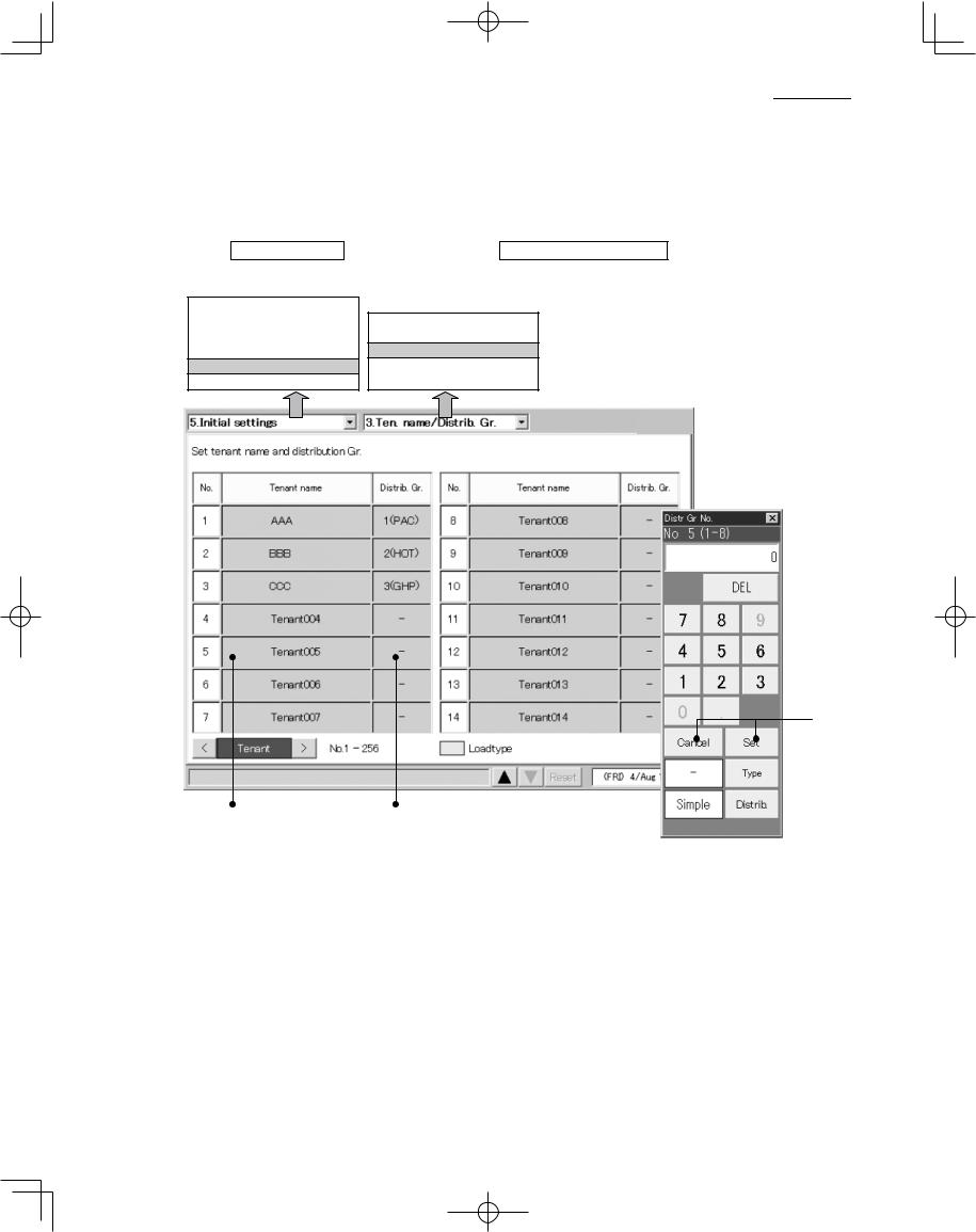
6.3.4 Setting tenant names and distribution groups
Use this screen to set tenant names and distribution groups.
You can also use this screen to set the product type (PAC, GHP, HOT, etc.) of indoor units.
Procedure
Select 5.Initial settings in the main menu and 3.Ten. name/Distrib. Gr. in the sub menu, then proceed as follows.
1.Status/Control 2.Total data/Cut-off 3.Distrib. ratio/Usage
4.Maintenance/Test Run
5.Initial settings
6.Auxiliary settings
1.Date/Distrib. 2.CNTR/Unit/Ten. No.
3.Ten. name/Distrib. Gr.
4.Pulse meter setting 5.Clear accum. data
 E
E

 C
C
A B 


 D
D
A Touch a tenant name. A keyboard window appears. Use the keyboard to enter the tenant name. Tenant names can be up to 20 characters long.
*See “7 ENTERING TEXT AND NUMBERS” for details about entering text on software keyboards.
*The tenant number range is from 1 to 256.
26
CZ-256ESMC1U_ .indb 26 |
2011/11/11 11:25:18 |
|
|
|
|
|
|
||
|
|
|
||
|
|
|
|
|

|
|
|
|
|
|
|
|
|
|
|
|
|
|
|
|
|
|
|
|
|
|
|
|
|
|
|
|
|
|
|
|
|
|
|
|
|
|
|
|
|
|
|
|
|
|
|
|
|
|
|
|
|
|
|
|
6 USING THE SYSTEM |
|
Main5Sub3 |
|
|
|
|
|||||||||||||||
|
|
|
|
|
|
|
|
|
|||||||||||||||||
|
|
|
|
|
|
|
|
|
|
|
|
|
|
|
|
|
|
|
|
|
|
|
|
|
|
B Touch a distribution group. A keyboard window like the one shown above appears. Use the keyboard to enter a distribution group number and to select the product type from among PAC, GHP and HOT.
Select “Simple” or “Load” in the distribution methods.
*Refer to “10. Calculating air conditioner distribution” for details.
The tenant set at “Load” distribution will have its “No” box display in light blue.
*The distribution group number range is from 1 to 8.
*This button is invalid when “No Distrib.” has been set. (Refer to Main5Sub1)
*The distribution group column set at loaded distribution has no product type such as “PAC” and “GHP” displayed.
*Make manual cut-off in advance to change the distribution method.
C Press the Type button to select “PAC” or “GHP” for the following unit that is unable to automatically recognize product type.
- Interface adaptor
This is only for “Simple distribution” setting.
D Specify which distribution method, “Simple” or “Load,” to apply to the selected distribution group.
E Touch Set to confirm the setting, or Cancel to cancel it.
 • PAC, GHP, and HOT cannot be mixed in the same group. Set up a separate distribution group for each
  type.
type.
•HOT multi units cannot be recognized automatically (they are recognized as PAC). Manually set the product type to HOT.
•HOT Tenants cannot be set at the “Load” distribution.
•“Load” distribution tenants cannot be set at “HOT”.
•Air conditioners unadaptable to loaded distribution cannot be set at “Load” Distribution.
•Interface adaptors are also unadaptable to loaded distribution.
27
CZ-256ESMC1U_ .indb 27 |
2011/11/11 11:25:19 |
|
|
|
|
|
|
||
|
|
|
||
|
|
|
|
|

|
|
|
|
|
|
|
|
|
|
|
|
|
|
|
|
|
|
|
|
|
|
|
|
|
|
|
|
|
|
|
|
|
|
|
|
|
|
|
|
|
|
|
|
|
|
|
|
|
|
|
|
|
|
|
|
6 USING THE SYSTEM |
|
Main5Sub4 |
|
|
|
|
|||||||||||||||
|
|
|
|
|
|
|
|
|
|||||||||||||||||
|
|
|
|
|
|
|
|
|
|
|
|
|
|
|
|
|
|
|
|
|
|
|
|
|
|
6.3.5 Making pulse meter settings
If you have connected pulse meters, use this screen to set the target distribution groups and the amount of electricity or gas per pulse.
Procedure
Select 5. Initial settings in the main menu, and 4. Pulse meter setting in the sub menu.
1.Status/Control 2.Total data/Cut-off 3.Distrib. ratio/Usage
4.Maintenance/Test Run
5.Initial settings
6.Auxiliary settings
1.Date/Distrib. 2.CNTR/Unit/Ten. No. 3.Ten. name/Distrib. Gr.
4.Pulse meter setting
5.Clear accum. data
 3
3
2 

1 |
5 |
4 |
6 |
7 |
A Select the pulse meter connection destination.
B You can change the type of pulse meter (power meter or gas meter). The above indicates the factory default state. When you touch the Meter type area, the Meter type window appears so that you can select the type of pulse meter to use.
C Touch a distribution group number. A numeric keypad appears for the distribution group. Use the keyboard to enter the distribution group number.
*The distribution group number range is from 1 to 8.
*The distribution group buttons are disabled when you have chosen not to perform distribution rate
calculations (see Main5Sub1).
D Touch the pulse unit amount column and enter the amount of electricity (kWh) or gas (m3) per pulse.
E If the product type is HOT Multi, select the unit for fuel metering.
28
CZ-256ESMC1U_ .indb 28 |
2011/11/11 11:25:19 |
|
|
|
|
|
|
||
|
|
|
||
|
|
|
|
|

|
|
|
|
|
|
|
|
|
|
|
|
|
|
|
|
|
|
|
|
|
|
|
|
|
|
|
|
|
|
|
|
|
|
|
|
|
|
|
|
|
|
|
|
|
|
|
|
|
|
|
|
|
|
6 USING THE SYSTEM |
|
Main5Sub4 |
|
|
|
|||||||||||||||
|
|
|
|
|
|
|
|
|||||||||||||||||
|
|
|
|
|
|
|
|
|
|
|
|
|
|
|
|
|
|
|
|
|
|
|
|
|
F Select this check box for ice heat accumulation night power meters. (Enabled during loaded distribution setting only.)
* This cannot be set for electricity meters configured for use with HOT Multi or simple distribution.
G For the night power meter set in F, select which outdoor system to meter ice heat accumulation by selecting the address.
29
CZ-256ESMC1U_ .indb 29 |
2011/11/11 11:25:20 |
|
|
|
|
|
|
||
|
|
|
||
|
|
|
|
|
 Loading...