


WJ-HD316
Table of contents
 Loading...
Digital Disk Recorders
−
+
TIMER
ERROR
ALARM
RESET
HDD 1
HDD 2
PULL
ALARM
ALARM
SUSPEND
OPERATE
Digital Disk Recorder
WJ-HD
316
M
ONITO
R1
MONITOR2
SHIFT
DISK SELECT
EL-ZOOM
COPY
TEXT
MARK
PAN/
TILT
ZOOM/
FOCUS
IRIS
LISTED
BUSY
A-B
REPEAT
PAN/TILT
SLOW
SETUP
/ESC
SEARCH
REV
FWD
SET
GOTO
LAST
PRESET
/AUTO
LOGOUT
OSD
SEQ
1
4
7
8
9
11
12
13
14
15
16
10/0
5
2
6
3
- REC STOP
REC-
STOP
PAUSE
PLAY
Operating Instructions
WJ-HD309
Model Nos. WJ-HD316
Before attempting to connect or operate this product,
please read these instructions carefully and save this manual for future use.
We declare under our sole responsibility that the product to which this
FUSE
declaration relates is in conformity with the standards or other normative
documents following the provisions of Directives EEC/73/23 and
EEC/89/336.
Wir erklären in alleiniger Verantwortung, daß das Produkt, auf das sich
diese Erklärung bezieht, mit der folgenden Normen oder normativen
Dokumenten übereinstimmt. Gemäß den Bestimmungen der Richtlinie
73/23/EEC und 89/336/EEC.
Nous déclarons sous note seule responsabilité que le produit auquel se
réfère la présente déclaration est conforme aux normes ou autres
documents normatifs conformément aux dispositions des directives
CEE/73/23 et CEE/89/336.
Nosotros declaramos bajo nuestra única responsabilidad que el producto
a que hace referencia esta declaración está conforme con las normas u
otros documentos normativos siguiendo las estipulaciones de las
directivas CEE/73/23 y CEE/89/336.
Noi dichiariamo sotto nostra esclusiva responsabilità che il prodotto a
cui si riferisce la presente dichiarazione risulta conforme ai seguenti
standard o altri documenti normativi conformi alle disposizioni delle
direttive CEE/73/23 e CEE/89/336.
WARNING:
• To prevent fire or electric shock hazard, do not expose this appliance to
rain or moisture. The apparatus shall not be exposed to dripping or
splashing and that no objects filled with liquids, such as vases, shall be
placed on the apparatus.
• All work related to the installation of this product should be made by
qualified service personnel or system installers.
CAUTION:
• Read the label on the rear of the unit for identification of this product,
and the power ratings.
CAUTION
RISK OF ELECTRIC SHOCK
DO NOT OPEN
CAUTION: TO REDUCE THE RISK OF ELECTRIC SHOCK,
DO NOT REMOVE COVER (OR BACK).
NO USER-SERVICEABLE PARTS INSIDE.
REFER SERVICING TO QUALIFIED SERVICE PERSONNEL.
The lightning flash with arrowhead symbol,
within an equilateral triangle, is intended to
alert the user to the presence of uninsulated
"dangerous voltage" within the product's
enclosure that may be of sufficient magnitude to constitute a risk of electric shock to
persons.
The exclamation point within an equilateral
triangle is intended to alert the user to the
presence of important operating and maintenance (servicing) instructions in the literature accompanying the appliance.
Power disconnection. Unit with or without
ON-OFF switches have power supplied to
the unit whenever the power cord is inserted
into the power source; however, the unit is
operational only when the ON-OFF switch is
in the ON position. The power cord is the
main power disconnect for all units.
Wij verklaren als enige aansprakelijke, dat het product waarop deze
verklaring betrekking heeft, voldoet aan de volgende normen of andere
normatieve documenten, overeenkomstig de bepalingen van Richtlijnen
73/23/EEC en 89/336/EEC.
Vi erklærer os eneansvarlige for, at dette produkt, som denne
deklaration omhandler, er i overensstemmelse med standarder eller
andre normative dokumenter i følge bestemmelserne i direktivene
73/23/EEC og 89/336/EEC.
Vi deklarerar härmed värt fulla ansvar för att den produkt till vilken
denna deklaration hänvisar är i överensstämmelse med
standarddokument, eller andra normativa dokument som framställs i
EEC-direktiv nr. 73/23 och 89/336.
Ilmoitamme yksinomaisella vastuullamme, että tuote, jota tämä ilmoitus
koskee, noudattaa seuraavia standardeja tai muita ohjeellisia asiakirjoja,
jotka noudattavat direktiivien 73/23/EEC ja 89/336/EE. säädöksiä.
Vi erklærer oss alene ansvarlige for at produktet som denne erklæringen
gjelder for, er i overensstemmelse med følgende normer eller andre
normgivende dokumenter som følger bestemmelsene i direktivene
73/23/EEC og 89/336/EEC.
For U.K.
FOR YOUR SAFETY PLEASE READ THE FOLLOWING TEXT CAREFULLY.
This appliance is supplied with a moulded three pin mains plug for your
safety and convenience.
A 5 amp fuse is fitted in this plug.
Should the fuse need to be replaced please ensure that the replacement
fuse has a rating of 5 amp and that it is approved by ASTA or BSI to
BS1362.
Check for the ASTA mark
fuse.
If the plug contains a removable fuse cover you must ensure that it is
refitted when the fuse is replaced.
If you lose the fuse cover the plug must not be used until a replacement
cover is obtained.
A replacement fuse cover can be purchased from your local Panasonic
Dealer.
IF THE FITTED MOULDED PLUG IS UNSUITABLE FOR THE SOCKET OUTLET IN YOUR HOME THEN THE FUSE SHOULD BE
REMOVED AND THE PLUG CUT OFF AND DISPOSED OF SAFELY.
THERE IS A DANGER OF SEVERE ELECTRICAL SHOCK IF THE
CUT OFF PLUG IS INSERTED INTO ANY 13 AMP SOCKET.
If a new plug is to be fitted please observe the wiring code as shown
below.
If in any doubt please consult a qualified electrician.
WARNING: This apparatus must be earthed.
The wires in this mains lead are coloured in accordance with the following code.
As the colours of the wire in the mains lead of this appliance may not
correspond with the coloured markings identifying the terminals in your
plug, proceed as follows.
The wire which is coloured green-and-yellow must be connected to
the terminal in the plug which is marked with the letter E or by the earth
symbol
The wire which is coloured blue must be connected to the terminal in
the plug which is marked with the letter N or coloured black.
The wire which is coloured brown must be connected to the terminal
in the plug which is marked with the letter L or coloured red.
How to replace the fuse
Open the fuse compartment with
a screwdriver and replace the fuse
and fuse cover.
Green-and-yellow: Earth
Blue: Neutral
Brown: Live
I or coloured green or green-and-yellow.
H or the BSI mark G on the body of the
IMPORTANT
The serial number of this product may be found on the rear
of the unit.
You should note the serial number of this unit in the space
provided and retain this book as a permanent record of your
purchase to aid identification in the event of theft.
Model No.
Serial No.
2

CONTENTS
PREFACE .................................................................... 4
FEATURES .................................................................. 4
PRECAUTIONS ........................................................... 5
TRADEMARKS AND REGISTERED
TRADEMARKS ............................................................ 6
LIMITATION OF LIABILITY ......................................... 6
MAJOR OPERATING CONTROLS AND
THEIR FUNCTIONS .................................................... 7
■ Front View ............................................................. 7
■ Rear View ............................................................. 9
■ On the Monitor 1 (To display only live image) ....... 10
■ On the Monitor 2
(To display live or recorded image) ....................... 11
STARTUP .................................................................... 15
CLOCK ADJUSTMENT ............................................... 16
SHUTDOWN ................................................................ 17
RECORDING (Manual Recording) .............................. 18
RECORDING (Emergency Recording) ........................ 20
PLAYBACK .................................................................. 21
PLAYBACK IMAGE ON A DESIGNATED DISK .......... 24
PLAYBACK FROM A DESIGNATED
TIME AND DATE ......................................................... 26
SEARCH AND PLAY ................................................... 27
■ Searching For a Recording Event and Playback
(Recording Event Search) ..................................... 27
■ Searching for a motion detected time and date from
recorded images and play it (VMD search) ........... 31
■ To delete the motion detection area ..................... 35
■ Searching for a marked point and play from that
point (Marking search) .......................................... 36
MONITOR LIVE IMAGES ............................................ 37
■ Displaying Live Images on a Single Screen .......... 37
■ Electronic Zoom .................................................... 37
■ Displaying on a Multi-screen ................................. 38
■ Sequential Display ................................................ 39
CONTROL CAMERAS ................................................ 40
■ Panning/Tilting ...................................................... 40
■ Zoom ..................................................................... 40
■ Focus .................................................................... 40
■ Iris ......................................................................... 41
■ Preset Action ......................................................... 41
■ Move a camera to the preset position ................... 42
■ Auto Function (Auto Pan, etc) ............................... 43
ABOUT THE EVENT FUNCTION ................................ 44
■ Action at an event occurrence .............................. 44
■ Alarm Function ...................................................... 45
■ Cancel the Alarm Action ....................................... 46
■ Suspend the Alarm Actions ................................... 46
COPYING (Duplicate) .................................................. 47
DELETE DATA ON THE DISK .................................... 49
■ Deletion of recorded images saved on the
hard disk manually ................................................ 49
FORMAT (INITIALIZE) A DVD-RAM DISK .................. 51
DISPLAY/EDIT TEXT INFORMATION ........................ 53
ERROR/WARNINGS ................................................... 55
OPERATION USING A SYSTEM CONTROLLER ...... 57
OPERATION USING A PC .......................................... 61
■ Features ................................................................ 61
■ System Requirements of a PC .............................. 61
INSTALLATION IN THE RACK ................................... 62
MANAGEMENT OF USERS/HOSTS .......................... 63
OPERATING THE UNIT FOR THE FIRST TIME ........ 65
Preparation for maintenance (HDD replacement,
installation, etc.) ........................................................... 66
CONNECTIONS .......................................................... 68
■ Connections when the unit is used
independently ........................................................ 68
■ Connections with an extension unit ...................... 69
■ Connections with DVD-RAM, CD-R, and
DVD-R drives ........................................................ 70
■ Connections with the VTR .................................... 71
■ Connections with PS·Data systems ...................... 72
■ Cascade connection of multiple units ................... 74
■ Connection with the RS485 camera ..................... 78
■ Mode Switch ......................................................... 80
■ RS485 Port ........................................................... 80
■ How to Use the Terminals of the ALARM/
CONTROL Connector ........................................... 81
■ How to Use the Terminals of the ALARM
Connector ............................................................. 85
■ How to Use the SERIAL Connector ...................... 87
SETUP ......................................................................... 88
■ Item list of the SETUP MENU ............................... 88
■ About the SETUP MENU ...................................... 90
■ Basic Operation with the SETUP MENU .............. 91
■ [Maintenance] Functions for Maintaining .............. 92
■ [Recording] ............................................................ 96
■ [Event] Function for Events ................................... 98
■ [Schedule] Settings for the recording/
event action schedule ......................................... 103
■ [Switcher] Settings for the switcher function ....... 108
■ [Display] .............................................................. 111
■ [Comm] Settings for communication with other
devices ................................................................ 114
■ [System] Settings on System .............................. 119
DISPLAY SETUP MENU OF CAMERA ..................... 125
DISK MANAGEMENT ................................................ 126
■ Notes on hard disk .............................................. 126
■ How to replace the built-in hard disk ................... 126
■ About the HDD DISK MENU ............................... 129
■ Display of the HDD DISK MENU ........................ 129
■ RAID 5 Function of the Extension Unit ............... 130
■ Formatting (Initialization) the Hard Disk .............. 131
■ Setting for Mirroring ............................................ 135
SERIAL (RS232C) CONNECTOR COMMAND
REFERENCE ............................................................. 139
■ SERIAL (RS232C) Communication Protocol ...... 139
■ Command Format ............................................... 139
FLOWCHART OF THE SETUP MENU ...................... 149
PARAMETERS AND THE DEFAULT SETTINGS
OF THE SETUP MENU ............................................. 150
TROUBLESHOOTING ............................................... 156
SPECIFICATION ....................................................... 160
STANDARD ACCESSORIES .................................... 161
3

PREFACE
The Digital Disk Recorders WJ-HD316/309 are designed for
use within a surveillance system and are a combination of a
hard disk recorder and a video multiplexer (16-input for the
WJ-HD316, 9-input for the WJ-HD309).
The digital hard disk recorder is a recording device using a
hard disk drive to record camera pictures instead of using
videotapes so that pictures recorded by repeated overwriting will not cause deterioration of the recorded picture quality. Up to 16 cameras can be connected to the WJ-HD316
FEATURES
Various Recording Functions
• Multi-Recording
It is possible to perform multiple recording using a single digital disk recorder even if the operating environments are different, for example, recording pictures of
cameras in different places at different times.
• Schedule recording
It is possible to perform recording automatically at a
scheduled time on a designated day of the week.
Schedules can be set on each camera.
directly (up to 9 cameras to the WJ-HD309) and it is possible to record their camera pictures. It is also possible to
display four or more camera pictures on a single monitor, to
switch camera pictures, and to operate cameras using this
unit.
Remote Operation via Network
It is possible to operate this unit using a PC connected to a
LAN (Local Area Network) or the Internet by the featured
network function.
Security Function and Reliability
• Authentication function (registration of ID and password) allows users access to a predetermined selection
of the available functions. Up to 32 users can be registered.
• Emergency Recording
In case of emergency, emergency recording will be
given a higher priority than other recording modes by
operating an external switch.
• External Timer Recording
It is possible to perform recording automatically using
an external timer.
• Event Recording
At an event occurrence, such as when an alarm signal
is supplied, the recording mode (quality and recording
rate) can be changed to high quality to record pictures.
• Motion Detection Function (VMD)
It is possible to start recording automatically when
motion is detected in a shooting area.
Frame Switcher Function
• It is possible to display pictures of four or more cameras on a single monitor (multi-screen) splitting the
monitor screen into 4, 7, 9, 10, 13, or 16 sections using
the WJ-HD316, and into 4, 7, or 9 sections using the
WJ-HD309.
While monitoring a multi-screen, each camera picture
will be displayed as a moving image.
• If alteration of a recorded image data is made for any
reason, the alteration alert function will announce it.
• If a hard disk crashes, the backup function
ing function
being any data loss.
*1
: Only when the recommended DVD-RAM drive, DVD-R
drive or CD-R drive is used
*2
: The mirroring function does not work with an external
hard disk drive such as an extension unit.
*3
: To use the RAID 5 function, an optional extension unit is
required.
*2
and the RAID 5 function*3prevent there
*1
, the mirror-
Transmission with Coaxial Cable, PS·Data and
RS485 Compatible
• It is possible to control a Panasonic combination camera such as the WV-CS850 using only a coaxial cable
but not other devices. Using a coaxial cable also compensates for transmission loss.
• It is easy to establish the surveillance system by connecting a PS·Data compatible system controller and
peripherals.
4

PRECAUTIONS
• Refer all work related to the installation of these
products to qualified service personnel or system
installers.
• Do not operate the appliances beyond their specified temperature, humidity, or power source ratings.
Use the appliance at temperatures within +5 °C +45 °C (41 °F - 133 °F) and humidity below 85 %.
The input power source for this appliance is 220 V 240 V AC 50 Hz.
•Handle the appliance with care.
Do not strike or shake, as this may damage the appliance.
• Do not strike or give a strong shock to the unit.
It may cause damage or allow water to enter the unit.
• Built-in backup battery
Before the first use, charge the built-in backup battery
by turning on the power for 48 hours or more.
If it is not charged enough, in a case where the power
goes down, the internal clock may keep bad time or the
operative condition may be different to that before the
electric power failure.
The built-in battery life is approximately 5 years. Ask the
shop where you purchased the unit when replacement
of the battery is required.
• Cooling Fan
Turn the power off when cleaning the unit. Otherwise it
may cause injuries.
Replacement costs of the cooling fan are not covered
by the warranty even if it needs to be done within the
warranty period. Consult your dealer for servicing.
•Cleaning
Turn the power off when cleaning the unit. Otherwise it
may cause injuries.
Hard disk drives are perishable. They will need to be
replaced after around 20 000 - 30 000 hours of operation in case they are used at temperature of 25 °C
(77 °F).
Replacement costs of the hard disk drives are not covered by the warranty even if it needs to be done within
the warranty period. Consult your dealer for servicing.
Set all the hard disk drives as master using the jumper
pin. Refer to the diagram attached on the HDD or the
operating instructions of the HDD for the jumper pin
assignment.
When hard disk drive trouble occurs, replace it immediately. Consult your dealer for servicing.
When replacing the hard disk drives, take notice that
the following.
Do not detach the hard disk drives or the cables connecting the unit and the front cover while the
HDD1/HDD2 indicators are lit or for around 30 seconds
after the indicators go off.
Protect the hard disk drives from static electricity.
Do not stack them, or keep them upright.
Do not use an electric screwdriver to fix them.
(Tightening torque: Approx. 0.49 N · m (5 k
Avoid rapid changes of the temperature/humidity to
prevent condensation. (Acceptable change: within
15 °C/h (59 °F/h))
• Indication label
Refer to the indication labels placed on the top and buttom of the unit as to the indications of equipment classification and power source, etc.
• Avoid placing receptacles that contain liquids such as
water near the unit.
If liquid spills onto the unit, it may cause fire or an electric shock.
• Do not expose the unit to water or moisture, or try to
operate it in wet areas.
gf · cm))
Do not use strong or abrasive detergents when cleaning the appliance body.
Use a dry cloth to clean the appliance when it is dirty.
When the dirt is hard to remove, use a mild detergent
and wipe gently.
• Built-in hard disk drives
Hard disk drives are vulnerable to vibration. Handle
them with care.
It is possible to damage them if they are moved while
their motors are still running. Do not move them just
after turning the power of them on or off (for around 30
seconds).
• Prevent condensation from forming on the surface of
the hard disk.
Wait until the dew evaporates in any of the following
cases.
The recorder is moved to a place significantly different
in temperature or humidity.
The recorder is moved out of an air-conditioned room.
The recorder is placed in an extremely humid place.
The recorder is placed in a room where a heater has
just been turned on.
• We recommend that you make a note of your settings
and save them. This will help when you are required to
change the system configuration, or when unexpected
trouble or failure occurs.
5

TRADEMARKS AND REGISTERED TRADEMARKS
• Adobe, Adobe logos, and Acrobat are registered trademarks of Adobe Systems Incorporated in the U.S. and/
or other countries.
• Microsoft, Windows and Windows XP are registered
trademarks of Microsoft Corporation in the U.S. and/or
other countries.
• Other names of companies and products contained in
these operating instructions may be trademarks or registered trademarks of their respective owners.
• Distributing, copying, disassembling, reverse compiling, reverse engineering, and also exporting in violation
of export laws of the software provided with this product, is expressly prohibited.
About These Operating Instructions
There are 3 operating instructions for the WJ-HD316/WJHD309 as follows.
• Operating Instructions (book, these operating instructions)
• Network Operating Instructions (PDF)
• Network Setup Instructions (PDF)
These "Operating Instructions" contain descriptions of how
to operate this unit with the buttons on the front panel.
Refer to the "Network Operating Instructions" on the provided CD-ROM for descriptions of how to operate this unit
from a PC.
Refer to the "Network Setup Instructions" on the provided
CD-ROM for descriptions of how to perform the required
settings and how to connect to other devices.
®
Adobe
tions (PDF) on the provided CD-ROM. When the Adobe
Reader is not installed on the PC, download the latest
Adobe
Reader is required to read these operating instruc-
®
Reader from the Adobe web site and install it.
®
LIMITATION OF LIABILITY
IN NO EVENT SHALL MATSUSHITA ELECTRIC INDUSTRIAL CO., LTD. BE LIABLE TO ANY PARTY OR ANY PERSON, EXCEPT FOR REPLACEMENT OR REASONABLE
MAINTENANCE OF THE PRODUCT, FOR THE CASES,
INCLUDING BUT NOT LIMITED TO BELOW:
(1) ANY DAMAGE AND LOSS, INCLUDING WITHOUT LIM-
ITATION, DIRECT OR INDIRECT, SPECIAL, CONSEQUENTIAL OR EXEMPLARY, ARISING OUT OF OR
RELATING TO THE PRODUCT;
(2) PERSONAL INJURY OR ANY DAMAGE CAUSED BY
INAPPROPRIATE USE OR NEGLIGENT OPERATION
OF THE USER;
(3) UNAUTHORIZED DISASSEMBLE, REPAIR OR MODIFI-
CATION OF THE PRODUCT BY THE USER;
(4) ANY PROBLEM, CONSEQUENTIAL INCONVENIENCE,
OR LOSS OR DAMAGE, ARISING OUT OF THE SYSTEM COMBINED BY THE DEVICES OF THIRD PARTY.
6

MAJOR OPERATING CONTROLS AND THEIR FUNCTIONS
S-VIDEO
COPY 2
VIDEO
OUT
AUDIO
OUT
S-VIDEO
COPY 2
VIDEO
OUT
AUDIO
OUT
[WJ-HD309]
[WJ-HD316]
ALARM
TIMER
HDD 2
ERROR
HDD 1
ALARM
SUSPEND
ALARM
RESET
OPERATE
MONITOR1
MONITOR2
1
5
9
13
2
6
10/0
14
3
7
11
15
4
8
12
16
SEQSHIFT OSD
PAN/
TILT
STOP
PLAY PAUSE
REC
-
REC STOP
ZOOM/
FOCUS
TEXT
COPY
DISK SELECT
EL-ZOOM
MARK
LOGOUT
IRIS
PRESET
/AUTO
A-B
REPEAT
GOTO
LAST
LISTED
SEARCH
BUSY
SETUP
/ESC
SET
REV
–+
FWD
PULL
Digital Disk Recorder
WJ-HD
PAN/TILT
SLOW
LOGOUT
ALARM
TIMER
HDD 2
ERROR
HDD 1
ALARM
SUSPEND
ALARM
RESET
OPERATE
MONITOR1
MONITOR2
1
4
7
2
5
8
0
3
6
9
TEXTSEQSHIFT OSD
ZOOM/
FOCUS
COPY
DISK SELECT
EL-ZOOM
MARK
IRIS
PRESET
/AUTO
A-B
REPEAT
GOTO
LAST
LISTED
SEARCH
BUSY
SETUP
/ESC
SET
REV
–+
FWD
PULL
Digital Disk Recorder
WJ-HD
STOP
PLAY PAUSE
REC
-
REC STOP
PAN/TILT
SLOW
PAN/
TILT
qw e rtyu i
o !8 !9 @0
!0 !1
!3 !4 @1 @2 @3
@4 @5 #0
!2
!5 !6 !7 @6 @7 @8 @9
qw e rtyu i
o !8 !9 @0
!0 !1
!3!4 @1 @2 @3
@4 @5 #0
!2
!5 !6 !7 @6 @7 @8 @9
■ Front View
q Operate Indicator (OPERATE)
Lights up when the power is turned on.
w Alarm Suspension Indicator (ALARM SUSPEND)
Lights up when the alarm suspension mode is selected.
e Alarm Indicator (ALARM)
Blinks when an alarm occurs, and lights steadily when
the activated alarm is reset automatically.
To turn this indicator off, press the ALARM RESET button.
r Alarm Reset Button (ALARM RESET)
Pressing this button cancels alarm activation, and
returns the system to the condition before the alarm
was activated.
t Error indicator (ERROR)
Blinks orange when an error occurs that will not keep
the unit from running.
Blinks red when an error occurs that may cause the
system to go down.
Refer to page 55 for further information about
error/warnings.
y Timer Indicator (TIMER)
Lights up when the schedule recording is set, and
blinks while the schedule recording is being performed.
u HDD Access Indicators (HDD1/HDD2)
Blinks when the HDD1 or the HDD2 is accessed
respectively.
i Monitor Switch button (MONITOR1/MONITOR2)
Pressing this button switches the monitor. This button
lights up when monitor 1 is selected, and goes off when
monitor 2 or the VGA monitor is selected.
o Shift Button (SHIFT)
Toggles the functions of the camera selection buttons.
!0 Camera Selection Buttons ([1] - [10/0], [11] - [16] for
the WJ-HD316, [1] - [9], [0] for the WJ-HD309)
Pressing a button displays live or playback images of
the selected camera. The LED in the button indicates
the status as follows.
Green: When a button is lit green, the currently dis-
played image on the monitor is live from a respective camera.
Orange: When a button is lit orange, the image from a
respective camera is recorded.
Blue: When a button is lit blue, the currently displayed
image on the monitor is live from a respective camera and is also recorded.
7

When the shift button is lit, these buttons work as the
toggled function buttons.
(The buttons available as the toggled function buttons
will light green when the shift button is lit.)
!1 Pan, Tilt, Latest Recorded Image Playback Button
(PAN/TILT, GO TO LAST)
Pans/tilts a selected camera, or plays back the latest
recorded image.
(Refer to page 40 and 22 respectively.)
@3 Set Button (SET)
Works differently depending on the situations listed
below:
• Plays recorded images at the current playback speed
when this button is pressed during fast playback.
• Registers preset positions of cameras.
• Activates the auto focus function.
• Sets the alarm suspension mode on/off.
• Determines the setting of parameters on the setup
menus.
!2 Zoom, Focus, A - B Repeat Button (ZOOM/FOCUS,
A-B REPEAT)
Zooms in/out, adjusts focus, or repeats playback of
recorded images between two designated points.
(Refer to page 40 and 23 respectively.)
!3 Iris, Listing Button (IRIS, LISTED)
Adjusts iris, or enables/disables the filtering playback.
(Refer to page 41 and 27 respectively.)
!4 Preset, Auto Pan Button (PRESET/AUTO)
Moves a camera to the preset position, or activates the
auto function.
(Refer to page 41 and 43 respectively.)
!5 Stop Button (STOP)
Stops playback.
!6 Play/Pause Button (PLAY/PAUSE)
Plays recorded images, or pauses playback.
!7 Record Button (REC/REC STOP)
Starts recording. To stop recording, press this button
down for 2 seconds or more.
!8 Slow Button (SLOW)
Pans/tilts a selected camera slowly.
!9 Search Button (SEARCH)
Displays the searching menu.
@0 Setup, Escape Button (SETUP/ESC)
Displays the setup menu, or turns back to a previous
page of the setup menu, etc.
@1 Busy Indicator (BUSY)
Lights when a selected camera was not available to
operate because another user is operating it using a
controller or a PC via a network. In this case, wait until
this indicator goes off.
@2 Arrow Buttons (CDAB)
Adjusts zooming/focus, or moves the cursor on the
setup menus and the searching menu.
@4 Jog Dial
Works differently depending on the situations as follows:
• Plays recorded images frame by frame when this dial is
rotated during pausing playback.
• Skips playback time when this dial is rotated during
playback at normal speed.
• Moves the cursor on the searching menu or the thumbnail menu.
• Selects a parameter setting or a character on the setup
menus.
@5 Shuttle Ring
Works differently depending on the situations as follows:
• Plays fast when this dial is rotated during playback at
normal speed.
• Turns the searching menu pages or the thumbnail
menu pages.
@6 Connectors Cover
@7 Copy Port (COPY2)
Connect a recommended DVD-RAM drive, CD-R drive
or DVD-R drive with this port.
@8 S-Video Output Connector (S-VIDEO)
Connect the S-video input connector of a VTR with this
connector. The same video signal supplied to the MONITOR OUT2 connector on the rear panel will be supplied to this connector.
@9 Video Output Connector (VIDEO OUT)
Connect the video input connector of a VTR with this
connector. The same video signal supplied to the MONITOR OUT2 connector on the rear panel will be supplied to this connector.
#0 Audio Output Connector (AUDIO OUT)
This connector, for an RCA standard jack, supplies an
unbalanced –10 dBV, 600 Ω line output audio signal to
an external device.
Recorded audio will be supplied from this connector
during playback.
The same audio signal supplied to the AUDIO OUT
connector on the rear panel will be supplied to this connector.
8

■ Rear View
[WJ-HD309]
[WJ-HD316]
IN
OUT
CASCADE
OUT
3
2
1
99887766554433221
1
12
VIDEO
AUDIO IN AUDIO OUT
MONITOR OUT CASCADE IN
MONITOR (VGA) ALARM/CONTOROL
SERIAL ALARM
POWER
COPY 1
MODE
EXT STORAGE10/100BASE-TRS485(CAMERA)
DATA
AC IN
SIGNAL GND
1
4 2
12
IN
OUT
CASCADE
OUT
16
16
3
1515141413
2
1
13
12121111101099887766554433221
1
VIDEO
AUDIO IN AUDIO OUT
MONITOR OUT CASCADE IN
MONITOR (VGA) ALARM/CONTOROL
SERIAL ALARM
POWER
COPY 1
MODE
EXT STORAGE10/100BASE-TRS485(CAMERA)
DATA
AC IN
SIGNAL GND
1
4 2
w t y u i
o !0 !1 !3 !5 !8
!2 !4 !6 !7e
r !9
w t y u i
o !0 !1 !3 !5 !8
!2 !4 !6 !7q e
r !9
q
q Audio Input Connectors (AUDIO IN 1 - 4)
These connectors, for RCA pin jacks, accept an unbalanced –10 dBV, 10 kΩ line input audio signal supplied
from an external device such as a microphone amplifier.
w Audio Output Connector (AUDIO OUT)
This connector, for an RCA standard jack, supplies an
unbalanced –10 dBV, 600 Ω line output audio signal to
an external device.
Recorded audio will be supplied from this connector
during playback.
e Video Input Connectors (CAMERA IN 1 - 16 for the
WJ-HD316/CAMERA IN 1 - 9 for the WJ-HD309)
Connect system cameras or combination cameras to
these BNC connectors.
A 75 Ω termination is made unless the video output terminal is connected.
To connect combination cameras, connect them to the
CAMERA IN 1 - 8 connectors of the WJ-HD316, or the
CAMERA IN 1 - 6 of the WJ-HD309 (accept coaxial
communication).
r Video Output Connectors (CAMERA OUT 1 - 16 for
the WJ-HD316/CAMERA OUT 1 - 9 for the WJ-HD309)
These BNC connectors supply video signals looped
through the video input connectors.
Note: Video signals will not be supplied from the CAM-
ERA OUT 1 - 8 connectors (CAMERA OUT 1 - 6
connectors for the WJ-HD309) if the power of the
unit is off.
t Monitor Output Connector (MONITOR OUT1, MONI-
TOR OUT2/CASCADE OUT)
Connect monitors to these BNC connectors.
The MONITOR OUT2 connector can also be used as
the CASCADE OUT connector.
When using two or more units of the WJ-HD316/WJHD309 and using the MONITOR OUT2 connector as
the CASCADE OUT connector, connect with the CASCADE IN connector of another WJ-HD316/WJ-HD309.
y Cascade In Connector (CASCADE IN)
Connect with the CASCADE OUT connector of another
WJ-HD316/WJ-HD309 when using two or more units of
the WJ-HD316/WJ-HD309.
u Serial Connector (SERIAL)
Connect a PC with this D-Sub 9-pin connector when
controlling this unit.
i Monitor Connector (MONITOR (VGA))
Connect a VGA monitor with this connector. The same
video signal supplied to the MONITOR OUT2 connector
will be supplied to this connector.
IMPORTANT
For European Customers
Some VGA monitors in Europe cannot be used simultaneously with television display. When you enable television
display in Europe, the refresh rate for the monitor and television is set to 50 Hz. Some VGA monitors may not support
this refresh rate and could be damaged.
9

Please check the documentation supplied with your monitor
to see if your VGA monitor supports a refresh rate of 50 Hz.
If your VGA monitor does not support 50 Hz (or if you are
not sure), then turn off your VGA monitor before turning on
WJ-HD316/WJ-HD309 when using your television as a display.
o Alarm Connector (ALARM)
Connect an external device such as a sensor or a door
switch with this D-Sub 25-pin connector.
!0 Alarm/Control Connector (ALARM/CONTROL)
Connect a control switch with this D-Sub 25-pin connector when controlling this unit using an external
device, or when controlling an alarm device such as a
buzzer or a lamp.
!1 PS·Data Ports (DATA)
Connect PS·Data compatible devices with these ports.
!2 Mode Switches (MODE)
Set the operation mode of this unit with these dip
switches.
!3 RS485 Ports (RS485 (CAMERA))
Connect RS485 compatible combination cameras with
these ports.
!4 Network Port (10/100BASE-T)
Connect this unit to a network compatible with 10BASET or 100BASE-Tx when controlling this unit using a PC
via a network.
■ On the Monitor 1 (To display
only live image)
q
q
q
Important:
• The SETUP MENU cannot be displayed on the monitor
1.
• It will take around 2 minutes to display live image on the
monitor 1 after turning on the power of the unit.
1. Camera Title
Displays the edited camera title.
A position to display a camera title can be selected
from the following.
Upper left, upper right, lower left, lower right, centre
The default camera title position is lower right (RLOWER).
Note: The camera title will be displayed with 16 charac-
ters (2 lines: 8 characters per line).
q
wewe
q
wewe
!5 Copy Port (COPY1)
Connect a recommended DVD-RAM drive, CD-R drive
or DVD-R drive with this port.
!6 Extra Storage Port (EXT STORAGE)
Connect an optional extension unit (WJ-HDE300) with
this port.
!7 Power Switch (POWER)
Turns the power of this unit on and off.
!8 Signal Ground Terminal (SIGNAL GND)
!9 Power Cord Inlet (AC IN)
Connect the power cord to this inlet.
2. Time
Displays the current time (hour:minute:second) and
date (day:month:year).
A position to display the time can be selected from the
following.
Centre, upper left, lower left, upper right, lower right
The default time display position is lower left (LLOWER).
Note: When the camera title and the time display are
layered, only the time display will be displayed.
3. Alarm Display
When an alarm has occurred, an alarm display will be
displayed.
The alarm display will be displayed differently as follows depending on which alarm has occurred.
VMD-*: When motion is detected.
LOSS-*: When video loss has occurred.
COM-#: When a command alarm has occurred.
TRM-#: When a terminal alarm has occurred.
*: Camera number (1 - 16 for the WJ-HD316, 1 - 9 for
the WJ-HD309)
#: Event number
10
Note: Refer to page 44 for further information about
event types and event actions.
■ On the Monitor 2 (To display live
or recorded image)
q
w
–
C
w
B
q
–
q
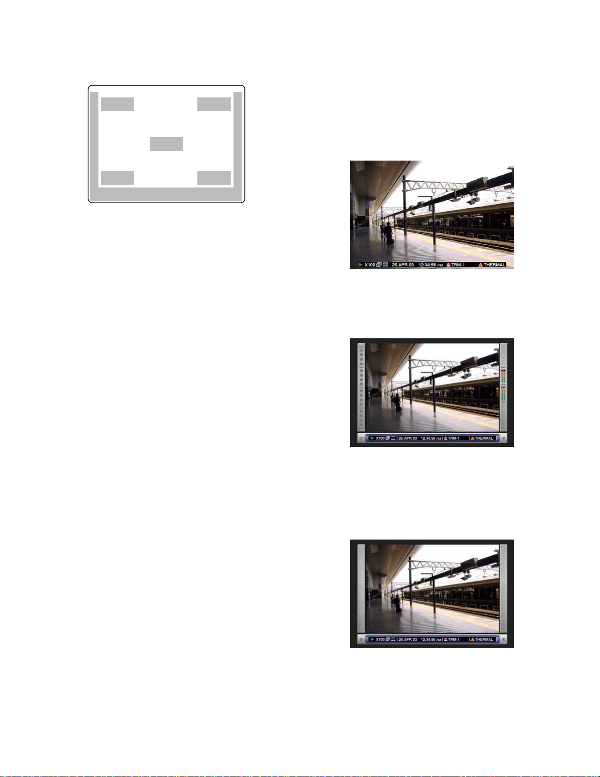
2. Task Bar
Displays the current status.
The task bar consists of the main bar (
bar (
w - B), and the right bar (w - C).
There are 3 different ways to display the task bar as follows.
Mode 1
Displays only the main bar and the status is displayed
on it.
w - A), the left
q
q
w – A
Notes:
• Same images displayed on monitor 2 will be displayed
on the VGA monitor.
• The camera title will be displayed with 16 characters (2
lines: 8 characters per line).
Important:
• Since the VGA output from this unit is the same as for
televisions (720 H x 576 V pixels/vertical frequency of
50 Hz), it may be possible that both the left and right
edges can not be fit onto the screen depending on the
VGA monitor.
• It is impossible to use the MONITOR (VGA) connector
when connecting the unit in the cascade connection.
• It may take time to display live image on the VGA monitor if the VGA monitor is turned on/off during the unit is
running.
IMPORTANT
For European Customers
Some VGA monitors in Europe cannot be used simultaneously with television display. When you enable television
display in Europe, the refresh rate for the monitor and television is set to 50Hz. Some VGA monitors may not support
this refresh rate and could be damaged.
• Please check the documentation supplied with your
monitor to see if your VGA monitor supports a refresh
rate of 50 Hz.
If your VGA monitor does not support 50 Hz (or if you
are not sure), then turn off your VGA monitor before
turning on WJ-HD316/WJ-HD309 when using your television as a display.
Mode 2
Displays the status on the main bar, the left bar and the
right bar.
Mode 3
Displays the status only on the main bar, and does not
display information on the left bar and the right bar.
Note: Mode 2 and Mode 3 are graphic images. They
may not be as clear as Mode 1.
1. Camera Title
Displays the edited camera title.
A position to display a camera title can be selected
from the following.
Upper left, upper right, lower left, lower right, centre
The default camera title position is lower right (RLOWER).
11

● Status on the Task Bar
q Status Display Area
w Copy/Delete Icons
e Live/Playback Time Display Area
r Alarm Display Area
t Error Display Area
• On the Main Bar
q Status Display Area
Indicated Item Status Indication
Live
Playback
Recording
Search Indicates that searching is currently being performed
w Copy/Delete Icons
Indicated Item Status Indication
Copy Indicates that data copy is currently being performed
Delete
Indicates live image display status
Indicates that playback is currently being performed
with the displayed playback speed
Indicates that recording is currently being performed
Indicates that data deletion is currently being performed
: Live image is displayed
: Live images are displayed
sequentially
5: Currently playing
4: Currently playing in reverse
h: Currently pausing
2 : Currently playing at fast speed
1 : Currently playing in reverse at fast
speed
: Currently recording
: Currently searching
: Currently copying
: Currently deleting data
e Live/Playback Time Display Area
Indicated Item Status Indication
Time Displays time of the displayed image
12
When displaying live image: Current time
When playing recorded image: Time when
recorded
*: During summer time, an asterisk (*) will be dis-
played on the left side of the displayed time.
Year:Month:Day Hour:Minute:Second
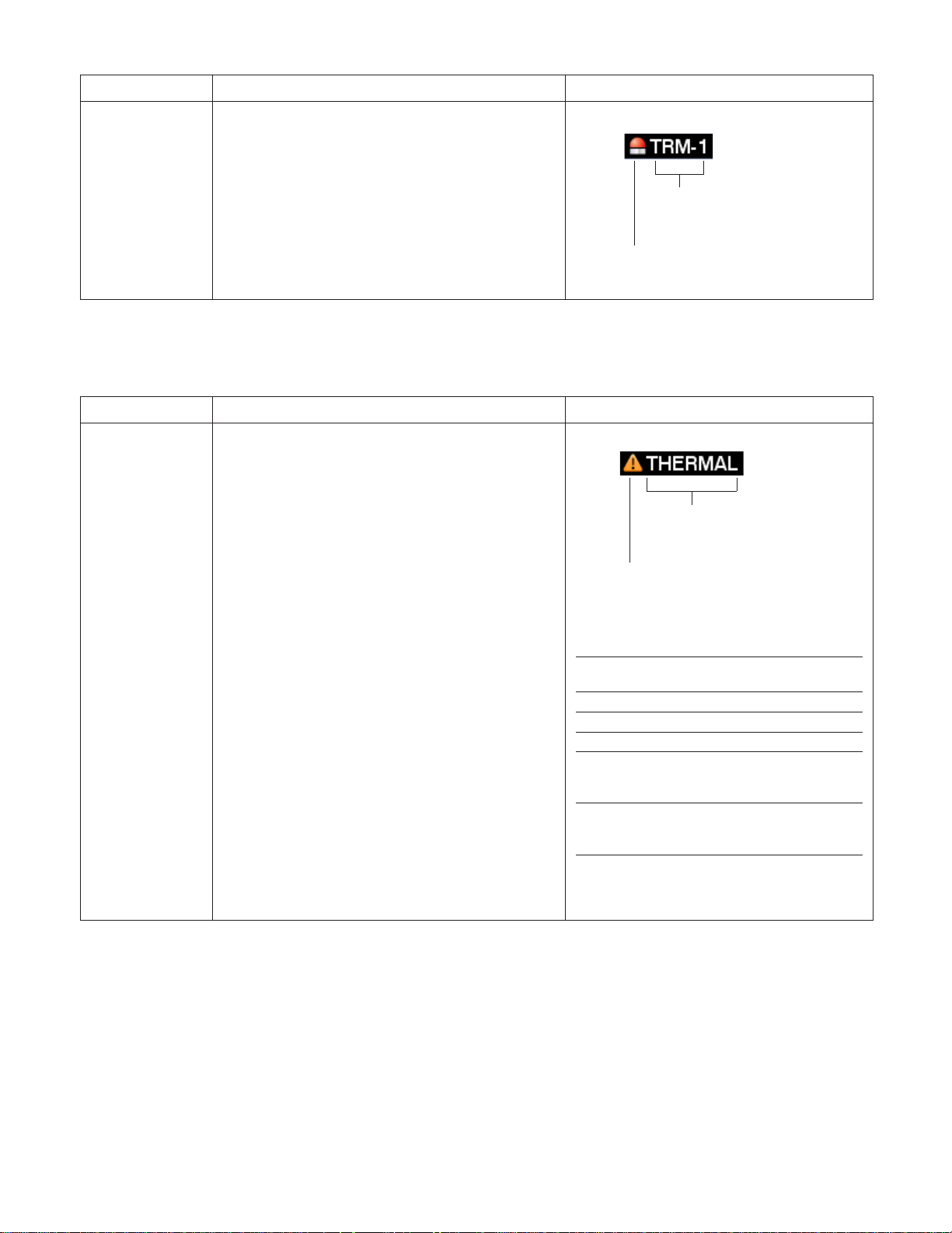
r Alarm Display Area
Indicated Item Status Indication
Alarm Indicates that an alarm has occurred
VMD-*: When motion is detected
LOSS-*: When video loss has occurred
COM-*: When a command alarm has occurred
TRM-*: When a terminal alarm has occurred
*: Camera number (1 - 16 for the WJ-HD316, 1 - 9 for
the WJ-HD309)
#: Alarm number
Note: Refer to page 44 for further information about event types and event actions.
t Error Display Area
Indicated Item Status Indication
Error Warning Indicates an error occurrence or warning
ALT-*: Alteration is detected
W-ERROR: Failed to write data on the HDD
SMART: Warning of the HDD malfunction
H-METER: Set time for hour-meter (active time of
the HDD) warning has passed
THERMAL: The temperature inside the unit is too
high
POWER: A power outage has been detected
#-nn%: Warning about running out of disk space
while displaying available disk space percentage
#-FULL: No available disk space
MEDIUM-n: An error occurred in an external
recording device
REMOVE: The hard disk is removed from the sys-
tem automatically because of an access error
FAN: The fan is faulty
*: Camera number (1 - 16 for the WJ-HD316, 1 - 9
for the WJ-HD309)
#: Abbreviation that indicates partition
nn: Available disk size
n: Number of connector that an external recording
device is connected to
Abbreviation of partition
Status Displayed
Normal recording area NML
Event recording area EVT
Copy area CPY
External recording device
connected to the COPY1 port
on the rear panel CP1
External recording device
connected to the COPY2 port
on the front panel CP2
Alarm type
Alarm is occurring currently
Error type
Error is occurring currently
abbreviation
Note: Refer to page 55 for further information about error types and what to do when an error has occurred.
13

• On the Left Bar
Indicated Item
Camera Indicates recording and displaying status
Grey: Camera currently not displayed or not con-
nected to a respective channel
Green: Camera displayed on the monitor
Orange: Camera currently being recorded
Blue: Camera currently being recorded and dis-
played on the monitor
Status Indication
• On the Right Bar
Indicated Item
Used disk space
Indicates the available disk space of each partition.
Top: 100 % of the disk space is used (no avail-
able disk space)
Second from the top: 80 % of the disk space is
used
Centre: 60 % of the disk space is used
Second from the bottom: 40 % of the disk space
is used
Bottom: 20 % of the disk space is used
Note: When "CONTINUE" is selected on the
"Termination" page of the "Maintenance" setup
menu, available disk space will not be displayed.
Refer to a system administrator for further information.
Status Indication
Camera 1 is on the top and camera
16 is on the bottom
Normal Recording Area
Event Recording Area
NML: Available disk space of the normal record-
ing area used for manual recording and
schedule recording
EVT: Available disk space of the event recording
area used for event recording and emergency
recording
14

STARTUP
z Insert the power plug to an outlet (AC 220 V -
240 V, 50 Hz)
Note: Make sure the power source is AC 220 V - 240 V,
50 Hz.
x Turn on the power switch on the rear panel.
The OPERATE indicator will light and the system check
(checking the system and hard disk) will start.
The startup splash image below will be displayed on monitor 2 and the VGA monitor during the system check.
When the auto login is off, the login window will be displayed if any button on the front panel of this unit is pressed
after the system check. (Go to step 3)
When the auto login is on, live images will be displayed
after the system check.
c Enter a user name and password.
Rotate the jog dial to select a character to be entered in the
cursor position.
It is also possible to enter numbers by pressing the camera
selection buttons ([1] - [10/0] for the WJ-HD316, [1] - [9],
[0] for the WJ-HD309).
To move the cursor, press the arrow buttons.
Use the same method to enter or edit characters attached
to images. Refer to page 53 for further information.
Notes:
• The default user name and password are as follows:
User name: ADMIN
Password: 12345
• To enhance the security, change the password for an
administrator before start running the unit. It is recommended to change the password for an administrator
periodically.
Notes:
• If the hard disk configuration had been changed after
the last startup or the hard disk has problems, the HDD
DISK MENU will be displayed automatically after the
startup splash. (Refer to page 129 for further information.)
• It is possible to display the disk configuration menu by
pressing the SET button when the image below that
says the system check has been completed is displayed.
Important:
When using the optional extension unit (WJ-HDE300),
turn the power of this unit after turning on the power of
all extension units.
v Display a live image.
Press the SET button to display a live image.
If the authentication (login) window is displayed, enter user
name and password.
When authenticated, a live image will be displayed.
When not authenticated, the authentication (login) window
will be displayed again.
15
CLOCK ADJUSTMENT
316
It is recommended to check the clock periodically and put
the clock right if it shows the wrong time.
Adjust the clock when displaying a live image.
zn
STOP
PLAY PAUSE
REC
-
SEARCH
SETUP
/ESC
REC STOP
SET
–
REV FWD
+
MONITOR1
MONITOR2
SHIFT SEQ
DISK SELECT
EL-ZOOM
2
1
5
6
COPY
9
10/0
1413
3
7
TEXT
11
LOGOUT
15 16
OSD
MARK
LOGOUT
4
8
12
PAN/
TILT
ZOOM/
FOCUS
IRIS
PRESET
/AUTO
GOTO
LAST
A-B
REPEAT
LISTED
PAN/TILT
SLOW
BUSY
cb vxcv
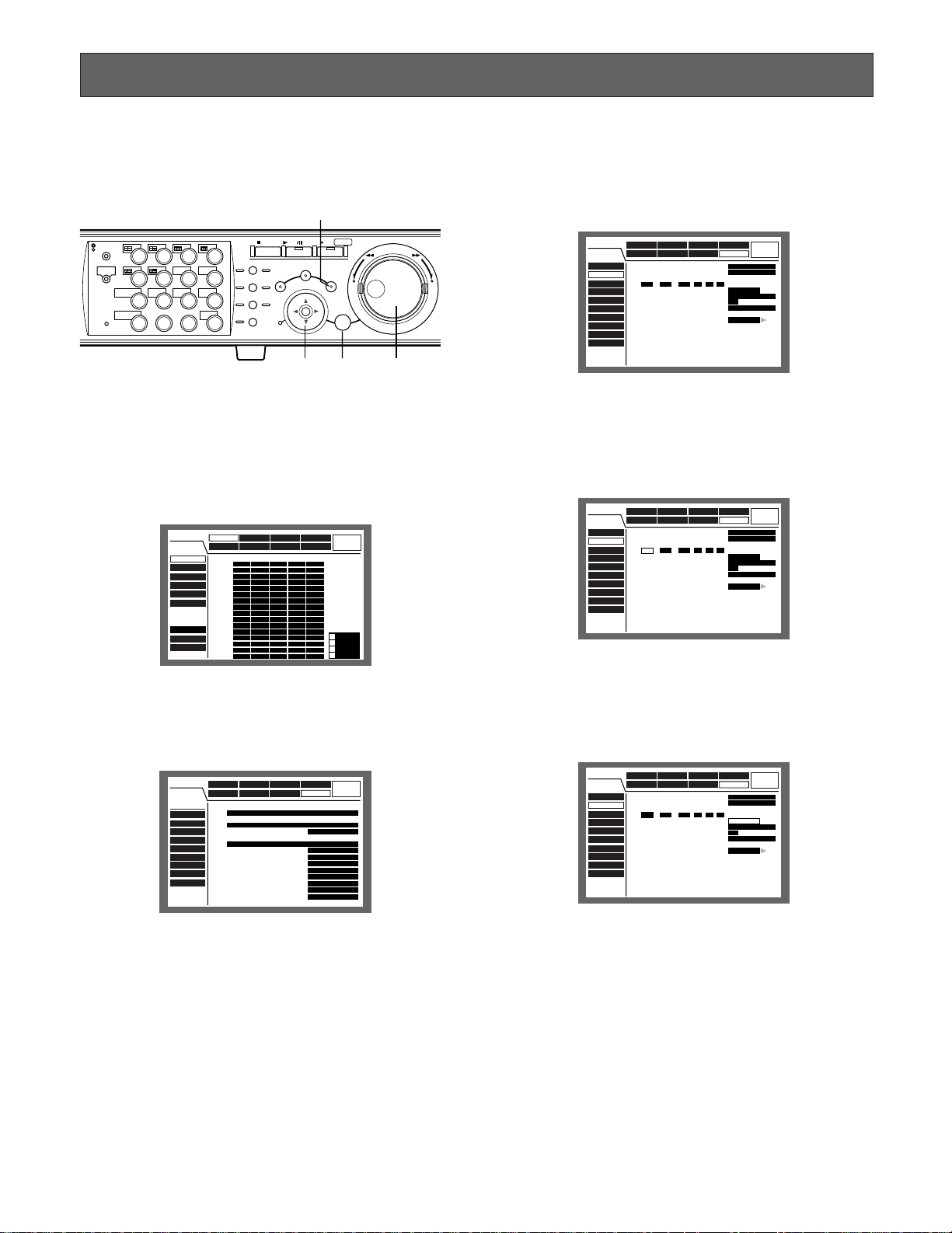
z Press the SETUP/ESC button for 2 seconds or
more.
The SETUP MENU will be displayed on monitor 2 and the
VGA monitor.
SET UP MENU
REC Rate
Disk Info
Version Info
Disk End Mode
Disk Capacity
Date Delete
Event Log
Error Log
Access Log
Recording Event Schedule
Maintenance
Display CommSwitcher
MANU SCHE
CAM 1
AUTO
CAM 2
AUTO
CAM 3
AUTO
CAM 4
AUTO
CAM 5
AUTO
CAM 6
AUTO
CAM 7
AUTO
CAM 8
AUTO
CAM 9
AUTO
CAM 10
AUTO
CAM 11
AUTO
CAM 12
AUTO
CAM 13
AUTO
CAM 14
AUTO
CAM 15
AUTO
CAM 16
AUTO
LIVE
System
POST EVT
EMR
PRE EVT
1ips
1ips
1ips
1ips
1ips
1ips
1ips
1ips
1ips
1ips
1ips
1ips
1ips
1ips
1ips
1ips
1ips
1ips
1ips
1ips
1ips
1ips
1ips
1ips
1ips
1ips
1ips
1ips
1ips
1ips
1ips
1ips
1ips
1ips
1ips
1ips
1ips
1ips
1ips
1ips
1ips
1ips
1ips
1ips
1ips
1ips
1ips
1ips
1ips
1ips
1ips
1ips
1ips
1ips
1ips
1ips
SUPER FINE
1ips
1ips
FINE
1ips
1ips
NORMAL
1ips
1ips
EXTENDED
1ips
1ips
c Move the cursor to "Time & Date" using the
arrows button (CD), and press the SET but-
ton.
The "Time & Date" menu will be displayed.
SETUP MENU
Basic Setup
Time & Date
User Regist.
User Edit
User Delete
Host Regist.
Host Edit
Host Delete
User Level
Save/Load
Maintenance Recording Event
Switcher
Display
Date Format
■
Time Format
■
Time & Date
■
..:
1 03 12 00 00
JAN
Auto Adjust Time
■
Master Time
Summer Time(Day Light Saving)
■
Summer Time(Day Light Saving)Table
■
Schedule
LIVE
System
Comm
DD.MMM.YY
12H
AM
SET
OFF
12 :00 AM
AUTO
SETUP
v Move the cursor to "Time Format" using the
arrows button and set the time (Month, Day,
Year, Time) using the jog dial.
SETUP MENU
Basic Setup
Time & Date
User Regist.
User Edit
User Delete
Host Regist.
Host Edit
Host Delete
User Level
Save/Load
Maintenance Recording Event
Switcher
Display
Date Format
■
Time Format
■
Time & Date
■
1. . 03JAN 12 00 00
Auto Adjust Time
■
Master Time
Summer Time(Day Light Saving)
■
Summer Time(Day Light Saving)Table
■
Comm
::
Schedule
System
DD.MMM.YY
12H
AM
OFF
12 :00 AM
AUTO
SETUP
LIVE
SET
x Move the cursor to "System" using the arrows
button (CDAB) and press the SET button.
SETUP MENU
Basic Setup
Time & Date
User Regist.
User Edit
User Delete
Host Regist.
Host Edit
Host Delete
User Level
Save/Load
Maintenance Recording Event
Switcher
Display
ADMIN Password
■
*****
PSD User
■
ADMIN
Auto Login
■
Auto Login User
ADMIN
Auto Logout
■
Priority
■
"GO TO LAST" before
■
Language
■
Beep(Operation)
■
Buzzer(Error)
■
Shutdown Time
■
Auto Copy
■
Schedule
LIVE
System
Comm
ON
OFF
Follow the priority.
5s
ENGLISH
ON
2s
10s
OFF
b Move the cursor to "SET" and press the SET
button.
The selected date format and the set time will be applied.
SETUP MENU
Basic Setup
Time & Date
User Regist.
User Edit
User Delete
Host Regist.
Host Edit
Host Delete
User Level
Save/Load
Maintenance Recording Event
Switcher
Display
Date Format
■
Time Format
■
Time & Date
■
1JAN03.. 12 00 00
Auto Adjust Time
■
Master Time
Summer Time(Day Light Saving)
■
Summer Time(Day Light Saving)Table
■
Comm
::
Schedule
System
DD.MMM.YY
12H
AM
OFF
12 :00 AM
AUTO
SETUP
LIVE
SET
n Press the SETUP/ESC button for 2 seconds or
more.
The SETUP MENU will disappear and live image will be displayed.
Important:
Recording will stop for around 4 seconds just after setting the clock.
16

SHUTDOWN
To shutdown the unit, do the following.
When recording is being performed, press the REC button
for 2 or more seconds. Recording will stop and the indicator on the REC button will go off.
When playback is being performed, press the STOP button.
Playback will stop and the indicator on the PLAY/PAUSE
button will go off.
Turn off the power of the unit after confirming that the HDD1
and HDD2 indicators are off.
Important:
• Detach the plug from the outlet if not operating the unit
for a length of time.
• When the unit has not been operated for a certain period, turn on the power of the unit twice a week to prevent interference with functions.
17

R
R
316
RECORDING (Manual Recording)
Do the following to record manually.
Refer to a system administrator about the required settings
for manual recording.
x
z
STOP
PLAY PAUSE
REC
-
SEARCH
SETUP
/ESC
REC STOP
SET
–
REV FWD
+
MONITOR1
MONITOR2
SHIFT SEQ
DISK SELECT
EL-ZOOM
2
2
3
TEXT
11
LOGOUT
15 16
4
OSD
7
8
MARK
12
LOGOUT
PAN/
TILT
ZOOM/
FOCUS
IRIS
PRESET
/AUTO
GOTO
LAST
A-B
REPEAT
LISTED
PAN/TILT
BUSY
SLOW
1
5
6
COPY
9
10/0
1413
z Start recording.
Press the REC button to start recording.
The indicator on the button will light and recording will start.
Images from all the connected cameras will be recorded
with the default setting.
It is possible to record only images displayed on monitor 2
and the VGA monitor by changing the settings.
When recording with higher priority than manual recording
is performed, manual recording will not be performed until
this recording finishes.
Refer to the following about the recording mode.
x Stop recording.
Press the REC button down for around 2 seconds.
The indicator on the button will go off and recording will
stop.
Notes:
• The camera selection button will light orange (currently
recording) or blue (currently being recorded and displayed on the monitor) to indicate which camera is
being recorded.
•When recording with other recording modes being performed, the indicator on the REC button will not go off
even though the REC button is pressed to stop manual
recording.
● Recording Mode and Priority
There are 4 recording modes as follows.
Recording Mode Description Priority*1
Emergency Recording Start recording manually using an external switch at an emergency event occurrence Highest
Event Recording Recording will be performed automatically at an event occurrence 1
Manual Recording Start and stop recording manually 2
Schedule Recording Recording will be performed automatically with a designated start/stop time and date 3
*1: Priorities on the above table are the default settings. (Emergency recording is the highest priority.)
*2: Priorities for manual recording, schedule recording and event recording can be changed. Refer to a system administrator
about the settings.
*2
*2
*2
18

● Recording Time
Approximate possible recording durations will be as follows (with built-in HDD, manual recording):
Recording with audio
EXA NQA FQA SFA
Recording Rate [ips] (For Extended Recording) (Standard) (High Quality) (Highest Quality)
1.7 1 840 1 540 1 160 930
2.5 1 840 1 540 1 160 930
4.2 920 770 580 460
5 610 510 380 310
6.3 610 510 380 310
8.3 360 300 230 180
12.5 360 300 230 180
25 180 150 110 90
50 70 60 40 30
Recording without audio
EXA NQA FQA SFA
Recording Rate [ips] (For Extended Recording) (Standard) (High Quality) (Highest Quality)
1.7 3 170 2 380 1 580 1 190
2.5 3 170 2 380 1 580 1 190
4.2 1 580 1 190 790 590
51 050 790 520 390
6.3 1 050 790 520 390
8.3 630 470 310 230
12.5 630 470 310 230
25 310 230 150 110
50 120 90 60 40
Unit: Hour
Unit: Hour
Important:
The possible recording durations on the above tables are approximate durations under the conditions below. The possible
recording durations varies depending on object of shooting. Refer to a system administrator for further information.
• Recording on the built-in hard disk (160 GB x 1)
• Recording all camera channels by manual recording
• "AUTO" is selected for the recording rate
• Resolution: FIELD
• Colour Mode: COLOUR STD (The colour mode setting is available only using a PC via a network.)
19

RECORDING (Emergency Recording)
316
Record manually using an external switch at an emergency
event occurrence.
For example, install an external switch at the reception
counter, and start recording with it when a suspicious individual appears.
Refer to a system administrator about the required settings
for emergency recording.
z
STOP
PLAY PAUSE
REC
-
ALARM
ALARM
SUSPEND
OPERATE
ALARM
RESET
TIMER
ERROR
HDD 1
HDD 2
MONITOR1
MONITOR2
SHIFT SEQ
DISK SELECT
EL-ZOOM
2
1
5
6
COPY
9
10/0
1413
3
7
TEXT
11
LOGOUT
15 16
OSD
MARK
LOGOUT
4
8
12
PAN/
TILT
ZOOM/
FOCUS
IRIS
PRESET
/AUTO
GOTO
LAST
A-B
REPEAT
LISTED
PAN/TILT
SLOW
BUSY
SEARCH
SETUP
/ESC
REC STOP
–
SET
x
z Press the external switch.
The indicator on the REC button will light and recording will
start.
With the default setting, recording will be performed for 10
seconds.
• When starting emergency recording while another
recording with a different recording mode (except event
recording) is being performed, the indicator on the REC
button will remain lit and the other recording will resume
after the emergency recording has finished.
● Recording duration of emergency
recording
Recording duration of emergency recording can be set as
follows. Refer to a system administrator for further information.
Parameter Recording Duration
1 s - 10 s Record for the selected time (1 - 10 sec-
onds , can be set in 1 second step)
20 s Record for 20 seconds
30 s Record for 30 seconds
1 m - 10 m Record for the selected time (1 -10 min-
utes can be set in 1 minute intervals)
20 m - 60 m Record for the selected time (20 - 60 min-
utes, can be set in 10 minutes intervals)
MANUAL Record only while the external switch is
being pressed down
CONTINUE Record until the ALARM RESET button is
pressed
Emergency recording is the highest priority. Emergency
recording will be performed even when this unit is recording in other recording modes.
x Stop recording.
When the recording duration set in advance has passed,
recording will stop automatically.
With the default setting, recording will stop automatically
after recording for 10 seconds.
When "CONTINUE" is selected for "Recording Time" of
"Emergency REC" on the SETUP MENU (Recording), press
the ALARM RESET button to stop recording.
The indicator on the REC button will go off and recording
will stop.
Important:
• The camera selection button will light orange (currently
recording) or blue (currently being recorded and displayed on the monitor) to indicate which camera is
being recorded.
20

PLAYBACK
2
2
It is possible to play recorded images without stopping
recording.
The playback images will be displayed on monitor 2 and
the VGA monitor.
[WJ-HD316]
c
MONITOR1
MONITOR2
DISK SELECT
EL-ZOOM
z
1
2
3
4
PAN/
MARK
LOGOUT
TILT
8
ZOOM/
FOCUS
IRIS
12
PRESET
/AUTO
16
SEQSHIFT OSD
5
6
7
TEXT
COPY
9
10/0
11
13
14
15
STOP
GOTO
LAST
A-B
REPEAT
LISTED
PAN/TILT
SLOW
BUSY
x
PLAY PAUSE
SEARCH
REC
-
REC STOP
REV
FWD
SETUP
/ESC
–+
SET
[WJ-HD309]
c
STOP
GOTO
LAST
A-B
REPEAT
LISTED
PAN/TILT
SLOW
BUSY
x
PLAY PAUSE
SEARCH
REC
-
REC STOP
REV
FWD
SETUP
/ESC
–+
SET
z
MONITOR1
MONITOR2
R
DISK SELECT
EL-ZOOM
1
4
7
2
TEXTSEQSHIFT OSD
5
COPY
8
0
MARK
LOGOUT
3
6
9
PAN/
TILT
ZOOM/
FOCUS
IRIS
PRESET
/AUTO
x Start playback.
Press the PLAY/PAUSE button.
The indicator on the PLAY/PAUSE button will light and the
recorded images of the selected camera will be played.
First playback after login: The latest recorded image will
be played.
With the default setting, playback will start 5 seconds
before the start time of the latest recorded image. The
start time can be selected from the following:
5 s/10 s/30 s/1 m/5 m
Refer to a system administrator about the settings.
Other than those above: Playback will start from the end
point of the recorded image played last time.
c Stop playback.
Press the STOP button.
The indicator on the PLAY/PAUSE button will go off and
playback will be stopped.
Live images will be displayed on monitor 2 and the VGA
monitor.
z Select a camera respective to the recorded
images to be played. (Go to step 2 if not necessary)
Press the desired camera selection button.
The pressed camera selection button will light green or
blue and the respective live images will be displayed.
● Available functions during playback
Pause Pressing the PLAY/PAUSE button to pause playback. While pausing,
Single frame skip Rotating the jog dial during pause will skip to the next or previous
PLAY PAUSE
the indicator on the PLAY/PAUSE button will blink.
Pressing this button again will resume playback.
REV
FWD
frame.
–+
Rotating the jog dial clockwise will skip to the next frame and rotating
it counterclockwise will skip to the previous frame.
21
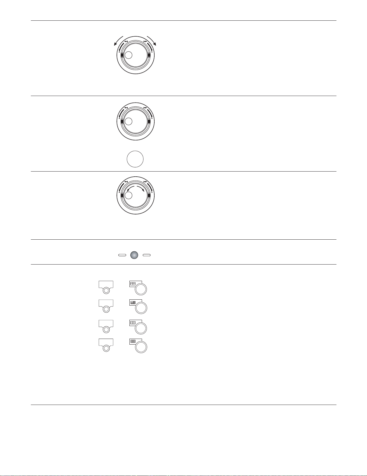
Fast forward/Fast reverse Rotating the shuttle ring will change the playback speed (1/2x, 1x, 2x,
5x, 10x, 20x) according to rotated degree. When the shuttle ring is
REV
FWD
held in the 20x position (rotated to the end) for 5 seconds, the playback speed will be 50x. When the shuttle ring is held 5 more seconds
–+
after the playback speed became 50x, the playback speed will be
100x.
Rotating the shuttle ring clockwise will play at a faster speed and
rotating it counterclockwise will play images in reverse at a faster
speed.
To play at normal speed, release the shuttle ring.
Hold playback speed Press the SET button while holding the rotated shuttle ring to hold a
REV
FWD
–+
desired playback speed. (Playback speed will be held even though
the shuttle ring is released.)
To return to the normal playback speed, press the SET button.
+
SET
Skip Rotating the jog dial during playback will skip to the next or previous
Play the latest recorded image Press the GO TO LAST button to play the latest recorded image.
Multi-screen display It is possible to display recorded images in multi-screen format
(For the WJ-HD316)
(For the WJ-HD309)
SHIFT
SHIFT
SHIFT
SHIFT
REV
FWD
recorded image.
–+
Rotating the jog dial clockwise will skip to the start time of the next
recording and start playback, and rotating it counterclockwise will
skip to the start time of the previous one. (Rotating the jog dial counterclockwise at the point around the start time of the recording will
skip to the start time of two more previous recording).
If there is no next or previous recorded image, current playback will
continue.
PA N/
TILT
GOTO
LAST
(4/7/9/10/13/16 for the WJ-HD316, 4/7/9 for the WJ-HD309).
+
1
···
+
6
q Press the SHIFT button. The SHIFT indicator will light.
w Press a camera selection button (1 - 6 for the WJ-HD316, 1 - 3 for
the WJ-HD309) to select a desired multi-screen.
Camera selection button 1: 4-split screen
Camera selection button 2: 7-split screen
Camera selection button 3: 9-split screen
+
1
···
+
3
Camera selection button 4: 16-split screen (Only for the WJHD316)
Camera selection button 5: 10-split screen (Only for the WJHD316)
Camera selection button 6: 13-split screen (Only for the WJHD316)
e To display recorded images on a single screen, press the SHIFT
button again.
After the SHIFT indicator goes off, press the camera selection button.
22
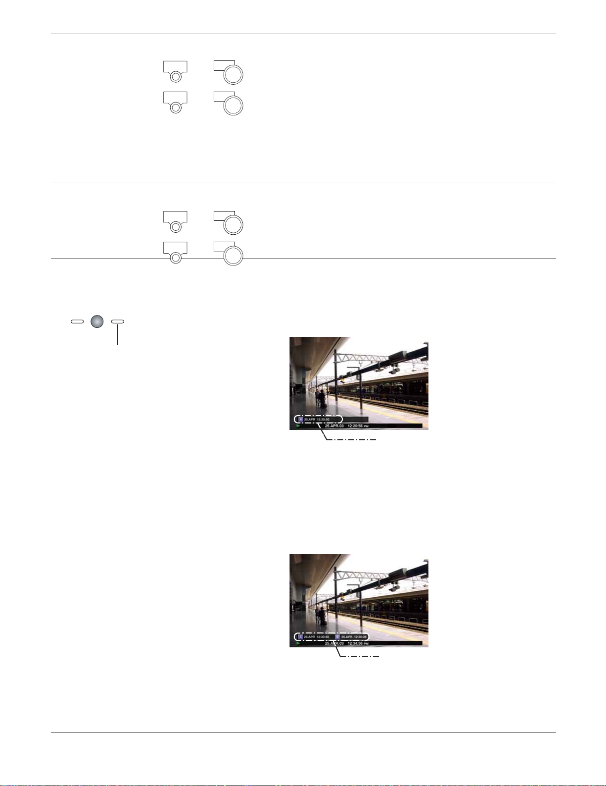
Marking It is possible to play from a marked point. Do the following to mark a
desired point.
(For the WJ-HD316)
SHIFT
Mark
+
12
1. Press the SHIFT button. The SHIFT indicator will light.
2. Press the camera selection button 12 (9 for the WJ-HD309) (MARK)
at a desired point to be marked during playback.
(For the WJ-HD309)
SHIFT
Mark
+
9
Up to 100 points can be marked. When more than 100 points are
marked, the old marked point will be overwritten by new marked
point. In this case, the oldest marked point is the first to be overwritten.
When marked while displaying in multi-screen, the same number of
split screens will be counted as marked points. (When a point is
marked while displaying a 16-split screen, 16 points will be marked
simultaneously.)
Text display It is possible to display text information attached to recorded image
while playback.
(For the WJ-HD316)
(For the WJ-HD309)
SHIFT
SHIFT
TEXT
+
11
TEXT
+
5
Text display is available only when playing on a single screen.
q Pause playback.
w Press the SHIFT button. The SHIFT indicator will light.
e Press the camera selection button 11 (5 for the WJ-HD309) (TEXT).
A - B repeat playback It is possible to play recorded images between two designated points
repeatedly.
q Designate a start point (A) by pressing the A - B REPEAT button
during playback.
ZOOM/
FOCUS
A-B
REPEAT
The A - B REPEAT indicator will light, and the time of point A will
be displayed.
Blink: During the A-B repeat playback
Light: When designating a start point (A)
Time of point A
To cancel the designated point, press the SETUP/ESC button.
w Designate an end point (B) by pressing the A - B REPEAT button
during playback.
When the start point and the end point are set, the A - B REPEAT
indicator will start blinking.
Playback between point A and B will start and keep playing
repeatedly.
The time of point A and B will be displayed during playback.
Time of point A and B
e Press the A - B REPEAT button during A - B repeat playback to
return to normal playback.
Note: Playback will be paused if the playback time caught up with
the recording time (present time) when recording and playback are performed simultaneously.
23
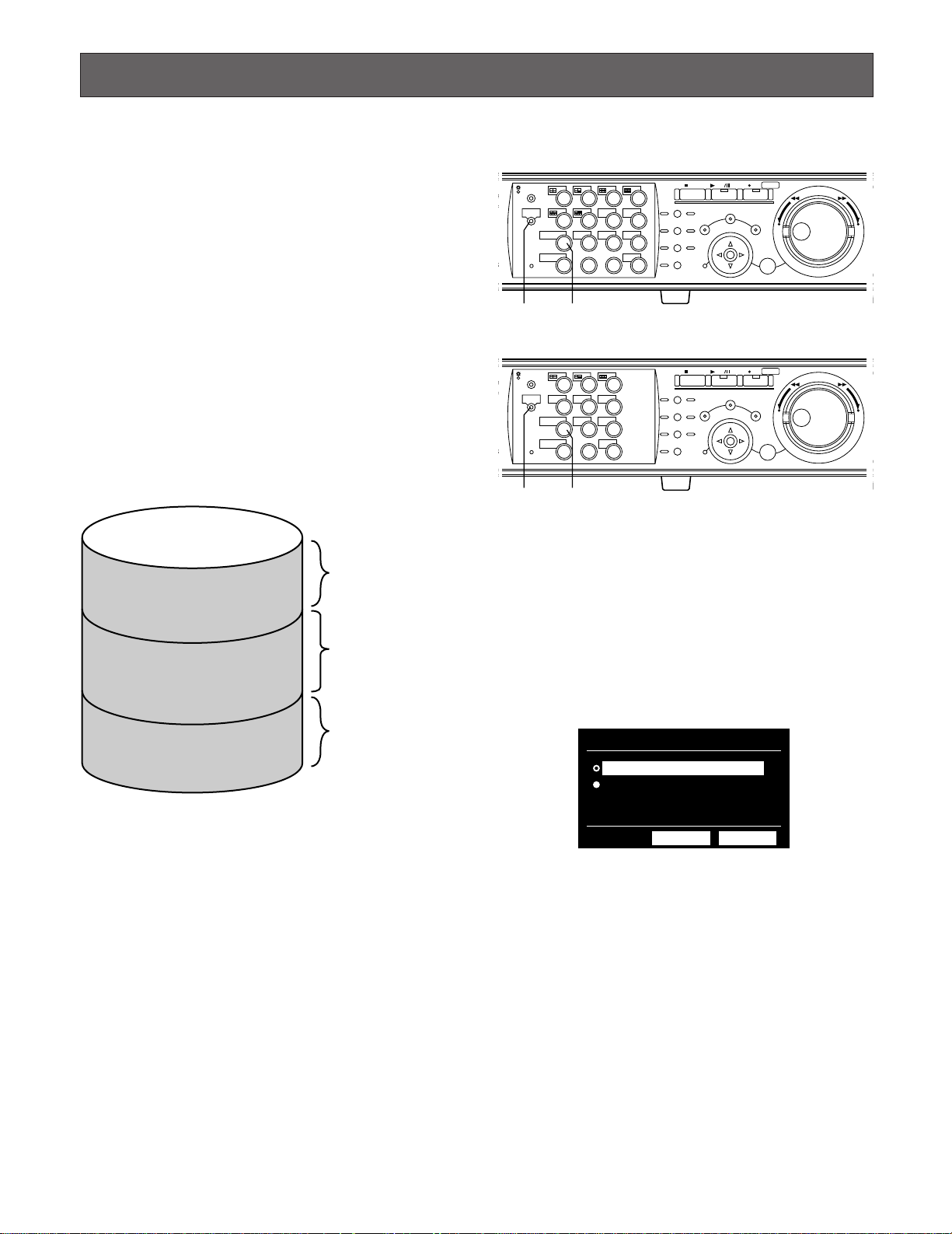
PLAYBACK IMAGE ON A DESIGNATED DISK
Images from a camera will be recorded on the built-in hard
disk or external recording devices (DVD-RAM drive, DVD-R
drive or CD-R drive) connected to this unit.
Available disk space or disks are as follows.
Note: External recording devices can be used as a copy
area for images recorded on the hard disk. It is impossible to record images on the external recording
devices directly.
HDD Normal Recording Area/Event Recording Area:
Disk space for recording on the built-in hard disk
Recorded images by manual recording (refer to page
18) or event recording will be stored in this area.
HDD Copy Area: Disk space for recording on the built-in
hard disk
Recorded images will be copied in this area (refer to
page 47).
Built-in hard disk
Recording area for
manual recording and
normal schedule
Normal recording area
Event recording area
recording
Recording area for
event recording and
emergency recording
[WJ-HD316]
STOP
PLAY PAUSE
REC
-
SEARCH
REC STOP
REV
FWD
SETUP
/ESC
–+
SET
MONITOR1
MONITOR2
DISK SELECT
EL-ZOOM
1
2
3
4
SEQSHIFT OSD
5
6
7
8
TEXT
COPY
9
13
10/0
14
MARK
11
12
LOGOUT
15
16
PAN/
TILT
ZOOM/
FOCUS
IRIS
PRESET
/AUTO
GOTO
LAST
A-B
REPEAT
LISTED
PAN/TILT
SLOW
BUSY
zx
[WJ-HD309]
STOP
PLAY PAUSE
REC
-
SEARCH
REC STOP
REV
FWD
SETUP
/ESC
–+
SET
MONITOR1
MONITOR2
DISK SELECT
EL-ZOOM
1
4
7
2
TEXTSEQSHIFT OSD
5
COPY
8
0
MARK
LOGOUT
3
6
9
PAN/
TILT
ZOOM/
FOCUS
IRIS
PRESET
/AUTO
GOTO
LAST
A-B
REPEAT
LISTED
PAN/TILT
SLOW
BUSY
z x
z Press the SHIFT button.
The SHIFT indicator will light.
x Press the camera selection button 9 (7 for the
WJ-HD309) (DISK SELECT).
The DISK SELECT window will be displayed on monitor 2
and the VGA monitor.
Recording area for
copying
Copy area
Notes:
• Playback images will be displayed only on monitor 2
and the VGA monitor.
• Playback can be performed during recording.
• Disk space size of each recording area differs depending on the settings.
Refer to a system administrator for further information.
DISK SELECT
HDD NORMAL/EVENT AREA
HDD COPY AREA
OK CANCEL
24
316
n b
STOP
PLAY PAUSE
REC
-
SEARCH
SETUP
REC STOP
REV FWD
/ESC
–
SET
MONITOR1
MONITOR2
SHIFT SEQ
DISK SELECT
EL-ZOOM
2
2
3
TEXT
11
LOGOUT
15 16
4
OSD
7
8
MARK
12
LOGOUT
PAN/
TILT
ZOOM/
FOCUS
IRIS
PRESET
/AUTO
GOTO
LAST
A-B
REPEAT
LISTED
PAN/TILT
SLOW
BUSY
1
5
6
COPY
9
10/0
1413
cvc cv
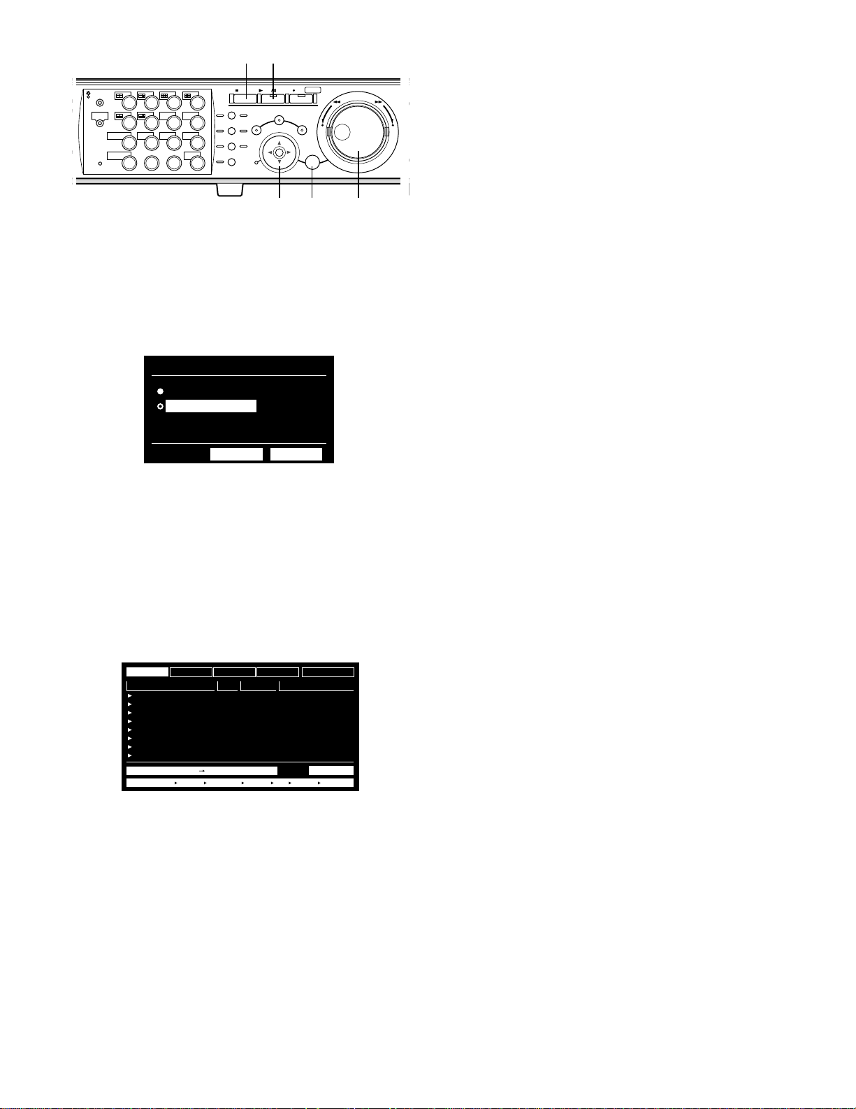
c Move the cursor to select a disk to be played
using the arrow buttons and rotate the jog dial
to check the radio button next to the selected
disk. Press the SET button to determine the
selection.
DISK SELECT
HDD NORMAL/EVENT AREA
HDD COPY AREA
OK CANCEL
n To stop playback, press the STOP button.
The indicator on the PLAY/PAUSE button will go off and
playback will stop.
Live images will be displayed on monitor 2 and the VGA
+
monitor.
Note: Pressing the PLAY/PAUSE button after stopping play-
back will start playback from the end point of the
recorded image played last time.
The recording event list window will be displayed. (Refer to
page 27 for further information.)
To close the DISK SELECT window, move the cursor to
select "CANCEL" and press the SET button.
v Rotate the jog dial to select a desired recorded
image to be played, and press the SET button
to determine the selection.
TIME&DATE
25.APR.03*12:34:56 AM
25.APR.03*12:34:56 AM
25.APR.03*12:34:56 AM
25.APR.03*12:34:56 AM
25.APR.03*12:34:56 AM
25.APR.03*12:34:56 AM
25.APR.03*12:34:56 AM
25.APR.03*12:34:56 AM
CAMERA
TIME&DATE
TIME&DATE SEARCH REC EVENT SEARCH VMD SEARCH MARK
REC EVENT
CAM REC EVT
01ch
01ch
01ch
01ch
01ch
01ch
01ch
01ch
MANUAL
MANUAL
MANUAL
MANUAL
MANUAL
MANUAL
MANUAL
MANUAL
TEXT
UNLOCK FILTER
TEXT
ABCDEFGHIJ
ABCDEFGHIJ
ABCDEFGHIJ
ABCDEFGHIJ
ABCDEFGHIJ
ABCDEFGHIJ
ABCDEFGHIJ
ABCDEFGHIJ
TOTAL25.APR.03*12:34:56 AM 25.APR.03*12:34:56 AM 100
b Press the PLAY/PAUSE button to play the
selected recorded image.
The indicator on the PLAY/PAUSE button will light and playback will start.
25

316
PLAYBACK FROM A DESIGNATED TIME AND DATE
It is possible to play recorded images from a designated
time and date without stopping recording.
Playback images will be displayed on monitor 2 and the
VGA monitor.
v c
STOP
PLAY PAUSE
REC
-
SEARCH
SETUP
/ESC
REC STOP
SET
–
REV FWD
+
MONITOR1
MONITOR2
SHIFT SEQ
DISK SELECT
EL-ZOOM
2
2
3
TEXT
11
LOGOUT
15 16
4
OSD
7
8
MARK
12
LOGOUT
PAN/
TILT
ZOOM/
FOCUS
IRIS
PRESET
/AUTO
GOTO
LAST
A-B
REPEAT
LISTED
PAN/TILT
BUSY
SLOW
1
5
6
COPY
9
10/0
1413
xxz
z Press the SEARCH button repeatedly until the
time and date designation window is displayed.
The time and date designation window will be displayed on
monitor 2 and the VGA monitor.
c Press the PLAY/PAUSE button.
The indicator on the PLAY/PAUSE button will light and start
playback from the entered time and date.
If there is no recorded image after the entered time:
When there are images recorded after the entered time, the
oldest recorded image after the entered time will be played.
When there are no images recorded after the entered time,
the newest recorded image before the entered time will be
played.
v Press the STOP button.
The indicator on the PLAY/PAUSE button will go off and
stop playback.
Live images will be displayed on monitor 2 and the VGA
monitor.
START
1
JAN
. .
TIME&DATE SEARCH REC EVENT SEARCH VMD SEARCH MARK
03
: :
12 00 00 AM
x Enter the start time using the jog dial and the
arrows button.
Select time and date using the jog dial. To move the cursor,
use the arrows button (
START
2
. .
TIME&DATE SEARCH REC EVENT SEARCH VMD SEARCH MARK
FEB
AB).
04
: :
12 00 00 AM
26

SEARCH AND PLAY
TIME&DATE
01ch
01ch
01ch
01ch
01ch
01ch
01ch
01ch
MANUAL
MANUAL
MANUAL
MANUAL
MANUAL
MANUAL
MANUAL
MANUAL
CAM REC EVT
ABCDEFGHIJ
ABCDEFGHIJ
ABCDEFGHIJ
ABCDEFGHIJ
ABCDEFGHIJ
ABCDEFGHIJ
ABCDEFGHIJ
ABCDEFGHIJ
TEXT
25.APR.03*12:34:56 AM
25.APR.03*12:34:56 AM
25.APR.03*12:34:56 AM
25.APR.03*12:34:56 AM
25.APR.03*12:34:56 AM
25.APR.03*12:34:56 AM
25.APR.03*12:34:56 AM
25.APR.03*12:34:56 AM
TIME&DATE SEARCH REC EVENT SEARCH VMD SEARCH MARK
TIME&DATE
CAMERA
REC EVENT
TEXT
UNLOCK FILTER
TOTAL25.APR.03*12:34:56 AM 25.APR.03*12:34:56 AM 100
There are 3 ways to search for a recorded image and play it.
• Search for a recording event and play it (Recording event search)
• Search for a motion detected time and date from recorded images and play it (VMD search)
• Search for a marked point and play it (Marking search)
Note: Playback images will be displayed on a single screen on monitor 2 and the VGA monitor. To play in a multi-screen,
switch to a multi-screen after starting playback.
■ Searching For a Recording Event and Playback (Recording Event
Search)
Display a list or a thumbnail of recording events, and select the desired recording event from them to play it.
It is possible to search using the following filters:
Searching Filters
TIME & DATE Search for only images recorded in the entered time range.
CAMERA Search for only recorded images from the selected camera channel.
REC EVENT Search for only images recorded in the selected recording mode.
It is possible to search for images recorded in the following recording modes:
EMERGENCY: Emergency recording (Refer to page 20.)
VMD: Event recording performed when motion had been detected (Refer to page 31.)
TERMINAL: Event recording performed when a terminal alarm had been detected.
COMMAND: Event recording performed when a command alarm had been detected.
VIDEO LOSS: Event recording performed when video loss had occurred.
MANUAL: Manual recording (Refer to page 18.)
SCHEDULE: Schedule recording (Refer to page 103.)
TEXT Search for only images recorded with text information
● Recording Event List Window
Camera Channel
Time and date
Time range of listed data
Searching filter buttons
Filter cancel button
Recording event
Text information
Number of listed data
Searching information
27
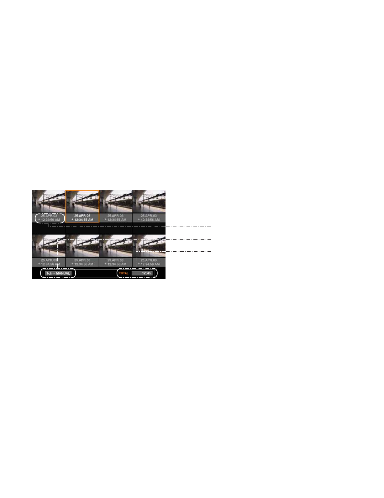
Searching filter buttons: Selects the searching filter
Filter cancel button: Cancels the selected searching filter and lists all recording events
Time and date: <When searched by recording event>
Time when recording started will be displayed.
<When searched by VMD>
Time when motion had been detected will be displayed.
<When searched by marked point>
Time when the point was marked will be displayed.
Camera channel: Camera channel of the recorded image will be displayed. The recorded image of the
displayed camera channel will be played on a single screen.
Recording event: Recording mode will be displayed.
Text information: First several characters of text information will be displayed if the image has text infor-
mation.
Time range of the listed data: Time range of the listed data will be displayed.
Number of the listed data: Number of the listed data will be displayed.
Searching information: Searching filter will be displayed. (A filter of the currently displayed list will be displayed
in orange.)
● Recording Event Thumbnail Window
Time and date
Camera channel/Recording event
Number of listed data
Time and date: <When searched by recording event>
Time when recording started will be displayed.
<When searched by VMD>
Time when motion had been detected will be displayed.
<When searched by marked point>
Time when the point was marked will be displayed.
Camera channel/Recording event: Camera channel of the recorded image will be displayed. The recorded image of the
displayed camera channel will be played on a single screen. Recording mode also will
be displayed.
Number of the listed data: Number of the listed data will be displayed.
Note: Some images displayed in the thumbnail window may not match with respective displayed recorded time.
28
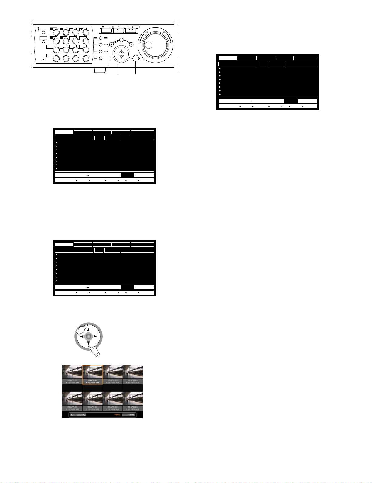
316
STOP
PLAY PAUSE
REC
-
SEARCH
SETUP
/ESC
REC STOP
SET
x
–
REV FWD
+
MONITOR1
MONITOR2
SHIFT SEQ
DISK SELECT
EL-ZOOM
2
2
3
TEXT
11
LOGOUT
15 16
4
OSD
7
8
MARK
12
LOGOUT
PAN/
TILT
ZOOM/
FOCUS
IRIS
PRESET
/AUTO
GOTO
LAST
A-B
REPEAT
LISTED
PAN/TILT
SLOW
BUSY
1
5
6
COPY
9
10/0
1413
zz
x
z Press the SEARCH button repeatedly until the
recording event list window is displayed.
TIME&DATE
25.APR.03*12:34:56 AM
25.APR.03*12:34:56 AM
25.APR.03*12:34:56 AM
25.APR.03*12:34:56 AM
25.APR.03*12:34:56 AM
25.APR.03*12:34:56 AM
25.APR.03*12:34:56 AM
25.APR.03*12:34:56 AM
The recording event list window will be displayed on monitor 2 and the VGA monitor.
Use the arrows button (
window and the thumbnail window alternately.
To search using a searching filter, go to step 4.
CAMERA
TIME&DATE
TIME&DATE SEARCH REC EVENT SEARCH VMD SEARCH MARK
REC EVENT
CAM REC EVT
01ch
01ch
01ch
01ch
01ch
01ch
01ch
01ch
MANUAL
MANUAL
MANUAL
MANUAL
MANUAL
MANUAL
MANUAL
MANUAL
TEXT
UNLOCK FILTER
TEXT
ABCDEFGHIJ
ABCDEFGHIJ
ABCDEFGHIJ
ABCDEFGHIJ
ABCDEFGHIJ
ABCDEFGHIJ
ABCDEFGHIJ
ABCDEFGHIJ
TOTAL25.APR.03*12:34:56 AM 25.APR.03*12:34:56 AM 100
CD) to switch displaying the list
x Use the arrows button (AB) to select a
searching filter (TIME & DATE, CAMERA,
EVENT, TEXT), and press the SET button.
TIME&DATE
25.APR.03*12:34:56 AM
25.APR.03*12:34:56 AM
25.APR.03*12:34:56 AM
25.APR.03*12:34:56 AM
25.APR.03*12:34:56 AM
25.APR.03*12:34:56 AM
25.APR.03*12:34:56 AM
25.APR.03*12:34:56 AM
When a searching filter is selected, the respective searching filter window will be displayed.
Select "UNLOCK FILTER" and press the SET button to cancel the selected filter.
Refer to page 27 about the searching filters.
CAMERA
TIME&DATE
TIME&DATE SEARCH REC EVENT SEARCH VMD SEARCH MARK
REC EVENT
CAM REC EVT
01ch
01ch
01ch
01ch
01ch
01ch
01ch
01ch
MANUAL
MANUAL
MANUAL
MANUAL
MANUAL
MANUAL
MANUAL
MANUAL
TEXT
UNLOCK FILTER
TEXT
ABCDEFGHIJ
ABCDEFGHIJ
ABCDEFGHIJ
ABCDEFGHIJ
ABCDEFGHIJ
ABCDEFGHIJ
ABCDEFGHIJ
ABCDEFGHIJ
TOTAL25.APR.03*12:34:56 AM 25.APR.03*12:34:56 AM 100
TIME&DATE
25.APR.03*12:34:56 AM
25.APR.03*12:34:56 AM
25.APR.03*12:34:56 AM
25.APR.03*12:34:56 AM
25.APR.03*12:34:56 AM
25.APR.03*12:34:56 AM
25.APR.03*12:34:56 AM
25.APR.03*12:34:56 AM
CAMERA
TIME&DATE
TIME&DATE SEARCH REC EVENT SEARCH VMD SEARCH MARK
REC EVENT
CAM REC EVT
01ch
01ch
01ch
01ch
01ch
01ch
01ch
01ch
MANUAL
MANUAL
MANUAL
MANUAL
MANUAL
MANUAL
MANUAL
MANUAL
TEXT
UNLOCK FILTER
TEXT
ABCDEFGHIJ
ABCDEFGHIJ
ABCDEFGHIJ
ABCDEFGHIJ
ABCDEFGHIJ
ABCDEFGHIJ
ABCDEFGHIJ
ABCDEFGHIJ
TOTAL25.APR.03*12:34:56 AM 25.APR.03*12:34:56 AM 100
<List window>
⇔
<Thumbnail window>
29

MONITOR1
316
MONITOR2
SHIFT SEQ
DISK SELECT
EL-ZOOM
2
b
STOP
PLAY PAUSE
REC
-
REC STOP
2
3
TEXT
11
LOGOUT
15 16
4
OSD
7
8
MARK
12
LOGOUT
PAN/
TILT
ZOOM/
FOCUS
IRIS
PRESET
/AUTO
GOTO
LAST
A-B
REPEAT
LISTED
PAN/TILT
BUSY
SLOW
SEARCH
SETUP
/ESC
1
5
6
COPY
9
10/0
1413
REV FWD
–
SET
cc
c
+
v
Filter recording events by recording event
REC EVENT FILTERING
EMERGENCY
VMD
TERMINAL
COMMAND
VIDEO LOSS
MANUAL
SCHEDULE
SET : [ SET ] CANCEL : [ ESC ]
OFF
ON
ON
ON
ON
ON
ON
c Filter recording events.
Filter recording events by time and date
TIME&DATE FILTERING
■
START
..
1 JAN 03
END
..
1JAN03 0 00
SET : [SET] CANCEL : [ESC]
Move the cursor using the arrows button and rotate the jog
dial to enter time and date.
Press the SET button to determine the entered time and
date.
The recording event in the entered time range will be listed
and displayed.
Filter recording events by camera channel
CAMERA FILTERING
CAMERA
1
2345
9 10 11 12 13 14 15 16
SET : [ SET ] CANCEL : [ ESC ]
Select camera channel numbers (1 - 16 for the WJ-HD316,
1 - 9 for the WJ-HD309) using the arrows button to apply filtering.
The selected camera channels will turn to white.
Press the SET button to determine the selection of camera
channel numbers.
The recording events of the selected camera channels will
be listed.
Note: When operating the system controller, select a cam-
era channel using the numeric keypad. In this case, it is
impossible to select 10 CH to 16 CH.
: AM
00 00
: AM
6 78
Move the cursor to select the recording event (refer to page
27) using the arrows button (
CD) and rotate the jog dial to
ON.
Press the SET button to determine the selection.
The recording events of the selected filter will be listed.
Filter recording events by text information
TEXT FILTERING
WITHOUT TEXT
SET : [ SET ] CANCEL : [ ESC ]
Rotate the jog dial to select OFF, WITH TEXT or WITHOUT
TEXT.
Press the SET button to determine the selection.
The recording events filtered by the selected filter will be
listed.
v Rotate the jog dial to select a recording event
to be played.
TIME&DATE
25.APR.03*12:34:56 AM
25.APR.03*12:34:56 AM
25.APR.03*12:34:56 AM
25.APR.03*12:34:56 AM
25.APR.03*12:34:56 AM
25.APR.03*12:34:56 AM
25.APR.03*12:34:56 AM
25.APR.03*12:34:56 AM
CAMERA
TIME&DATE
TIME&DATE SEARCH REC EVENT SEARCH VMD SEARCH MARK
REC EVENT
CAM REC EVT
01ch
01ch
01ch
01ch
01ch
01ch
01ch
01ch
MANUAL
MANUAL
MANUAL
MANUAL
MANUAL
MANUAL
MANUAL
MANUAL
TEXT
UNLOCK FILTER
TEXT
ABCDEFGHIJ
ABCDEFGHIJ
ABCDEFGHIJ
ABCDEFGHIJ
ABCDEFGHIJ
ABCDEFGHIJ
ABCDEFGHIJ
ABCDEFGHIJ
TOTAL25.APR.03*12:34:56 AM 25.APR.03*12:34:56 AM 12345
b Press the PLAY/PAUSE button.
The LISTED indicator and the indicator on the PLAY/PAUSE
button will light and playback of the selected recording
event will start.
Note: When the LISTED indicator is lit, only listed recording
events are available to be played. Press the LISTED
button during playback to make all recording events
available to be played.
30
Loading...