


 Loading...
Extension Unit
Instructions
Model No. WJ-HDE300
Extension |
|
|
Unit |
WJ- |
300 |
HDE |
|
Before attempting to connect or operate this product,
please read these instructions carefully and save this manual for future use.

WARNING:
•To prevent fire or electric shock hazard, do not expose this appliance to rain or moisture. The apparatus shall not be exposed to dripping or splashing and that no objects filled with liquids, such as vases, shall be placed on the apparatus.
•All work related to the installation of this product should be made by qualified service personnel or system installers.
CAUTION:
•Read the label on the rear of the unit for identification of this product, and the power ratings.
CAUTION
RISK OF ELECTRIC SHOCK
DO NOT OPEN
CAUTION: TO REDUCE THE RISK OF ELECTRIC SHOCK,
DO NOT REMOVE COVER (OR BACK).
NO USER-SERVICEABLE PARTS INSIDE.
REFER SERVICING TO QUALIFIED SERVICE PERSONNEL.
|
The lightning flash with arrowhead sym- |
|
|
bol, within an equilateral triangle, is |
|
|
intended to alert the user to the pres- |
|
|
ence of uninsulated "dangerous voltage" |
|
|
within the product's enclosure that may |
|
SA 1965 |
be of sufficient magnitude to constitute a |
|
risk of electric shock to persons. |
||
|
The exclamation point within an equilateral triangle is intended to alert the user to the presence of important operating and maintenance (servicing) instructions in the literature accompanying the appliance.
SA 1966
Power disconnection. Unit with or without ON-OFF switches have power supplied to the unit whenever the power cord is inserted into the power source; however, the unit is operational only when the ON-OFF switch is in the ON position. The power cord is the main power disconnect for all units.
For Canada
This Class A digital apparatus complies with canadian ICES-003.
Cet appareil numérique de la classe A est conforme à la norme NMB-003 du Canada.
For U.S.A.
NOTE: This equipment has been tested and found to comply with the limits for a Class A digital device, pursuant to Part 15 of the FCC Rules. These limits are designed to provide reasonable protection against harmful interference when the equipment is operated in a commercial environment. This equipment generates, uses, and can radiate radio frequency energy and, if not installed and used in accordance with the instruction manual, may cause harmful interference to radio communications.
Operation of this equipment in a residential area is likely to cause harmful interference in which case the user will be required to correct the interference at his own expense.
FCC Caution: To assure continued compliance, (example - use only shielded interface cables when connecting to computer or peripheral devices). Any changes or modifications not expressly approved by the party responsible for compliance could void the user’s authority to operate this equipment.
The serial number of this product may be found on the rear of the unit.
You should note the serial number of this unit in the space provided and retain this book as a permanent record of your purchase to aid identification in the event of theft.
Model No. |
WJ-HDE300 |
Serial No.
2

■ Important Safety Instructions
1)Read these instructions.
2)Keep these instructions.
3)Heed all warnings.
4)Follow all instructions.
5)Do not use this apparatus near water.
6)Clean only with dry cloth.
7)Do not block any ventilation openings. Install in accordance with the manufacturer's instructions.
8)Do not use near any heat sources such as radiators, heat registers, stoves, or other apparatus (including amplifiers) that produce heat.
9)Do not defeat the safety purpose of the polarized or grounding-type plug. A polarized plug has two blades with one wider than the other. A grounding-type plug has two blades and a third grounding prong. The wide blade or the third prong are provided for your safety. If the provided plug does not fit into your outlet, consult an electrician for replacement of the obsolete outlet.
10)Protect the power cord from being walked on or pinched particularly at plugs, convenience receptacles and the points where they exit from the apparatus.
11)Only use attachments/accessories specified by the manufacturer.
12)Use only with the cart, stand, tripod, bracket, or table specified by the manufacturer, or sold with the apparatus. When a cart is used, use caution when moving the cart/apparatus combination to avoid injury from tip-overs.
S3125A
13)Unplug this apparatus during lightning storms or when unused for long periods of time.
14)Refer all servicing to qualified service personnel. Servicing is required when the apparatus has been damaged in any way, such as power-supply cord or plug is damaged, liquid has been spilled or objects fallen into the apparatus, the apparatus has been exposed to rain or moisture, does not operate normally, or has been dropped.
3
Contents |
|
■ Important Safety Instructions . . . . . . . . . . . . . . . . . . . . . . . . . . . . . . . |
3 |
■ General . . . . . . . . . . . . . . . . . . . . . . . . . . . . . . . . . . . . . . . . . . . . . . . |
5 |
■ Precautions . . . . . . . . . . . . . . . . . . . . . . . . . . . . . . . . . . . . . . . . . . . . |
5 |
■ Appearance . . . . . . . . . . . . . . . . . . . . . . . . . . . . . . . . . . . . . . . . . . . . |
6 |
● Front View . . . . . . . . . . . . . . . . . . . . . . . . . . . . . . . . . . . . . . . . . . . |
6 |
● Rear View . . . . . . . . . . . . . . . . . . . . . . . . . . . . . . . . . . . . . . . . . . . . |
7 |
● Inside the Front Lid . . . . . . . . . . . . . . . . . . . . . . . . . . . . . . . . . . . . |
8 |
■ Replacing/Mounting HDDs . . . . . . . . . . . . . . . . . . . . . . . . . . . . . . . . |
9 |
● Procedures . . . . . . . . . . . . . . . . . . . . . . . . . . . . . . . . . . . . . . . . . . |
9 |
■ Mounting in a Rack . . . . . . . . . . . . . . . . . . . . . . . . . . . . . . . . . . . . . . . |
12 |
● Unit Layout . . . . . . . . . . . . . . . . . . . . . . . . . . . . . . . . . . . . . . . . . . . |
12 |
● How to Mount . . . . . . . . . . . . . . . . . . . . . . . . . . . . . . . . . . . . . . . . . |
13 |
■ Connections . . . . . . . . . . . . . . . . . . . . . . . . . . . . . . . . . . . . . . . . . . . . |
14 |
● Procedures . . . . . . . . . . . . . . . . . . . . . . . . . . . . . . . . . . . . . . . . . . |
14 |
■ Setup Procedures . . . . . . . . . . . . . . . . . . . . . . . . . . . . . . . . . . . . . . . |
15 |
● Basic Setups . . . . . . . . . . . . . . . . . . . . . . . . . . . . . . . . . . . . . . . . . |
15 |
● Changing Setups . . . . . . . . . . . . . . . . . . . . . . . . . . . . . . . . . . . . . |
18 |
● Recovery of RAID5 Disk . . . . . . . . . . . . . . . . . . . . . . . . . . . . . . . . |
21 |
● Unit Number Check . . . . . . . . . . . . . . . . . . . . . . . . . . . . . . . . . . . . |
23 |
■ Troubleshooting . . . . . . . . . . . . . . . . . . . . . . . . . . . . . . . . . . . . . . . . . |
26 |
■ Specifications . . . . . . . . . . . . . . . . . . . . . . . . . . . . . . . . . . . . . . . . . . . |
27 |
■ Accessories . . . . . . . . . . . . . . . . . . . . . . . . . . . . . . . . . . . . . . . . . . . . |
27 |
4
■ General
The extension unit WJ-HDE300 can accommodate up to four hard disk drives per unit to add available disk space to the digital disk recorder WJ-HD316A/WJ-HD309A series. Up to seven extension units can be connected to a digital disk recorder. The units can be operated in RAID level 5* mode for high tolerance to disk error.
*RAID level 5 (Redundant Arrays for Independent Disks, independent data disks with distributed parity blocks)
RAID level 5 regards 3 or more drives as one drive, and it is possible to read data by automatically attaching error correction data even though one of the drives is broken. (It is impossible to read data if 2 or more drives are broken.)
RAID level 5 requires a minimum of 3 drives per unit.
When using the RAID function, the logical disk size of the extension unit will be as below.
Logical disk size = Smallest size of the disk among the disks in the extension unit x (Number of the disks in the extension unit - 1) The actual space may be several percent lower than the logical space.
*Important
When set to RAID level 5, the digital disk recorder will not access the HDD preinstalled in it, but will access only the HDDs in the extension unit.
■ Precautions
•Do not operate the appliance beyond its specified temperature, humidity or power source ratings.
Do not use the appliance in an extreme environment where a high temperature or high humidity exists. Use the appliance at temperatures within +5 °C to +45 °C (41 °F to 113 °F) and humidity below 85 %.
The input power source for this appliance is 120 V AC 60 Hz.
•Avoid shock and vibration
Shock or vibration may damage the HDD.
The HDDs are fragile especially when the HDD motors are revolving and the HDD POWER indicator lights. Be sure to turn off either switch: the POWER switch on the rear panel, or the HDD POWER switch inside the front lid: before you mount the unit into a rack or dismount it. Do not move the HDD for 30 seconds after turning off the power.
•Pay attention to static electricity
Put your hand on a metallic surface to discharge static electricity before installation.
Do not touch components mounted on the HDD directly with your hand.
Hold only the two sides of the HDD when installing.
•Avoid condensation on the surface of the HDD.
If this happens, do not turn on the power of the appliance and leave the appliance for around 2 hours.
Wait until the dew evaporates in any of the following cases.
•The appliance is moved to a place significantly different in temperature or humidity.
•The appliance is moved out from an air-conditioned room.
•The appliance is placed in an extremely humid place.
•The appliance is placed in a room where a heater has just been turned on.
•Consumable parts
Contact your dealer about replacement when the time comes.
A hard disk drive needs replacing after a certain length (depends on the model) of operation.
Cooling fans also need replacing after around 20 000 - 30 000 hours of operation.
•Do not block the ventilation opening or slots on the cover.
To prevent the appliance from overheating, place it at least 5 cm (2 inches) away from the wall.
•Avoid placing the unit on an inclined surface. Otherwise, malfunction or damage to the disk may occur. Place the unit in a horizontal position.
5

■ Appearance
● Front View
q w e |
r |
t |
|
|
|
|
|
|
|
|
|
ERROR |
|
|
|
|
HDD |
HDD 1 |
HDD 2 |
HDD 3 |
HDD 4 |
POWER |
|
|
|
|
OPERATE |
|
|
|
|
Extension Unit
WJ-HDE
qError indicator [ERROR]
Lights when an error occurs. Refer to Troubleshooting for details.
Red: System error
Orange: Thermal error or malfunction of the cooling fan.
wHDD power indicator [HDD POWER] ON: Indicates that the HDDs are powered.
OFF: Indicates that the HDDs are not powered.
Notes:
•Do not move or shock the unit while this indicator is lit. Otherwise, the HDDs will be damaged.
•This indicator will light and go out by the setting of the HDD POWER switch inside the front lid of the unit, or by the operation on the HDD SAFETY MENU of the digital disk recorder.
eOperate indicator [OPERATE]
Lights green when turning on the power switch on the rear panel.
rHDD access indicators [HDD 1] [HDD 2] [HDD 3] [HDD 4]
Each indicator lights to indicate the status of the respective HDD.
Green: Indicates that the respective HDD is running normally.
Red: Indicates that the respective HDD is the first faulty drive among the HDDs in the unit.
Red blink: Indicates that the respective HDD is the second or subsequent faulty drive among the HDDs in the unit.
Orange-red alternate blink/Orange: Indicates that the respective drive is currently being recovered in RAID level 5 mode.
These indicators normally show the status of the respective drive, but they work as a set when a system error occurs. Refer to Troubleshooting for further information.
Important
When one of the indicators lights red, replace the respective HDD immediately. If two or more indicators light/blink red, it will be impossible to recover data. There may be cases where it is eventually impossible to recover data if two drives are coincidentally damaged or the second drive fails during the data recovery process.
tFront cover
Detach the front cover when it is necessary to install HDDs or to operate the switches inside the unit.
6
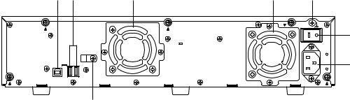
● Rear View
y u |
i |
i |
o |
|
|
|
|
SIGNAL GND |
|
|
|
|
|
!0 |
|
|
|
POWER |
|
EXT |
|
|
|
|
IN OUT |
|
|
|
!1 |
2 1 |
|
|
AC IN |
!2
ySerial in connector [IN]
Connect the WJ-HD300 series digital disk recorder or other extension unit with the supplied serial cable.
uSerial out connector [OUT1] [OUT2]
Connect another extension unit with the supplied serial cable.
i Cooling fan
oSignal GND terminal [SIGNAL GND]
Connect this terminal if required, to the SIGNAL GND terminal of other equipment to avoid a possible grounding loop and noise.
!0Power switch [POWER]
Turn on the power of the unit with this switch before turning on the power of the digital disk recorder, or turn them on simultaneously. Otherwise, the HDDs will not be mounted.
When turning off the power of the unit with this switch, turn off the power of the digital disk recorder first, and then turn off the power of this unit after confirming that all HDD access indicators are not lit or blinking.
!1AC inlet [AC IN]
Connect the supplied power cord.
!2Cable clamp
7

● Inside the Front Lid
q’ |
!3 |
RESET |
|
|
|
||
w’ |
|
MODE |
|
!4 |
SINGLE RAID5 |
||
|
|||
e’ |
|
HDD POWER |
|
!5 OFF ON |
|||
|
|||
|
!6 |
RECOVER |
|
|
|
||
q' Error indicators
Functions the same as on the front panel. Red: System error
Orange: Thermal error or malfunction of the cooling fan.
w' HDD power indicator
Functions the same as on the front panel. ON: Indicates that HDDs are powered.
OFF: Indicates that the HDDs are not powered.
e' Operate indicator
Functions the same as on the front panel.
Lights green when turning on the power switch on the rear panel.
!3Reset button [RESET]
This button is located inside the unit. To access this button, it is necessary to detach the front cover. Press this button using a small screw driver (not supplied).
•When SINGLE is selected
After adding or replacing any of the HDDs, press this button only. Refer to Setup Procedures for details.
•When RAID 5 is selected
This button is used in combination with the RECOVER button and MODE switch after adding or replacing any of the HDDs. Refer to Setup Procedures for details.
Important
Do not press the RESET button and the RECOVER button simultaneously when SINGLE is selected. Otherwise, the setting of the digital disk recorder may be initialized and it may cause a malfunction.
!4Mode switch [MODE]
RAID 5: Applies RAID level 5 mode (striping at the byte level also stripe error correction information).
SINGLE: Applies SINGLE mode (no striping across drives for data or error correction information). Default position
Important
•Changing the MODE switch will not be accepted when the ERROR indicator lights red and/or when HDD 1-4 indicate a system error status by lighting red and orange. When this happens, ask your dealer to solve the error.
•When set to RAID5, the HDD preinstalled in the digital disk recorder will not work. Instead, it is applied only to the HDDs installed in the extension unit and the digital disk recorder will perform storage and readout of the image data by accessing the extension unit.
•The MODE switches of all extension units in a system should be set to the same position, SINGLE or RAID5. Otherwise, the system will malfunction.
•The available disk space of the unit can be logically calculated as follows. The actual space may be several percent lower than you calculated depending on the HDD type used and their combination. The most efficient way is to use the same type drives.
When SINGLE is selected, it will be the sum of all the HDD sizes.
When RAID 5 is selected, it will be as follows.
When 3 HDDs are in the unit: It will be double the size of the smallest HDD size.
When 4 HDDs are in the unit: It will be triple the size of the smallest HDD size.
For example, if 4 HDDs of 80 GB, 120 GB, and two 160 GB are mounted, the available disk space will be 80 G x 3 = 240 GB.
!5HDD power switch [HDD POWER]
Use this switch in the ON position for normal operation. ON: Supplies the power to the HDDs and the HDD
power indicators will light. Default position
OFF: Does not supply the power and the HDD power indicators will go out.
!6Recover button [RECOVER]
Use this button with the RESET button after replacing the HDDs used in the RAID 5 mode to start data recovery.
Refer to page 12 for details.
8

■ Replacing/Mounting HDDs
Up to four HDDs (locally procured) can be installed in an extension unit.
HDD 2 |
HDD 4 |
HDD 1 |
HDD 3 |
Important
•Type of hard disk drive
Consult your dealer about hard disk drives. Use only hard disk drives compatible with the extension unit. If unauthorized hard disk drives are used, it may cause a system error.
It is recommended that the same type drives having the same capacity should be installed in the extension units to maximize the usable capacity.
•The HDDs should be installed in the proper positions in the order as shown above. Do not skip or reverse the order of the HDD positions. Otherwise, the recorder will not recognize the extension unit or wrongly mounted drives.
•The MODE switches of all units in a system should be set to the same position, SINGLE or RAID5. When mixed, it will cause a system error. See Troubleshooting for details.
•When applying the RAID5 mode, it requires a minimum of 3 drives per unit. When only two drives are mounted in position #1 and #2, the ERROR indicator will be lit red, HDD3 indicator will be lit red, and HDD4 indicator will blink red.
•When applying the RAID5 mode, the digital disk recorder will not access the HDD preinstalled in it, but will access only the HDDs in the extension unit.
•Do not change the installed positions after the system has been operated. Otherwise, data readout will not be performed
• The replaced/added HDDs will be formatted.
SINGLE mode: Only the replaced/added HDD will be formatted. For example, when the HDD 4 of the extension unit 2 is replaced, only the HDD4 of the extension unit 2 will be formatted.
RAID 5 mode: All the HDDs of the extension units will be formatted when a new HDD is added or a preinstalled HDD is removed. For example, when the HDD 4 of the extension unit 2 is added, all the HDDs of the extension unit 2 will be formatted.
●Procedures
1.HDD power-off procedures
Perform either of the following procedures depending on the installation situations to stop the HDD motors.
Case 1: When the rear of the units is accessible, turn off the power switches of the digital disk recorder first, and turn off extension units.
POWER
Case 2: When the rear of the units is inaccessible, for example when mounted in a rack, open the SETUP MENU of the digital disk recorder and set the HDD SAFETY MODE to ON. The extension units will turn to the HDD power-off mode.
Refer to Setup Procedures of this manual and the Operating Instructions included with the digital disk recorder for details .
2. Detach the front cover and the front panel.
2 - 1
2-1 Remove the two screws.
9
Loading...