


WJ-SX550
Table of contents
 Loading...
Before attempting to connect or operate this product,
please read these instructions carefully and save this manual for future use.
System 500 Matrix Switcher
Operating Instructions
ALARM
ACK
RESET
AUX
DEC
-1CAM
INC
+1CAM
STOP
SLOW
ESC
SET
MON
CAM
WIDE
FAR
AF
ZOOM
TELE
FOCUS
NEAR
RESET
IRIS
1
2
3
4
5
6
7
8
0
9
CLOSE OPEN
1 2
BACK
SEQ
F
O
R
W
A
R
D
SEQ
ALT
BUSY
F1
F2
F3
F4
System
Controller W
V-CU CJ
550
Matrix Switcher
Model No.
WJ-SX550C
System Controller
Model No.
WV-CU550CJ
ENGLISH
DEUTSCH
FRANÇAIS

2
ENGLISH VERSION
The serial number of this product may be found on the rear
of the unit.
You should note the serial number of this unit in the space
provided and retain this book as a permanent record of your
purchase to aid identification in the event of theft.
Model No.
Serial No.
The lightning flash with arrowhead symbol,
within an equilateral triangle, is interned to
alert the user to the presence of uninsulated
"dangerous voltage" within the product's
enclosure that may be of sufficient magni-
tude to constitute a risk of electric shock to
persons.
The exclamation point within an equilateral
triangle is intended to alert the user to the
presence of important operating and mainte-
nance (servicing) instructions in the litera-
ture accompanying the appliance.
Wij verklaren als enige aansprakelijke, dat het product waarop deze
verklaring betrekking heeft, voldoet aan de volgende normen of andere
normatieve documenten, overeenkomstig de bepalingen van Richtlijnen
73/23/EEC en 89/336/EEC.
Vi erklærer os eneansvarlige for, at dette produkt, som denne deklara-
tion omhandler, er i overensstemmelse med standarder eller andre nor-
mative dokumenter i følge bestemmelserne i direktivene 73/23/EEC og
89/336/EEC.
Vi deklarerar härmed värt fulla ansvar för att den produkt till vilken
denna deklaration hänvisar är i överensstämmelse med standarddoku-
ment, eller andra normativa dokument som framställs i EEC-direktiv nr.
73/23 och 89/336.
Ilmoitamme yksinomaisella vastuullamme, että tuote, jota tämä ilmoitus
koskee, noudattaa seuraavia standardeja tai muita ohjeellisia asiakirjoja,
jotka noudattavat direktiivien 73/23/EEC ja 89/336/EE. säädöksiä.
Vi erklærer oss alene ansvarlige for at produktet som denne erklæringen
gjelder for, er i overensstemmelse med følgende normer eller andre nor-
mgivende dokumenter som følger bestemmelsene i direktivene
73/23/EEC og 89/336/EEC.
We declare under our sole responsibility that the product to which this
declaration relates is in conformity with the standards or other normative
documents following the provisions of Directives EEC/73/23 and
EEC/89/336.
Noi dichiariamo sotto nostra esclusiva responsabilità che il prodotto a
cui si riferisce la presente dichiarazione risulta conforme ai seguenti
standard o altri documenti normativi conformi alle disposizioni delle
direttive CEE/73/23 e CEE/89/336.
FOR YOUR SAFETY PLEASE READ THE FOLLOWING TEXT CARE-
FULLY.
This appliance is supplied with a moulded three pin mains plug for your
safety and convenience.
A 13 amp fuse is fitted in this plug.
Should the fuse need to be replaced please ensure that the replacement
fuse has a rating of 13 amp and that it is approved by ASTA or BSI to
BS1362.
Check for the ASTA mark
H or the BSI mark G on the body of the
fuse.
If the plug contains a removable fuse cover you must ensure that it is
refitted when the fuse is replaced.
If you lose the fuse cover the plug must not be used until a replacement
cover is obtained.
A replacement fuse cover can be purchased from your local Panasonic
Dealer.
IF THE FITTED MOULDED PLUG IS UNSUITABLE FOR THE SOCK-
ET OUTLET IN YOUR HOME THEN THE FUSE SHOULD BE
REMOVED AND THE PLUG CUT OFF AND DISPOSED OF SAFELY.
THERE IS A DANGER OF SEVERE ELECTRICAL SHOCK IF THE
CUT OFF PLUG IS INSERTED INTO ANY 13 AMP SOCKET.
If a new plug is to be fitted please observe the wiring code as shown
below.
If in any doubt please consult a qualified electrician.
WARNING: This apparatus must be earthed.
IMPORTANT
The wires in this mains lead are coloured in accordance with the follow-
ing code.
Green-and-yellow: Earth
Blue: Neutral
Brown: Live
As the colours of the wire in the mains lead of this appliance may not
correspond with the coloured markings identifying the terminals in your
plug, proceed as follows.
The wire which is coloured green-and-yellow must be connected to
the terminal in the plug which is marked with the letter E or by the earth
symbol
I or coloured green or green-and-yellow.
The wire which is coloured blue must be connected to the terminal in
the plug which is marked with the letter N or coloured black.
The wire which is coloured brown must be connected to the terminal
in the plug which is marked with the letter L or coloured red.
How to replace the fuse
Open the fuse compartment with
a screwdriver and replace the fuse
and fuse cover.
For U.K.
CAUTION: TO REDUCE THE RISK OF ELECTRIC SHOCK,
DO NOT REMOVE COVER (OR BACK).
NO USER-SERVICEABLE PARTS INSIDE.
REFER SERVICING TO QUALIFIED SERVICE PERSONNEL.
CAUTION
RISK OF ELECTRIC SHOCK
DO NOT OPEN
WARNING:
To reduce the risk of fire or electric shock, do not expose this appliance to rain or moisture.
FUSE

3
1
1
FEATURES OF THE SYSTEM 500 MATRIX SWITCHER ............................. PAGE 7 - 18
2 DETAILED PRODUCT DESCRIPTION AND SELECTION .......................... PAGE 19 - 44
3 INSTALLATION AND SYSTEM CONNECTIONS ........................................ PAGE 45 - 62
4 SOFTWARE SETUP .................................................................................... PAGE 63 - 92
5 OPERATING PROCEDURES .................................................................... PAGE 93 - 124
6 TROUBLESHOOTING ............................................................................. PAGE 125 - 128
7 SPECIFICATIONS .................................................................................... PAGE 129 - 132
2
3
4
5
6
7
PREFACE ....................................................................................................................... PAGE 4
FEATURES ..................................................................................................................... PAGE 4
PRECAUTIONS .............................................................................................................. PAGE 5
HOW TO USE THIS MANUAL ........................................................................................ PAGE 6
TABLE OF CONTENTS

4
FEATURES
PREF ACE
The WJ-SX550C Matrix Switcher, when combined with the
optional WV-CU550CJ System Controller and WJ-AD550
Extension Unit, allows for flexible control of 128 cameras
and 16 monitors.
Tour and Group sequences for customized security
requirements can be easily established through the user-
friendly, on-screen menu setup.
Thanks to its modular construction, the WJ-SX550C allows
for flexible expansion to meet future needs.
The WJ-SX550C Matrix Switcher, when combined with the
WV-CU550CJ System Controller and WJ-AD550 Extension
Unit, enables control of the following functions:
• Routing of up to 128 cameras to any one of 16 moni-
tors.
• Remote control of up to 128 cameras and auxiliary
equipment by using optional receivers and acces-
sories, including:
1. Remote control of Pan-Tilt Head and Camera
Housing.
2. Remote control of Motorized Zoom Lenses: Focus,
Zoom and Iris.
3. Remote control of camera setting, including
Electronic Sensitivity Up, Electronic Shutter,
Electronic Zoom, and more.
Additional features of the WJ-SX550C include:
Versatile Camera Switching Modes
• Independent programmable sequence for each monitor
(16 programs)
• 32 tours including Dwell Time, Camera Preset Position
and Auxiliary Controls for any monitor.
•8 group synchronized sequences including Dwell Time,
Camera Preset Positions and Auxiliary Controls
• Any tour or group synchronized sequence can be
selected by operators manually. If Alarm and Time
Event schedule are set up, the sequence activates
automatically.
Flexible Alarm Activation
• Alarm Mode 1: Any alarm is displayed on one designat-
ed monitor, and one associated Time Lapse VTR is
switched to real time mode.
• Alarm Mode 2: Any alarms are displayed on the four
designated monitors, and four associated Time Lapse
VTRs are switched to real time mode.
• Alarm Mode 3: Any alarms are displayed on any moni-
tors, together with sequence routines and presets.
Alternatively, any Tour or Group sequence can be
assigned to any monitor or group of monitors.
Programmable System Partitioning and Priority
• Operator Registration: 5 operator access levels to sys-
tem for setup and operation.
• Password protection to limit operators' access to sys-
tem.
• Operator priority to lock out access by lower priority
operators.

5
PRECAUTIONS
• Refer all work related to the installation of this prod-
uct to qualified service personnel or system
installers.
• Do not block the ventilation opening or slots on the
cover.
To prevent the appliance from overheating, place it at
least 5 cm (2 inches) away from the wall.
• Do not drop metallic parts through slots.
This could permanently damage the appliance. Turn
the power off immediately and contact qualified service
personnel for service.
• Do not attempt to disassemble the appliance.
To prevent electric shock, do not remove screws or
covers.
There are no user-serviceable parts inside. Contact
qualified service personnel for maintenance.
•Handle the appliance with care.
Do not strike or shake it, as this may damage the appli-
ance.
•Do not expose the appliance to water or moisture,
nor try to operate it in wet areas.
Take immediate action if the appliance becomes wet.
Turn the power off and refer servicing to qualified ser-
vice personnel. Moisture may damage the appliance
and also cause electric shock.
•Do not use strong or abrasive detergents when
cleaning the appliance body.
Use a dry cloth to clean the appliance when it is dirty.
When the dirt is hard to remove, use a mild detergent
and wipe gently.
• Do not operate the appliance beyond its specified
temperature, humidity or power source ratings.
Use the appliance at temperatures within –10°C -
+50°C (14°F - 122°F) and a humidity below 90 %.
The input power source for this appliance is 220 V -
240 V AC 50 Hz.

6
HOW TO USE THIS MANUAL
The purpose of this manual is to provide step-by-step instructions for setting up and operating a Matrix System 500. If a Matrix
Switcher is new to you, it is highly recommended that you read through this manual. If you are already familiar with the Matrix
Switcher, you may skip Sections 1 and 2 and start from Section 3, Installations and System Connections. The contents of each
section of this manual are summarized below.
Section 1. Features of the System 500 Matrix Switcher
Describes the main features of the System 500.
Numerous illustrations provide easy-to-understand explanations.
Section 2. Detailed Product Description and Selection
Operating controls and their functions are explained in this section.
Also, in-depth information about each board is given here, along with details about proper board setup.
A table is included here that specifies how many optional boards are required for every possible system
expansion.
Section 3. Installation and System Connections
Information about cable connections between the Matrix Switcher and System Controllers, cameras, monitors
and peripheral devices is provided here.
Section 4. Software Setup
Step-by-step procedures for successful initial programming of the system are explained in this section.
Graphical representations of the various setup tables are also provided.
This section is very important as proper programming of the system is vital for customizing the system to the
end user’s requirements.
Section 5. Operating Procedures
After system programming, normal operation of the system on a daily basis is done by following the steps
outlined in this section.
Section 6. Troubleshooting
Most of the problems in a Matrix System can be traced to faulty hardware or software setup.
This section is invaluable as an aid in identifying the sources of common problems. Reading this section
before requesting service will save you time in resolving those problems.
Section 7. Specifications

7
1
SECTION 1
FEATURES
OF THE SYSTEM 500
MATRIX SWITCHER
8
1
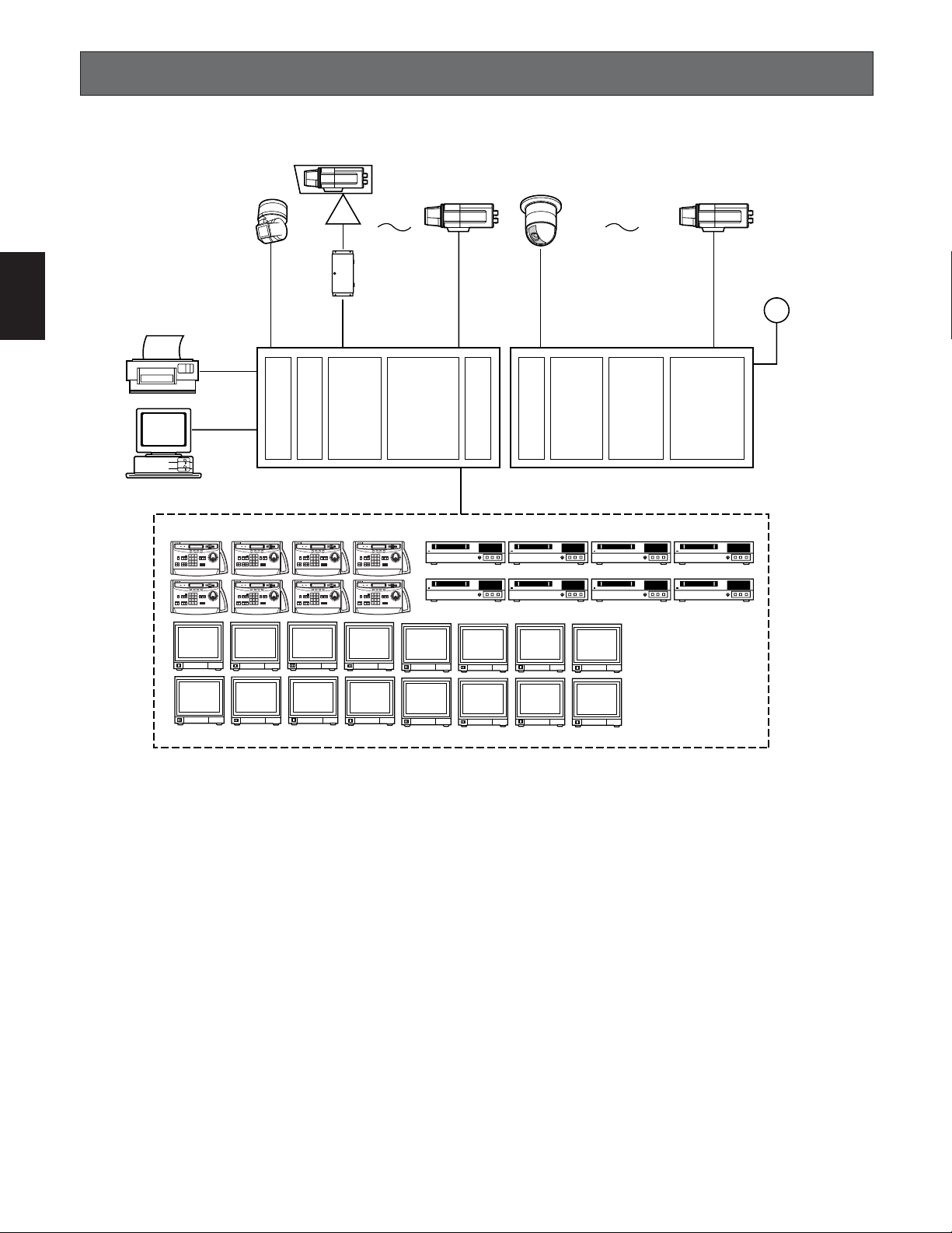
SYSTEM DIAGRAM
Shown below is an example of the expansion capabilities of the WJ-SX550C Matrix Switcher.
TL TL TL TL
TL TL TL TL
CPU
Board
Control
Board
WV-PB5504AE
4ch
Output Board
X4
Ext.
Board
WV-PB5508E
8ch
Input Board
X8
Ext.
Board
WV-PB5564E
Alarm
Board
X2
WV-PB5504AE
4ch
Output Board
X4
WV-PB5508E
8ch
Input Board
X8
Printer
Computer
RS-232C Port
64 Cameras 128 Cameras
128 Alarm Inputs
WV-CU550CJ System Controller (Max 8 Controllers) Max 16 VTR Control Outputs
WJ-SX550C
Matrix Switcher
WJ-AD550
Extension Unit
Video Monitor (Max. 16 Outputs)
System Controller WV-CU CJ
550
1 2 3
4 5 6
7 8 9
0
System Controller WV-CU CJ
550
1 2 3
4 5 6
7 8 9
0
System Controller WV-CU CJ
550
1 2 3
4 5 6
7 8 9
0
System Controller WV-CU CJ
550
1 2 3
4 5 6
7 8 9
0
System Controller WV-CU CJ
550
1 2 3
4 5 6
7 8 9
0
System Controller WV-CU CJ
550
1 2 3
4 5 6
7 8 9
0
System Controller WV-CU CJ
550
1 2 3
4 5 6
7 8 9
0
System Controller WV-CU CJ
550
1 2 3
4 5 6
7 8 9
0
Camera Input: Up to 128 cameras can be connected. The pan/tilt head, zoom /focus/iris of the lens and auxiliary switching
can be controlled via a single coaxial cable through a receiver. Also, preset control of the lens and pan/tilt head position is
possible by using the Combination Camera System.
Monitor Output: Up to 16 monitors can be connected. The camera title, camera and monitor number and alarm condition can
be displayed on the monitor screen.
System Controller: Up to 8 controllers may be connected. A variety of controls are accessible through the LCD display on the
system controller. The System Controller also provides access to the Set Up Menu and Tables for programming.
VTR: Up to 16 VTRs can be connected. The video signal controlled by the WJ-SX550C Matrix Switcher is supplied to the VTR.
Also, the Matrix Switcher can supply the VTRs with an alarm output signal to switch time lapse recording mode.
Alarm Input: Up to 128 alarm signals can be supplied. An Alarm Sensor with a Normally Open or Normally Closed circuit
should be used.
Printer Output: The data programmed on the Setup Menu can be printed out.
RS-232C Port: The system controller can be substituted by connecting a Personal Computer to control the system.
Note: For using a Personal Computer, you will need special software offered separately.
9
1
FEATURES
■ Log-in
To operate the Matrix Switcher System 500, a registered
operator must first supply his/her Operator Number and
Password to the system.
The operator number and password are established by
using the REGISTRATION table. See page 14 for more
details on operator number registration.
If an attempt is made to enter an operator number and
password that do not match with the registered operator
numbers and passwords, entry into this system is denied.
As shown in the examples below, there are 2 additional
attributes associated with an operator: operator level and
priority. These items are described in more detail on page
14.
Operator name: Mike
Operator number: 1
Operator level: 1
Password: 07171
Priority: 1
Operator name: Robert
Operator number: 15
Operator level: 13
Password: 11524
Priority: 8
Notes:
• Factory Default Setting Operator number: 1
Password: 12345
are registered to allow access for first time system
programming.
• An operator can be logged-in to this system from
several system controllers.
• If the main power of the Matrix Switcher is turned
off, log-in procedures must be performed again.
• If power to the system controller is turned off, the
system controller will record operating status when
power is resupplied.
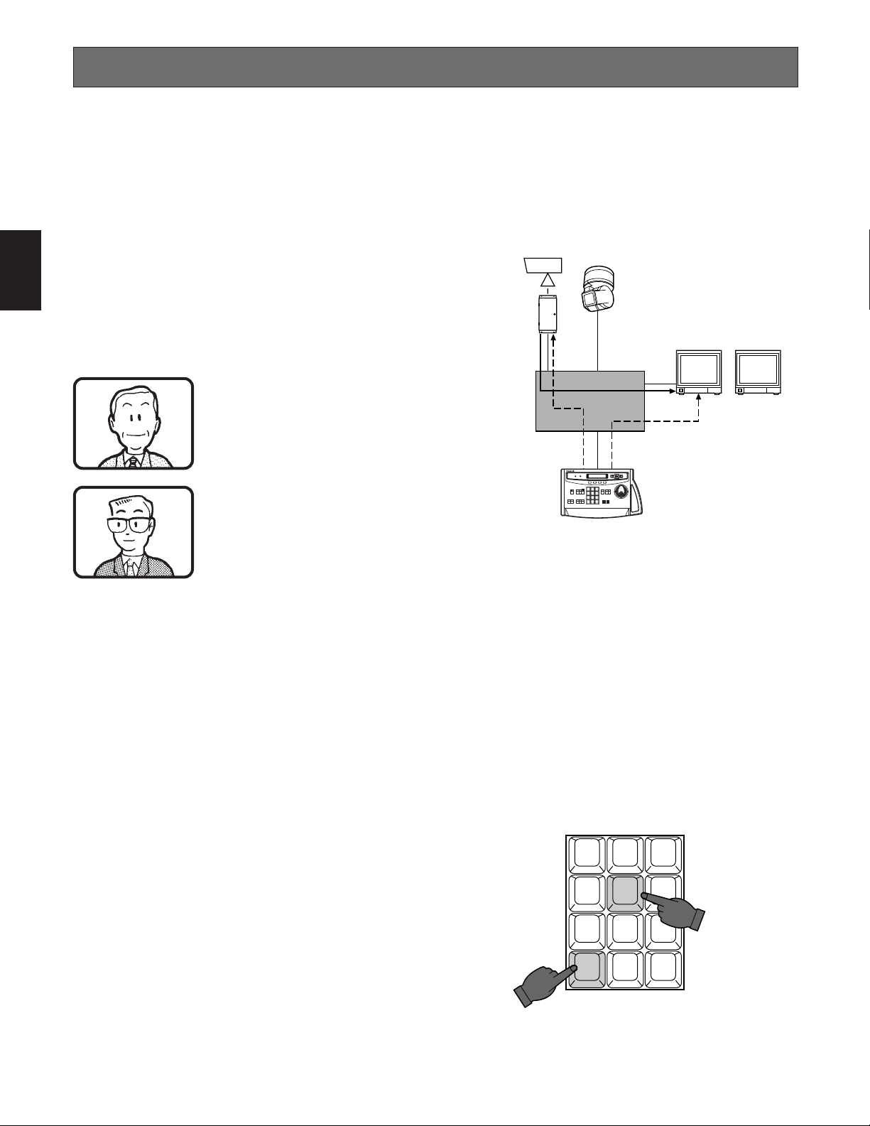
■ Camera and Monitor Selection
After logging in, the desired camera and monitor combina-
tion can be selected.
Basically, any combination of camera and monitor, which
are connected to the Switcher, can be selected as shown
below.
12
3
Camera-1 Camera-2
WV-RC150
Controller
Monitor-1 Monitor-2
WJ-SX550C
System Controller WV-CU CJ
550
1 2 3
4 5 6
7 8 9
0
General Procedures
1. Select the desired monitor. (Monitor and controller
are linked.)
2. Select the desired camera. (Camera and controller
are linked.)
3. The picture of the selected camera view is dis-
played on the selected monitor.
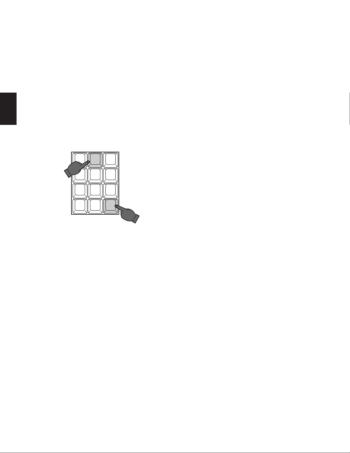
● Monitor Selection
By selecting the monitor with the System Controller, it is
linked with the System Controller.
At this time, the camera output signal that was last supplied
to the monitor is displayed.
Press the Numeric keys (1 to 16), then press the MON
(ESC) key to select the desired monitor.
CAM
ESC SET
123
4 5 6
7 8 9
MON
0
For example: When selecting monitor Number 5:
Press 5, then press the MON (ESC) key.
10
1
Notes: The desired monitor selection may not be avail-
able due to one of the following reasons:
• The System Controller used for selecting a particu-
lar monitor is not allowed access to that monitor
because of controller partitioning.
See page 16 for more details.
• The desired monitor is currently selected by another
operator who has a higher operator priority, and
therefore, control over that monitor.
In this case, “Monitor Busy” or “NOT AVAILABLE”
will be displayed on the LCD Display of the System
Controller.
● Camera Selection
The video signal from the desired camera can be supplied
to the selected monitor.
Press the Numeric keys (1 to 128), then press the CAM
(SET) key to select the desired camera.
2 3
4 5 6
7 8 9
MON CAM
ESC SET
0
1
For example: When selecting Camera Number 2:
Press 2, then press the CAM (SET) key.
Notes: The desired camera selection may not be avail-
able due to one of the following reasons:
• The operator is not allowed access to the desired
camera because the Operator Registration has lim-
ited the operator’s access to certain cameras.
See page 14 for more details.
• The desired camera is currently selected by anoth-
er operator who has a higher operator priority, and
therefore, control over that camera.
In this case, “Camera Busy” will be displayed on
the LCD Display of the System Controller.
■ Camera Site Control
The selected camera (if applicable) can be controlled by
the System Controller.
Specified Panasonic combination cameras can have vari-
ous functions controlled remotely without the need for a
receiver.
Note: Because future camera models may have additional
features and functions, please refer to the Operating
Instructions provided with the camera for more details.
● Lens Focus Control
This control is used to adjust the lens focus to obtain a
sharply focused picture while observing the monitor screen.
● Lens Zoom Control
This control is used to adjust the lens zoom to obtain the
desired picture while observing the monitor screen.
● Lens Iris Control
This control is used to close or open the lens iris to obtain
the proper picture exposure while observing the monitor
screen.
● Pan/Tilt Control
This control is used to pan or tilt the pan/tilt head.
The following operations are available.
• Manual Operation
Using the Joystick Controller to move the Pan/Tilt head
towards the desired direction.
Eight directions are available: UP/DOWN/RIGHT/ LEFT/
UP-RIGHT/UP-LEFT/DOWN-RIGHT/DOWN-LEFT.
• Auto Panning Operation
It is necessary to use a Pan/Tilt head such as the WV-
7225 or specified Panasonic combination camera
equipped with the auto pan feature in a system.
• Random Panning Operation
It is also necessary to use a Pan/Tilt head equipped
with the random panning feature, such as the WV-7225,
in a system.
● Preset Control
The preset function is used to memorize the focus, zoom,
pan and tilt setting values of any scene to have them avail-
able for easy recall at any time.
In addition, if the Camera Position Number is saved with its
associated camera number and preset position, the cam-
era position can be recalled quickly by activating the cam-
era selection and preset function at the same time.
This control is available when the specified camera
equipped with the preset feature is used in a system.
● Auxiliary (AUX) Control
This control is used to turn on or off the user’s auxiliary
switches located in the Receiver, such as the WV-RC100,
WV-RC150 or WV-RC170 Receivers.

11
1
■ Sequence
This system has three kinds of sequential modes: Program, Tour and Group
● Program Sequence
The Program Sequence is a series of 64 steps assigned to a particular monitor.
Each step has a Camera and Dwell Time assigned to it.
In the Program Sequence, each monitor has its own specified sequence operation as shown below.
• Auto Skip Function
The Auto Skip function is available in sequence mode. If there is no video signal present at a step, the sequence will auto-
matically skip that step.
This function is enabled from the Set Up Menu.
• Dwell Time
The amount of time each camera view is displayed on the monitor (Dwell Time) can be set from 1 second to 30 seconds in
1-second increments.
This function is set from the Set Up Menu.
External Timing, which is controlled from the Time Lapse VTR, can also be selected from the Set Up Menu.
Monitor 1
Dwell time: 3 sec.
Step 1
Monitor 1
Dwell time: 3 sec.
Step 2
Monitor 1
Dwell time: 3 sec.
Step 3
Monitor 1
Dwell time: 3 sec.
Step 4
Monitor 1
Dwell time: 3 sec.
Step 5
s
s
s s
s
● Tour Sequence
A Tour Sequence consists of 64 steps.
Each step has a Camera, Dwell Time, Auxiliary Control and Pan/Tilt Preset assigned to it.
A total of 32 Tour Sequences can be programmed on the Set Up Menu.
A Tour can be assigned to any monitor.
Monitor 1
Dwell time: 5 sec.
Step 1
Monitor 1
Dwell time: 3 sec.
Step 2
Monitor 1
Dwell time: 10 sec.
Step 3
Monitor 1
Dwell time: 5 sec.
Step 4
Monitor 1
Dwell time: 3 sec.
Step 5
s
s
s s
s
T1 T2 T3 T4 T5 T6 T7 T8
T9 T10 T11 T12 T13 T14 T15 T16
T17 T18 T19 T20 T21 T22 T23 T24
T25 T26 T27 T28 T29 T30 T31 T32
Tour Sequence
32 Tours to Any Monitor
Monitor 1
Monitor 2
Monitor 3
Monitor 4
Monitor 15
Monitor 16

12
1
● Group Sequence
A Group Sequence consists of up to 64 steps.
In each step, a maximum of 16 cameras can be assigned to 16 monitors.
Pan/Tilt preset and Auxiliary control (1 & 2) can also be set for each camera/monitor combination.
Camera view switching (Dwell Time) for each step can be set from 1 second to 30 seconds in 1-second increments.
There are 8 Group Sequences available, with programming performed on the Set Up Menu.
CAM 13 CAM 14 CAM 15 CAM 16
CAM 9 CAM 10 CAM 11 CAM 12
CAM 5 CAM 6 CAM 7 CAM 8
CAM 1 CAM 2 CAM 3 CAM 4
4th Floor
Group Sequence
C 13 C 14 C 15 C 16
3rd Floor
C 9 C 10 C 11 C 12
2nd Floor
C 6 C 8
1st Floor
C 1 C 2 C 3 C 4
C 5
C 7
Monitor 1 Monitor 2 Monitor 3 Monitor 4
■ Timer Event
The timer function is used to program and automatically activate Tour or Group Sequences according to the time of day, day
of week and 5 user defined special days.
There are 45 timer events available in one day.
■ Alarm Control
● Alarm Input
There are 2 kinds of alarm inputs available in the system.
• Camera Site Alarm
This alarm signal is supplied from the associated camera site receiver or camera.
Receivers capable of camera site alarm input are models WV-RC100, WV-RC150 and WV-RC170.
•Interface Alarm
This alarm signal is supplied from the Alarm Input (ALARM IN) Connector on the optional Alarm Boards installed in the WJ-
SX550C Matrix Switcher.
Up to 128 alarm inputs are available.
• Alarm Operation Modes
There are three alarm operation modes available in the WJ-SX550C Matrix Switcher.
The alarm modes can be switched according to the time programmed on an internal timer.
13
1
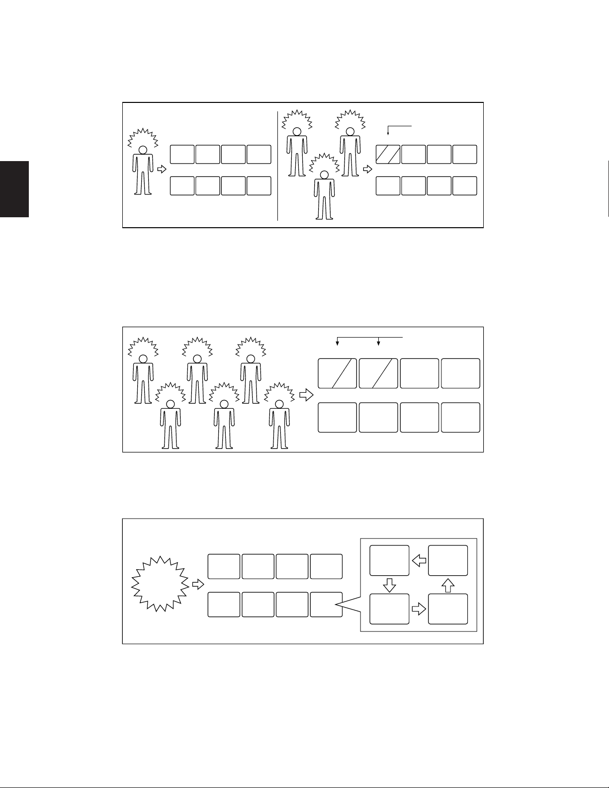
Examples of these modes are described below.
Alarm Mode 1: Any alarmed pictures are assigned to Monitor 1.
Mode 1 displays all alarms on Monitor 1.
If more than one alarm is activated, the system will sequentially display the alarms on Monitor 1.
A
1
A
2 3 4
5 6 7 8
Alarm
A
1 2 3 4
5 6 7 8
A
Alarm
C
Alarm
B
Alarm
B
C
Monitors Monitors
Sequence
Alarm Mode 2: Any alarmed pictures are assigned to four Monitors (1 - 4).
Mode 2 displays the first alarm on Monitor 1.
When the second alarm is received, the first alarm is shifted to Monitor 2 and the second alarm is displayed on Monitor 1
and so on.
This means, the latest alarm is always displayed on Monitor 1.
If more than four alarms are activated, the system will sequence the pictures starting with Monitor 1, then 2, etc.
A
Alarm
A
1 2 3 4
5 6 7 8
B
Alarm
E
C
Alarm
E
Alarm
D
Alarm
F
Alarm
B
F
CD
Sequence
Monitors
Alarm Mode 3: Any alarmed pictures are assigned to any monitors.
Mode 3 is a fully programmable mode. Any alarm can be shown on any monitor, plus sequence routines, presets and aux-
iliary relays in receivers can be activated.
1 2 3 4
5 6 78
ANY
Alarm
WZ
XY
Any sequence, preset and auxiliary control
Any monitors
● Alarm Recall
The WJ-SX550C Matrix Switcher can store up to 99 Alarm Logs in its memory.
The alarms may be recalled and displayed in chronological order on any desired monitor.

14
1
34341 3221332132
Level 3
12123
Level 1
OPE-1
1
OPE-5 OPE-6 OPE-7
12341 1244312243
Level 2
OPE-2 OPE-3 OPE-4
43432 4333142341
Level 4
OPE-8~OPE-26 OPE-27
54343 5656754543
Level 5
OPE-28 OPE-29 OPE-30
Priority
2
3
4
5
6
7
8
26
27
28
29
30
Operator LEVEL TABLE
MENU
CAMERA TITLE
TIMER
PROG SEQ
TOUR SEQ
GRP SEQ
PRESET
ALARM
KEY BOARD
OPERATOR
COMP/VD2
CLOCK
CAM SELECT
P-SEQ SELECT
T-SEQ SELECT
G-SEQ SELECT
ALARM ACK/RST
MENU
CAMERA TITLE
TIMER
PROG SEQ
TOUR SEQ
GRP SEQ
PRESET
ALARM
KEY BOARD
CAM SELECT
P-SEQ SELECT
T-SEQ SELECT
G-SEQ SELECT
ALARM ACK/RST
CAM SELECT
P-SEQ SELECT
T-SEQ SELECT
G-SEQ SELECT
ALARM ACK/RST
CAM SELECT
P-SEQ SELECT
T-SEQ SELECT
G-SEQ SELECT
CAM SELECT
P-SEQ SELECT
T-SEQ SELECT
~
■ Operator Registration
On the Operator Registration tables, an operator’s level, priority, password and camera access limits can be programmed.
Up to 30 operators may be registered.
For example:
● Level Setting
Operator access to various setup functions and system operations is determined by the operator’s level.
There are five separate levels available (Level 1 is the highest).
● Priority
When two or more operators attempt to perform the same function at the same time, the operator with the higher priority is
allowed to perform the function while the lower priority operators’ attempts are denied.
There are 30 priority levels available in this system.
● Password
All operators have a five digit long password assigned to them.
● Operator Limits for Camera Access
Access to any camera’s video and control of the camera’s pan/tilt head may be restricted to certain operators.
15
1
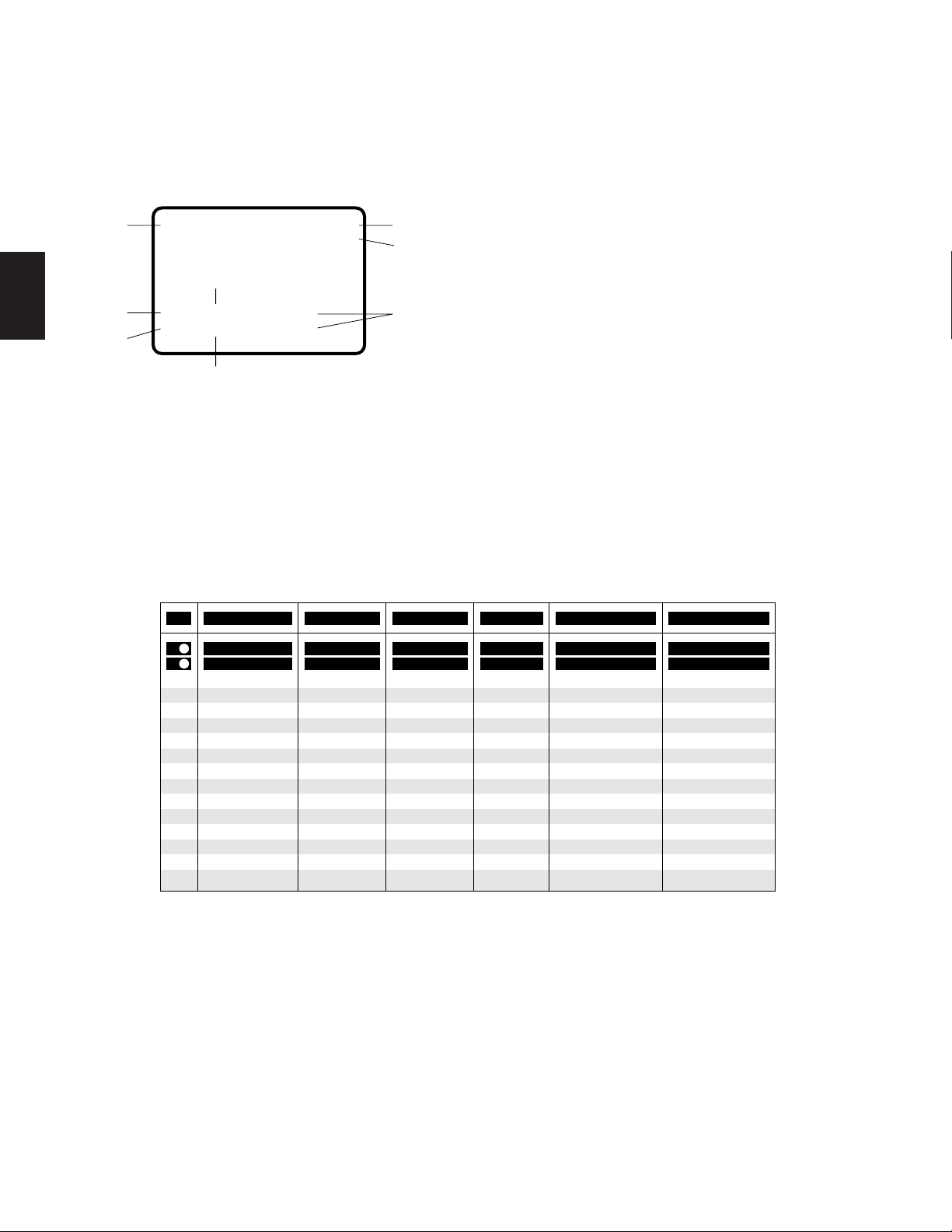
■ Camera Title and On-screen Display
A camera title for each camera input is available for display on the monitor screen.
Each title is composed of 15 characters per line, times 2 lines.
All items listed below, except Alarm On/Off and Timer mode, can be included or excluded from display on the selected moni-
tor screen.
07 MAY '00 14:23:56 AL1
/T32
C 01 M16 3rd Floor
Pr64 T32 Room 306
qw
e
i
u
t
r
y
q Date and Time
w Alarm On/Off
AL0: Camera Site Alarm
AL1: Interface Alarm
e Timer Mode
r Camera Number
t Monitor Number
y Preset Position Number
u Sequence Mode in Effect
i Camera Title
Note: When the overscanning mode is selected on a monitor, the screen display (edge portion) may be partially hidden.
■ System Status Display
This table shows the system status in real time.
Possible Active modes, as indicated in this table, are defined below.
AL
02
03
05
06
07
08
09
10 in
11
12
13
14
15
16
04
Monitor Camera CTRLR Operator Priority
01
00
01
03
03
02
02
02
11
02
26
01
05
Mode
11
21
T 1
09
48
63
10
03
35
09
49
53
49
26
01 F
SPOT
T08F
G2S
G2S
G2S
CAM
SPOT
T64F
SPOT
T11F
G1B
G1B
G1B
SPOT
SPOT
2
8
4
17
30
51
10
SPOT : Spot
P: Program Sequence
T: Tour Sequence
G: Group Sequence
CAM : Camera Setting
SET : Setup
in : Displays video connected to the Video
Output Board
F: Forward Sequence
B: Backward Sequence
S: Paused
16
1
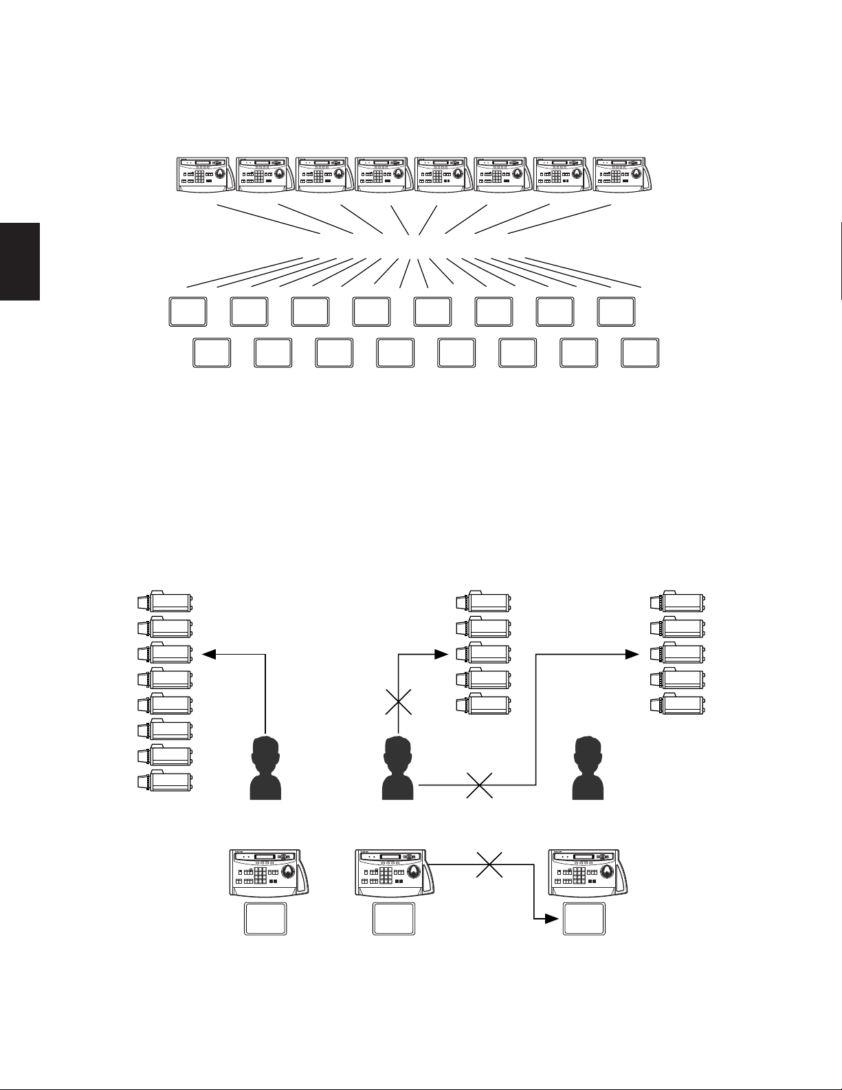
■ System Controller-Monitor Partitioning
This feature is used to prevent specific WV-CU550CJ System Controllers from controlling the outputs of specific monitors.
It prevents an operator from unintentionally gaining control over a monitor that may not be associated with his/her station.
12345678
M1 M3 M5 M7 M9 M11 M13 M15
M2 M4 M6 M8 M10 M12 M14 M16
System Controller Partitioning To Monitors
WV-CU550CJ
System Controller WV-CU CJ
550
1 2 3
4 5 6
7 8 9
0
System Controller WV-CU CJ
550
1 2 3
4 5 6
7 8 9
0
System Controller WV-CU CJ
550
1 2 3
4 5 6
7 8 9
0
System Controller WV-CU CJ
550
1 2 3
4 5 6
7 8 9
0
System Controller WV-CU CJ
550
1 2 3
4 5 6
7 8 9
0
System Controller WV-CU CJ
550
1 2 3
4 5 6
7 8 9
0
System Controller WV-CU CJ
550
1 2 3
4 5 6
7 8 9
0
System Controller WV-CU CJ
550
1 2 3
4 5 6
7 8 9
0
For example:
The following example demonstrates the use of both system controller-monitor partitioning and operator priority.
• Camera: 8 sets
• Monitor: 3 sets
• System Controller: 3 sets
• Operator : 3 persons
Setting Procedure
1. Operator Number 1 has the first priority . Cameras 1-8 can be selected by Monitor 1.
2. Operator Number 2 has the second priority. Cameras 1-5 can be selected by Monitor 2 (limited access due to operator
partitioning).
3. Operator Number 3 also has the second priority. Cameras 4-8 can be selected by Monitor 3.
1
2
3
4
5
6
7
8
1
2
3
4
5
4
5
6
7
8
M1
SPOT
Controller 1
Operator 1
Priority 1
M2
SPOT
Controller 2
Operator 2
Priority 2
M3
SPOT
Controller 3
Operator 3
Priority 2
Controller
Partitioning
Operator's
Partitioning
Operator's
Priority
System Controller WV-CU CJ
550
1 2 3
4 5 6
7 8 9
0
System Controller WV-CU CJ
550
1 2 3
4 5 6
7 8 9
0
System Controller WV-CU CJ
550
1 2 3
4 5 6
7 8 9
0
1. In the above system, when Operators 1 and 2 both select camera 3 simultaneously, the selection of Operator 1 is allowed
because Operator 1 has a higher priority.
2. Operator 2 can not select camera 6 because operator’s partitioning limits access to cameras 1-5 by Operator 2.
3. Operator 2 can not control Monitor 3 because controller partitioning prevents access to monitor 3 by Operator 2.

17
1
■ Synchronizing the Sequence
with External Timing
The camera switching interval (Sequence Dwell Time) can
be synchronized with the time lapse mode set in the associ-
ated Time Lapse VTR.
Select the On or Off mode on the EXT Timing Select table to
meet each monitor’s requirements.
Caution: Set the interval time for the external timing signal
of the external equipment to 1 second or more.
If the interval is set to less than 1 second, the system
will not work properly.
■ Cable Compensation/VD2
Cable Compensation
This feature is used to compensate for signal loss due to
cable length.
The most suitable position for cable-loss compensation can
be selected in the Set Up Menu.
Available cable length compensations are shown
below.
S: Up to 500 m (1 600 ft)
M: 500 m (1 600 ft) to 900 m (2 900 ft)
L: 900 m (2 900 ft) to 1 200 m (4 000 ft)
(When using RG-6/U or equivalent)
VD2 (V ertical Drive Sync Signal)
The VD2 (Vertical Drive Sync Signal) can be turned On or
Off by using the Set Up Menu.
Select VD2 On or Off to meet camera requirements.
■ RS-485 Site Communication
The parameters for communication with the Camera Site
can be set on the RS-485 Site Communication table in the
Set Up Menu, if the optional WV-PB5548E Data Board is
installed in the Matrix Switcher.
(The WV-RM70 Camera Controller or a modem may be
required in the system.)
Note: Be sure to select the correct Baud rate when using a
modem.
■ Clock
On-screen clock display is available.
The date and time can be set on the Clock Set table.
■ Printer
A parallel printer can be used to print out the Status, Alarm
Recall or Setup data.
The recommended printer to use is the Panasonic KX-
P1624 Impact Dot Matrix Printer.
■ RS-232C Port
This port is used for connecting with a Personal Computer.
The memory of the WJ-SX550C Matrix Switcher can be
loaded or saved.
A Personal Computer can be substituted for the WV-
CU550CJ System Controller to control the system.
Note: For using a Personal Computer, you will need special
software offered separately.

19
2
SECTION 2
DETAILED
PRODUCT DESCRIPTION
AND SELECTION
20
2
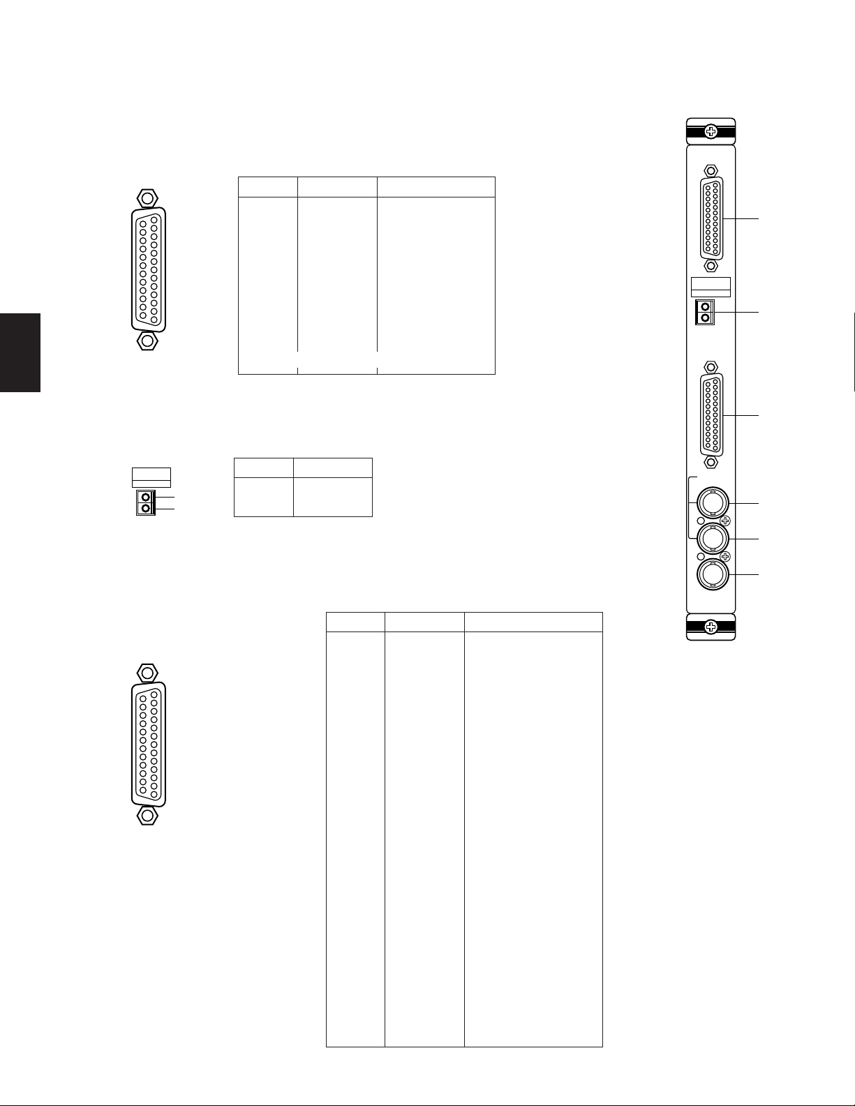
● Rear View
MAJOR OPERATING CONTROLS AND THEIR FUNCTIONS
WJ-SX550C Matrix Switcher
■ Appearance
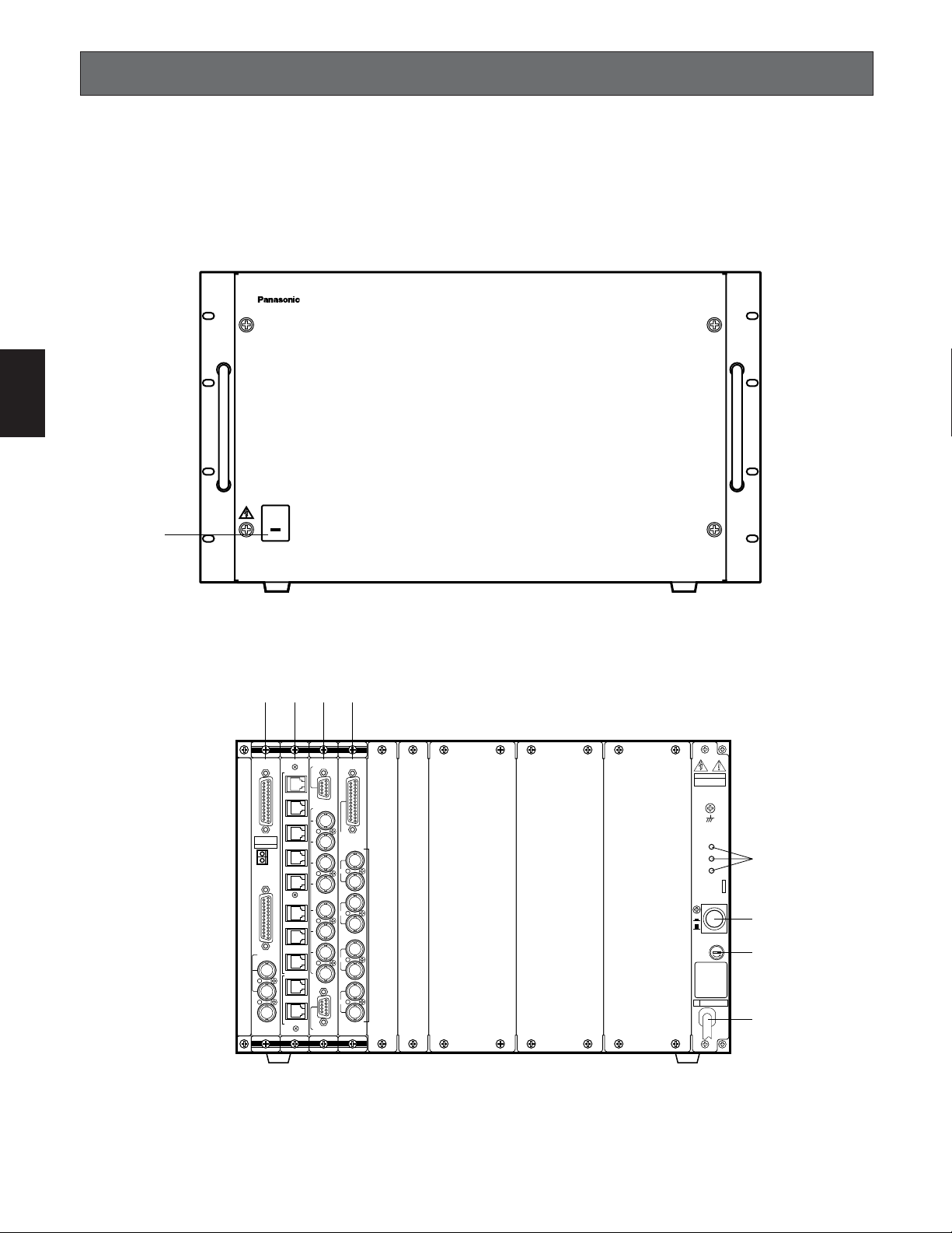
● Front View
OPERATE
Matrix Switcher WJ-SX
550C
q
CPU
RS-232C
TIME
ADJUST IN
COM
PRINTER
OUT
IN
VS/VD
VD
OUT
OFF
+9V
+5V
−5V
POWER
ON
11A00001
INPUT
1
2
3
4
5
6
7
8
CAMERA IN
VIDEO OUT1
VIDEO OUT2
CONTROL
DATA 1
DATA 2
OUT
IN
1
OUT
IN
2
OUT
IN
3
OUT
IN
4
MONITOR
ALARM OUT
RESET OUT
EXT TIMING IN
RECOVER IN
OUTPUT
CAUTION
DATA 3
DATA 4
DATA 5
DATA 6
DATA 7
DATA 8
DATA 1
DATA 2
wert
y
u
i
o

21
2
q Operate Indicator (OPERATE)
Is on when the power of the WJ-SX550C Matrix
Switcher is turned on.
w CPU Board (CPU)
A personal computer and printer can be connected to
this board.
Refer to the CPU Board on page 22 for more details.
e Control Board (CONTROL)
The system controllers can be connected to this board.
Refer to the Control Board on page 25 for more details.
r Video Input Board (INPUT)
The cameras and receivers are connected to this
board.
Refer to the Video Input Board on page 27 for more
details.
t Video Output Board (OUTPUT)
The video monitors can be connected to this board.
Refer to the Video Output Board on page 29 for more
details.
y Voltage Indicator (+9V, +5V, –5V)
These LEDs indicate the presence of +9 V, +5 V and
–5 V regulated DC voltages.
u Power Switch (POWER ON/OFF)
This switch is used to turn the Matrix Switcher power on
and off.
i Fuse Holder
o AC Power Cord
22
2
Pin No.
Printer ← Switcher
Printer ← Switcher
Printer ← Switcher
Printer ← Switcher
Printer ← Switcher
Printer ← Switcher
Printer ← Switcher
Printer ← Switcher
Printer ← Switcher
Printer → Switcher
Printer → Switcher
Monitor ← Switcher
Monitor ← Switcher
Monitor ← Switcher
Monitor ← Switcher
Printer ← Switcher
CPU
RS-232C
TIME
ADJUST IN
COM
PRINTER
OUT
IN
VS/VD
VD
OUT
q
w
e
r
t
y
w Time Adjustment Input Connector (TIME ADJUST IN)
Accepts the time adjustment signal from a Time Lapse VTR. It enables the time display of the
WJ-SX550C Matrix Switcher and the Time Lapse VTR to be matched.
■ CPU Board
● Appearance
q RS-232C Port (RS-232C)
This port is used to connect a personal computer that can store or load the memory in the WJ-
SX550C Matrix Switcher. This port also enables control of the Matrix Switcher with a personal
computer substituted for the WV-CU550CJ System Controller (by using optional software).
Pin No. Designation Direction
1
2
3
4
5
6
7
8
20
(FG)
SD
RD
RS
CS
DR
SG
CD
ER
PC → Switcher
PC ← Switcher
PC → Switcher
PC ← Switcher
PC ← Switcher
PC ← Switcher
PC → Switcher
Other pins are not used.
25
13
1
14
Designation
1
2
Signal
Ground
TIME
ADJUST IN
COM
1
2
e Printer Port (PRINTER)
This port is used to connect a parallel printer which can provide a print out of the System
Status, Alarm Recall or Setup operation data.
Pin No. Designation Direction
1
2
3
4
5
6
7
8
9
10
11
12
13
14
15
16
17
18
19
20
21
22
23
24
25
/STROBE
DATA 0
DATA 1
DATA 2
DATA 3
DATA 4
DATA 5
DATA 6
DATA 7
/ACK
BUSY
(R)
(G)
(B)
(SYNC)
/PRIM
Not used
Not used
Ground
Ground
Ground
Ground
Ground
Ground
Ground
25
13
1
14
Note: If a printer is not used in the sys-
tem, pins 12-15 may be used for
displaying the system status on the
monitor screen (RGB type input).

23
2
r VS/VD Input Connector (VS/VD IN)
Accepts either the VD (Vertical Drive) pulse or the VS (Video Sync) signal for synchronizing the system.
Notes:
• This input is looped through to the VS/VD Output Connector.
• When the VD (or VS) signal is supplied to the VS/VD Input Connector, turn the VD/VS selection switch (SW4) on the cir-
cuit board to the VD (or VS) position. The factory default setting of the VD/VS selection switch (SW4) is VS. Ask quali-
fied service personnel about setting up this switch.
• The external sync signal should meet CCIR specifications and should not contain any jitters, such as a VTR playback
signal.
t VS/VD Output Connector (VS/VD OUT)
Outputs either the VD (Vertical Drive) pulse or the VS (Video Sync) signal for synchronizing other system components.
Note: The input at the VS/VD Input connector is looped through to this output. These inputs and outputs are connected
internally.
y VD Output Connector (VD OUT)
Outputs VD (Vertical Drive) pulses for synchronizing other system components.
Notes:
• The internal VD pulse or the loop-through external VD pulse is provided at this connector.
• When the VS signal is supplied to the VS/VD Input Connector, the VD output signal from the VD Output Connector
will be delayed by approximately 15 µs with respect to the V-sync of the VS input signal.
3H V
VD output signal
VS input signal
approx. 15 µ sec
By changing the position of jumper connector (CN14) on the board, this connector can be used for displaying the system
status on the monitor screen. (Set Up Menu is displayed during setup mode.)
This board should be installed in the WJ-SX550C Matrix Switcher even if the WJ-AD550 Extension Unit is used.
Caution
24
2
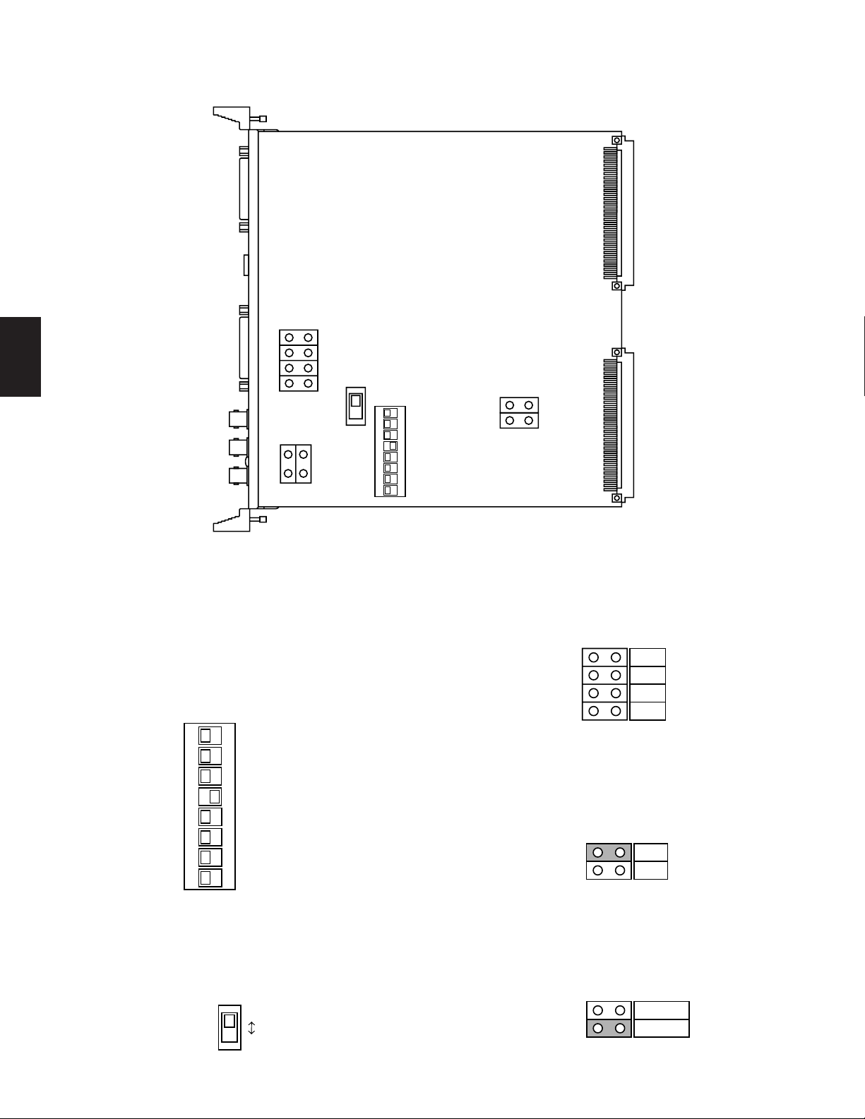
● Board Setting
Before installing this board, the following settings should be made by qualified service personnel or system installers.
CN13
CN12
SW4
CN14
1234
OFF
5678
SW2
1. Confirm that Switches (SW2) on the board are set as
follows.
Note: These switches are used only for factory test.
Always keep these switches in the positions below
in the field.
1234
OFF
SW2
5678
2. Set switch (SW4) on the board to select either VD or VS
for the Sync input signal, if applicable.
The factory default setting is VS.
SW4
SW4
VS
VD
3. Position jumper connectors (CN12) on the board to
open connection position when a printer is connected
to the board.
R
B
G
SYNC
CN12
4. Position jumper connector (CN13) on the board to the
“C/L” position when the setup menu tables are not
clearly displayed on the colour monitor.
The factory default setting is “B/W”.
CN13
B/W
C/L
CN13
5. Position jumper connector (CN14) on the board to
select either VD Output or Status Display Output for the
VD Output Connector.
The factory default setting is VD.
CN14
GRAPHIC
VD
CN14
25
2
Pin No.
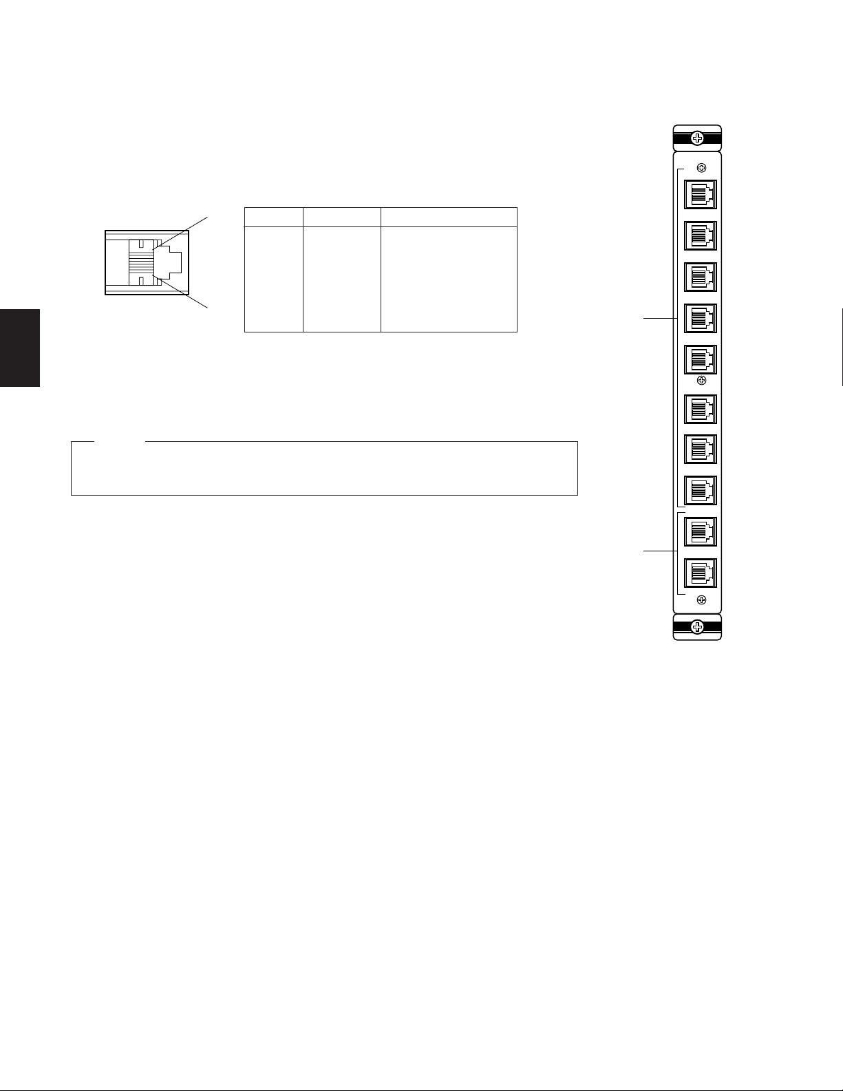
■ Control Board
● Appearance
q Data Ports (DATA 1 - 8)
For exchanging control data with the WV-CU550CJ System Controller. Eight ports are
available on the board. Connect supplied 6-conductor modular cable or use a data
grade shielded 4-wire twisted pair cable suitable for RS-485 communication. Cable
length may be extended up to 1 200 m (4 000 ft).
6
1
Designation Direction
1
2
3
4
5
6
Ground
RB
RA
TB
TA
Ground
Switcher ← Controller
Switcher ← Controller
Switcher → Controller
Switcher → Controller
CONTROL
DATA 1
DATA 2
DATA 3
DATA 4
DATA 5
DATA 6
DATA 7
DATA 8
TEST 1
TEST 2
q
w
w Test Ports (TEST 1, 2)
These ports are used only for factory test.
This board should be installed in the WJ-SX550C Matrix Switcher even if the WJ-AD550
Extension Unit is used.
Caution

26
2
1234
OFF
SW2
CN13
● Board Setting
Before installing this board, the following settings should be made by qualified service personnel or system installers.
1234
OFF
SW2
1. Confirm that switches (SW2) on the board are set as follows.
2. Position jumper connector (CN13) on the board as shown below.
Open: When the controllers are connected in a “Home Run” connection.
Closed: When the controllers are connected in a “Daisy-Chain” connection.
The factory default setting is Open.
CN13
CN13
Open Closed
Note: These switches are used only for factory test.
Always keep these switches in the “OFF” positions in the field.
27
2
Pin No.
■ WV -PB5508E V ideo Input Board
● Appearance
q Video Output Ports (VIDEO OUT 1, 2)
The video signal connected to the Camera Input Connector (CAMERA IN) is present at these
ports.
The camera control data multiplexed on the video signal is not available at these ports. When
the power of the Matrix Switcher is turned off, no signal is present at these ports.
BNC female connectors are available for conversion by use of optional WV-CA64 loop
through cable.
INPUT
1
2
3
4
5
6
7
8
CAMERA IN
VIDEO OUT1
VIDEO OUT2
q
w
9
8
7
6
5
4
3
2
1
1
2
3
4
5
6
7
8
9
Not used
CH1
Ground (CH1)
CH2
Ground (CH2)
CH3
Ground (CH3)
CH4
Ground (CH4)
Not used
CH5
Ground (CH5)
CH6
Ground (CH6)
CH7
Ground (CH7)
CH8
Ground (CH8)
VIDEO OUT
1
VIDEO OUT
2
w Camera Input Connector (CAMERA IN, 1 - 8)
These connectors accept either a colour or B/W composite video signal from a camera.
In addition, the VD2 signal for synchronizing the vertical timing of the cameras, and data to
control camera site devices are multiplexed through this connector.

Camera
In No.
Board
No.
28
2
1234
OFF
SW 1
● Board Setting
Before installing this board, the following setting should be made by qualified service personnel or system installers.
Set switches (SW1) on the board to designate the camera input board number as shown in the following table.
The factory default setting is Board Number 1.
1234
OFF
1234
OFF
1234
OFF
1234
OFF
1234
OFF
1234
OFF
1234
OFF
1234
OFF
1234
OFF
1234
OFF
1234
OFF
1234
OFF
1234
OFF
1234
OFF
1234
OFF
1234
OFF
1
2
3
4
5
6
7
8
9
10
11
12
13
14
15
16
1-8
9-16
17-24
25-32
33-40
41-48
49-56
57-64
65-72
73-80
81-88
89-96
97-104
105-112
113-120
121-128
SW1 Setting
• Board Numbers 9 to 16 are only used when the WJ-
AD550 Extension Unit is used.
• Board Numbers 1 to 8 should be installed in the WJ-
SX550C Matrix Switcher and Board Number 9 to 16 in
the WJ-AD550 Extension Unit.
Do not install more than 9 boards in the WJ-SX550C
Matrix Switcher.
Cautions
29
2
Pin No.
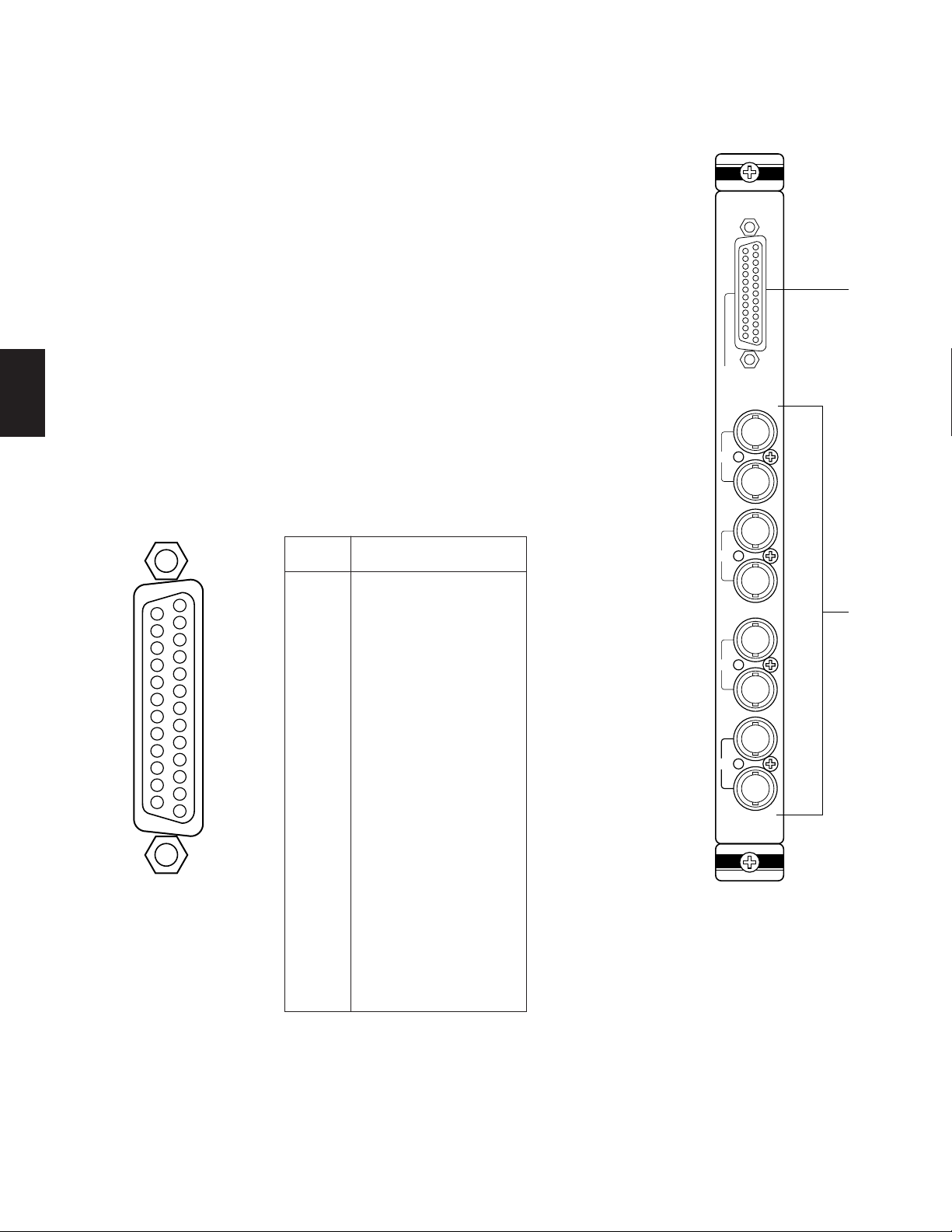
■ WV -PB5504AE V ideo Output Board
● Appearance
q Alarm Output/Reset Output Connector (ALARM OUT/RESET OUT)
External Timing Input Connector (EXT TIMING IN)
Recover Input Connector (RECOVER IN)
ALARM OUT: When the Matrix Switcher receives an alarm from the WV-PB5564E
Alarm Board or camera site receivers WV-RC100, WV-RC150 or WV-RC170, the
alarm output signal is provided at this connector for the Time Lapse VTR.
The active pin number of the alarm output depends on the alarm mode set by the
on-screen program (Mode-1, Mode-2, Mode-3).
RESET OUT: When the Matrix Switcher resets the activated alarm, the alarm reset out-
put signal, either Open Collector or pulse, is provided at this connector for the Time
Lapse VTR.
EXT TIMING IN: The camera switching interval (Sequential Dwell Time) can be syn-
chronized with the lapse mode set on the Time Lapse VTR.
EXT. TIMING IN 1 controls Monitor 1 output, EXT. TIMING IN 2 controls Monitor 2
output, etc.
Supply the camera switching pulse from the Time Lapse VTR to this connector.
Minimum duration for camera switching pulse needs to be one (1) second or more.
RECOVER IN: This connector accepts the alarm recover signal from the Time Lapse
VTR.
OUT
IN
OUT
IN
OUT
IN
OUT
IN
MONITOR
ALARM OUT
RESET OUT
EXT TIMING IN
RECOVER IN
OUTPUT
1
2
3
4
q
w
w Monitor Input/Output Connector (MONITOR IN/OUT)
OUT: Outputs the video signal selected by the Matrix Switcher for the video monitor.
IN: This connector is used for video input from a VTR or for expanding the system to
128 camera inputs.
25
13
24
23
22
21
20
19
18
17
16
15
14
12
11
10
9
8
7
6
5
4
3
2
1
Designation
1
2
3
4
5
6
7
8
9
10
11
12
13
14
15
16
17
18
19
20
21
22
23
24
25
ALARM OUT 1
RESET OUT 1
RECOVER IN 1
Ground
EXT TIMING IN 1
Ground
ALARM OUT 2
RESET OUT 2
RECOVER IN 2
Ground
EXT TIMING IN 2
(+5V DC)
ALARM OUT 3
RESET OUT 3
RECOVER IN 3
Ground
EXT TIMING IN 3
Ground
ALARM OUT 4
RESET OUT 4
RECOVER IN 4
Ground
EXT TIMING IN 4
Ground
Ground
30
2
Monitor
Out No.
SW1 Setting
Board
No.
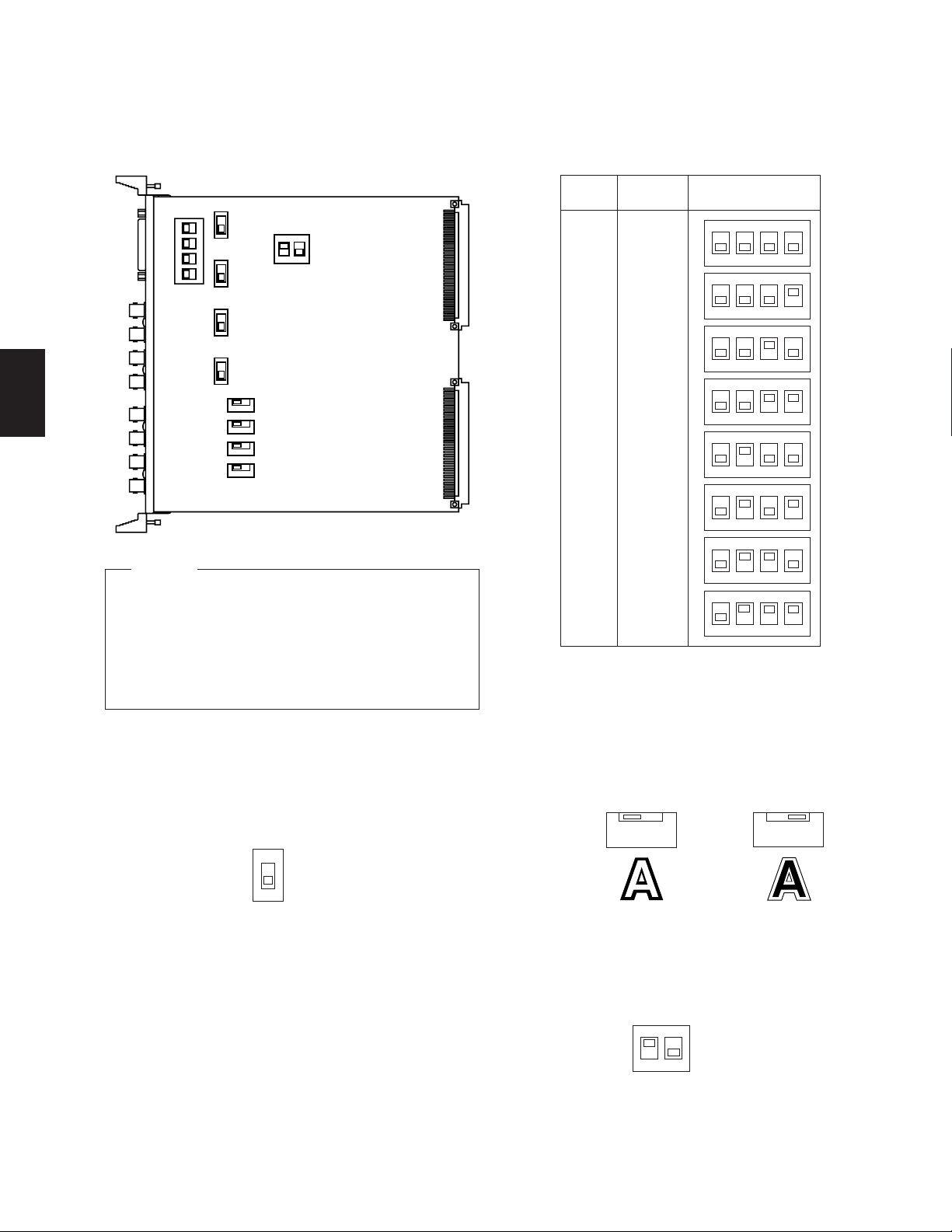
● Board Setting
Before installing this board, the following settings should be made by qualified service personnel or system installers.
1. Set switches (SW1) on the board to designate the monitor output board number as shown in the following table.
The factory default setting is Board Number 1.
1234
OFF
SW1
SW4
SW5
SW3
SW2
12
OFF
SW6
SW100
SW150
SW200
SW250
1234
OFF
1234
OFF
1234
OFF
1234
OFF
1234
OFF
1234
OFF
1234
OFF
1234
OFF
1
2
3
4
5
6
7
8
1-4
5-8
9-12
13-16
1-4
5-8
9-12
13-16
• Board Numbers 5 to 8 are only used when the WJ-
AD550 Extension Unit is used.
• Board Numbers 1 to 4 should be installed in the WJ-
SX550C Matrix Switcher and Board Number 5 to 8 in
the WJ-AD550 Extension Unit.
Do not install more than 5 boards in the WJ-SX550C
Matrix Switcher.
Cautions
2. Set switches (SW2/SW3/SW4/SW5) on the board to
meet the alarm reset output requirement as either Open
Collector (OPEN C.) or Pulse (VTR).
The factory default setting is Pulse (VTR).
Open Collector (OPEN C.): 16 V DC 100 mA max.
Pulse (VTR): +5 V DC approx. 500 ms
Note: Be careful when setting these switches as the
switches are not physically located on the board in
numerical order.
Switch location from the top of the board, going
downward, is: SW4 (reset out 3), SW5 (reset out 4),
SW3 (reset out 2) and SW2 (reset out 1).
CH1
OPEN C
VTR
3. Set switches (SW100/SW150/SW200/SW250) on the
board to meet the character display requirement on the
monitor screen.
The factory default setting is normal (NOR).
NOR: White with Black Border
REV: Black with White Border
4. Confirm that switches (SW6) on the board are set as fol-
lows.
NOR REV
NOR REV
NOR Position
REV Position
PAL TEST
NOR
SW6
NTSC
OFF
12
Note: These switches are used only for factory test.
Always keep these switches in the positions
above in the field.
31
2
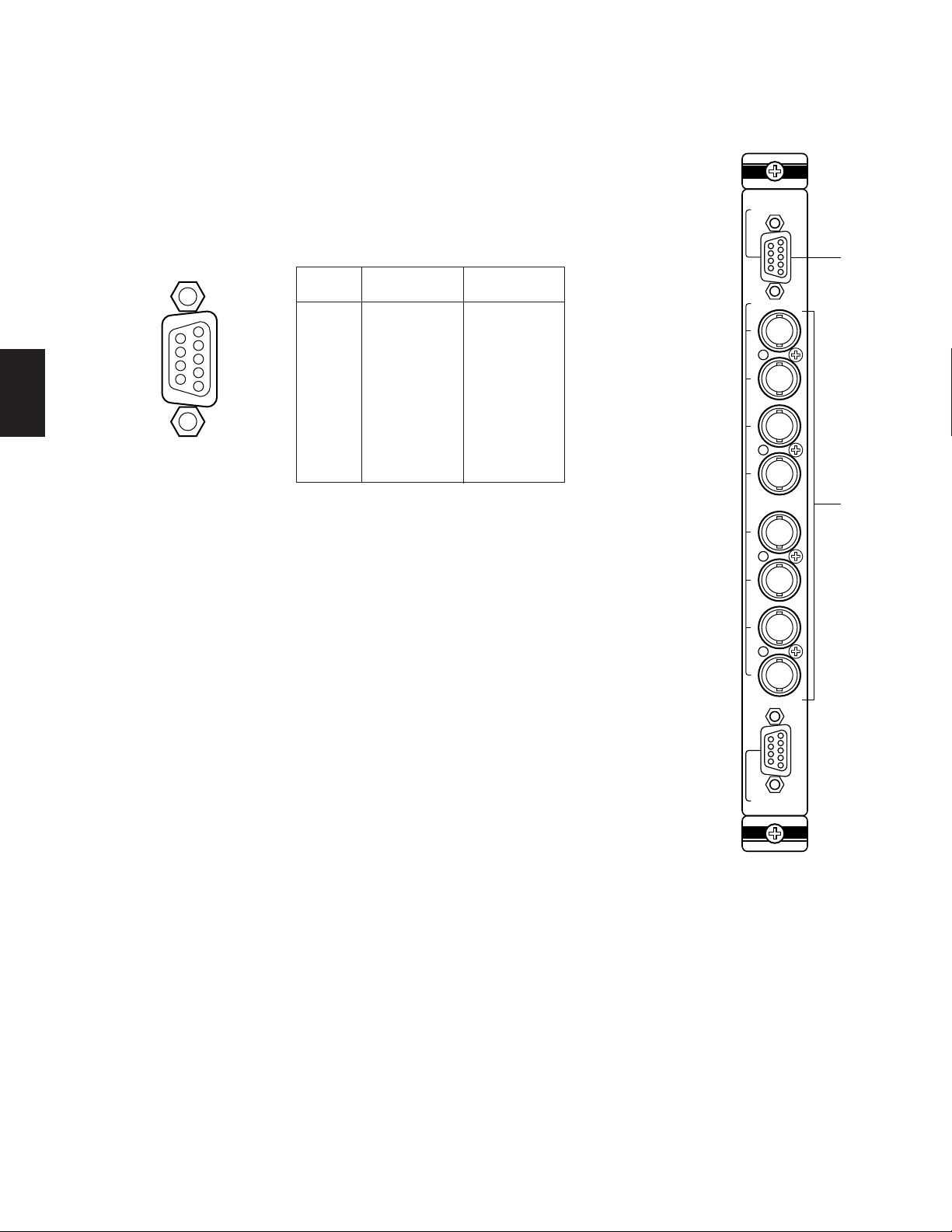
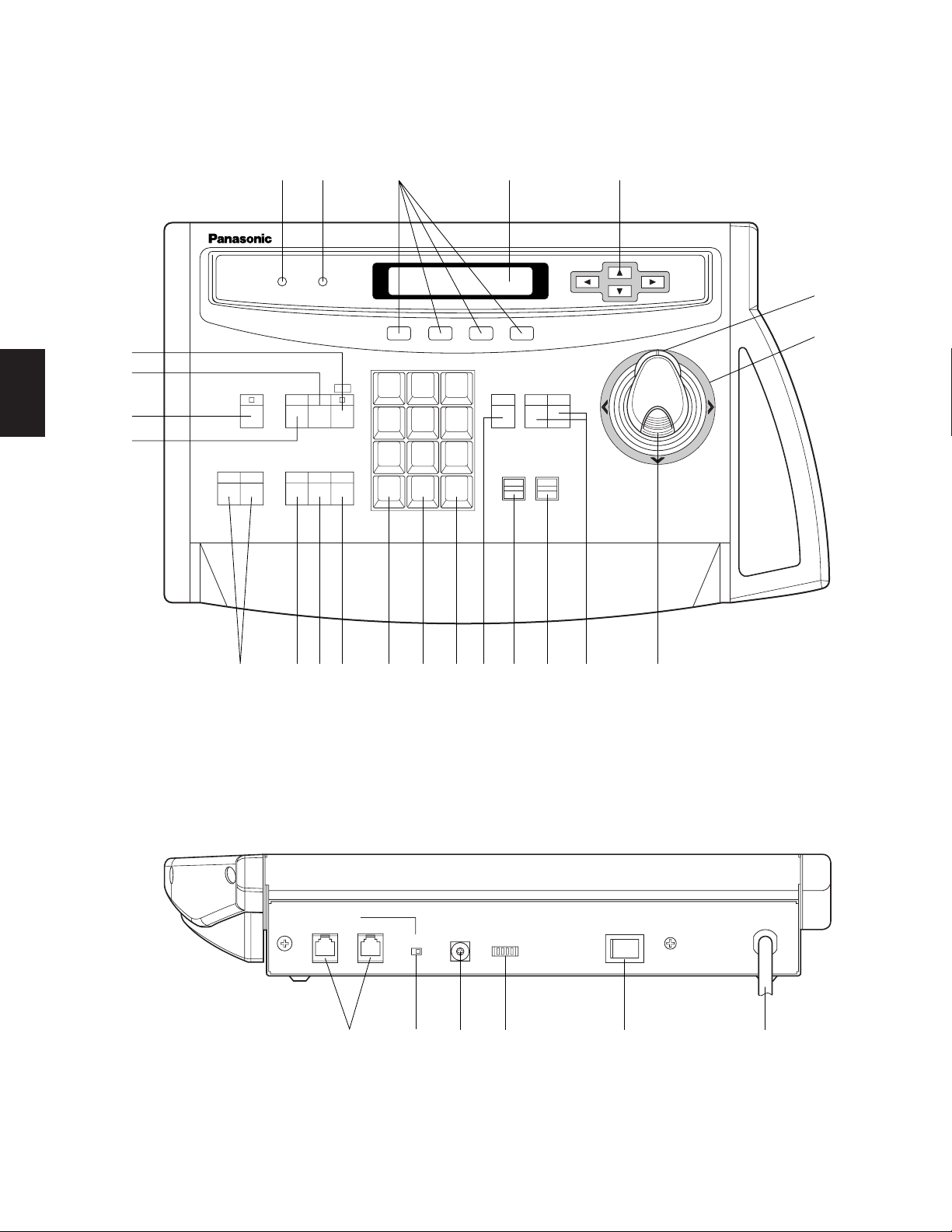
WV -CU550CJ System Controller
■ Appearance
● Front View
● Rear View
System Controller WV-CU CJ
550
ALARM
BUSY
F1 F2
SET
WIDE
AF
ZOOM
TELE
ESC
SLOW
ALT
BACK
SEQ
ACK
RESET
FORWARD
SEQ
DEC
-1CAM
AUX
INC
+1CAM
STOP
21
F3 F4
1 2
3
4
5 6
7
8 9
MON
0
CAM
CLOSE
OPEN
IRIS
PRESET
FAR
FOCUS
NEAR
q w r t
y
i!0!3!4!5!6!7!8!9
@2
!1!2 o
e
u
@3
@1
@0
CONTROLLERCONTROLLER
UNIT No.
1-8
MODE
DATA
TERM.
ON
ON
OUT
OFF
OFF
IN
5
4
3
2
1
0
9
8
7
6
@4 @5 @6 @7 @8 @9
Loading...