


INSTALLATION INSTRUCTIONS
Mini VRF System Air Conditioner
This air conditioner uses the refrigerant R410A.
NOTE External diameter of service port R410A: 5/16"
Model No.
Outdoor Units |
|
|
|
|
|
|
|
|
|
|
|
||
Type |
Outdoor Unit Type |
|
36 |
|
|
52 |
|
|
|
|
|
||
|
|
|
|
|
|
|
|
|
|
|
|
|
|
U |
Mini VRF System |
U-36LE1U6 |
|
U-52LE1U6 |
|
|
|
|
|||||
|
|
|
|
|
|
|
|
|
|
||||
U-36LE1U6E* |
|
U-52LE1U6E* |
|
|
|
|
|||||||
|
|
|
|
|
|
|
|
|
|||||
|
|
|
|
|
|
|
|
|
|
|
|
|
|
* Salt-Air Damage Resistant Specifications. |
|
|
|
|
|
|
|
||||||
|
|
|
|
|
|
|
|
|
|
|
|||
Indoor Units |
|
|
|
|
|
|
|
|
|
|
|
|
|
Type |
Indoor Unit Type |
|
|
7 |
9 |
12 |
15 |
18 |
|||||
D1 |
1-Way Cassette |
|
|
S-07MD1U6 |
S-09MD1U6 |
S-12MD1U6 |
|
|
|||||
|
|
|
|
|
|
|
|
|
|
|
|
||
U1 |
4-Way Cassette |
|
|
|
|
|
|
S-12MU1U6 |
|
S-18MU1U6 |
|||
|
|
|
|
|
|
|
|
|
|
|
|
||
Y1 |
4-Way Cassette 60 × 60 |
|
|
|
|
|
|
S-12MY1U6 |
|
S-18MY1U6 |
|||
|
|
|
|
|
|
|
|
|
|
||||
K1 |
Wall Mounted |
|
|
S-07MK1U6 |
S-09MK1U6 |
S-12MK1U6 |
|
S-18MK1U6 |
|||||
|
|
|
|
|
|
|
|
|
|
|
|
||
T1 |
Ceiling |
|
|
|
|
|
|
S-12MT1U6 |
|
S-18MT1U6 |
|||
|
|
|
|
|
|
|
|
|
|
||||
F1 |
Low Silhouette Ducted |
|
|
S-07MF1U6 |
S-09MF1U6 |
S-12MF1U6 |
S-15MF1U6 |
S-18MF1U6 |
|||||
|
|
|
|
|
|
|
|
|
|
||||
M1 |
Slim Low Static Ducted |
|
|
S-07MM1U6 |
S-09MM1U6 |
S-12MM1U6 |
S-15MM1U6 |
S-18MM1U6 |
|||||
|
|
|
|
|
|
|
|
|
|
|
|
||
E1 |
High Static Pressure Ducted |
|
|
|
|
|
|
|
|
|
|||
|
|
|
|
|
|
|
|
|
|
||||
P1 |
Floor Standing |
|
|
S-07MP1U6 |
S-09MP1U6 |
S-12MP1U6 |
S-15MP1U6 |
S-18MP1U6 |
|||||
|
|
|
|
|
|
|
|
|
|
||||
R1 |
Concealed Floor Standing |
|
|
S-07MR1U6 |
S-09MR1U6 |
S-12MR1U6 |
S-15MR1U6 |
S-18MR1U6 |
|||||
|
|
|
|
|
|
|
|
|
|
|
|
|
|
Type |
Indoor Unit Type |
|
D1 |
1-Way Cassette |
|
|
|
|
U1 |
4-Way Cassette |
|
|
|
|
Y1 |
4-Way Cassette 60 × 60 |
|
|
|
|
K1 |
Wall Mounted |
|
|
|
|
T1 |
Ceiling |
|
|
|
|
F1 |
Low Silhouette Ducted |
|
|
|
|
M1 |
Slim Low Static Ducted |
|
|
|
|
E1 |
High Static Pressure Ducted |
|
|
|
|
P1 |
Floor Standing |
|
|
|
|
R1 |
Concealed Floor Standing |
|
|
|
|
19 |
24 |
36 |
48 |
54 |
S-24MU1U6 S-36MU1U6
S-19MS1U6*1 S-24MK1U6
S-24MT1U6
S-24MF1U6 S-36MF1U6 S-48MF1U6 S-54MF1U6
S-36ME1U6 S-48ME1U6
S-24MP1U6
S-24MR1U6
*1 Necessary to install the External Electronic Expansion Valve Kit (Optional : CZ-P56SVK1U)
85464369529010 |
CV6233186870 |
IMPORTANT!
Please Read Before Starting
This air conditioning system meets strict safety and operating standards. As the installer or service person, it is an important part of your job to install or service the system so it operates safely and efficiently.
For safe installation and trouble-free operation, you must:
 Carefully read this instruction booklet before beginning.
 Follow each installation or repair step exactly as shown.
 Observe all local, state, and national electrical codes.
 Pay close attention to all warning and caution notices given in this manual.
This symbol refers to a hazard or
WARNING
unsafe practice which can result in severe personal injury or death.
This symbol refers to a hazard or
unsafe practice which can result CAUTION in personal injury or product or
property damage.
If Necessary, Get Help
These instructions are all you need for most installation sites and maintenance conditions. If you require help for a special problem, contact our sales/service outlet or your certified dealer for additional instructions.
In Case of Improper Installation
The manufacturer shall in no way be responsible for improper installation or maintenance service, including failure to follow the instructions in this document.
SPECIAL PRECAUTIONS
WARNING When Wiring
ELECTRICAL SHOCK CAN CAUSE
SEVERE PERSONAL INJURY OR DEATH.
ONLY A QUALIFIED, EXPERIENCED
ELECTRICIAN SHOULD ATTEMPT TO
WIRE THIS SYSTEM.
•Do not supply power to the unit until all wiring and tubing are completed or reconnected and checked.
•Highly dangerous electrical voltages are used in this system. Carefully refer to the wiring diagram and these instructions when wiring. Improper connections and inadequate grounding can cause accidental injury or death.
•Ground the unit following local electrical codes.
•Connect all wiring tightly. Loose wiring may cause overheating at connection points and a possible fire hazard.
•To prevent possible hazards from insulation failure,
the unit must be grounded.
When Transporting
Be careful when picking up and moving the indoor and outdoor units. Get a partner to help, and bend your knees when lifting to reduce strain on your back. Sharp edges or thin aluminum fins on the air conditioner can cut your fingers.
When Installing…
Select an installation location which is rigid and strong enough to support or hold the unit, and select a location for easy maintenance.
…In a Room
Properly insulate any tubing run inside a room to prevent “sweating” that can cause dripping and water damage to walls and floors.
|
Keep the fire alarm and the air outlet at |
|
CAUTION |
||
least 5 feet away from the unit. |
||
|
…In Moist or Uneven Locations
Use a raised concrete pad or concrete blocks to provide a solid, level foundation for the outdoor unit. This prevents water damage and abnormal vibration.
…In an Area with High Winds
Securely anchor the outdoor unit down with bolts and a metal frame. Provide a suitable air baffle.
…In a Snowy Area (for Heat Pump-type Systems)
Install the outdoor unit on a raised platform that is higher than drifting snow. Provide snow vents.
When Connecting Refrigerant Tubing
•Ventilate the room well, in the event that is refrigerant gas leaks during the installation. Be careful not to allow contact of the refrigerant gas with a flame as this will cause the generation of poisonous gas.
•Keep all tubing runs as short as possible.
•Use the flare method for connecting tubing.
•Apply refrigerant lubricant to the matching surfaces of the flare and union tubes before connecting them, then tighten the nut with a torque wrench for a leak-free connection.
•Check carefully for leaks before starting the test run.
•When performing piping work do not mix air except for specified refrigerant (R410A) in refrigeration cycle. It causes capacity down, and risk of explosion and injury due to high
WARNING |
tension inside the refrigerant |
|
cycle. |
•Refrigerant gas leakage may cause fire.
•Do not add or replace refrigerant other than specified type.
It may cause product damage, burst and injury etc.
•Do not leak refrigerant while piping work for an installation or re-installation, and while repairing refrigeration parts.
Handle liquid refrigerant carefully as it may cause frostbite.
2
When Servicing
•Turn the power OFF at the main power box (mains) before opening the unit to check or repair electrical parts and wiring.
•Keep your fingers and clothing away from any moving parts.
•Clean up the site after you finish, remembering to check that no metal scraps or bits of wiring have been left inside the unit being serviced.
|
• Do not clean inside the indoor and |
WARNING |
|
|
outdoor units by users. Engage |
|
authorized dealer or specialist for |
|
cleaning. |
|
• In case of malfunction of this |
|
appliance, do not repair by yourself. |
|
Contact to the sales dealer or service |
|
dealer for a repair. |
CAUTION
Others
• Do not touch the air inlet or the sharp aluminum fins of the  outdoor unit. You may get injured
•Ventilate any enclosed areas when installing or testing the refrigeration system. Escaped refrigerant gas, on contact with fire or heat, can produce dangerously toxic gas.
•Confirm after installation that no refrigerant gas is leaking. If the gas comes in contact with a burning stove, gas water heater, electric room heater or other heat source, it can cause the generation of poisonous gas.
CAUTION |
• Do not touch the air inlet or the |
|
sharp aluminum fins of the |
||
|
||
|
outdoor unit. You may get injured. |
• Do not sit or step on the unit, you may fall down accidentally.
• Do not stick any object into the FAN CASE.
You may be injured and the unit may be damaged.
Check of Density Limit
The room in which the air conditioner is to be installed requires a design that in the event of refrigerant gas leaking out, its density will not exceed a set limit.
The refrigerant (R410A), which is used in the air conditioner, is safe, without the toxicity or combustibility of ammonia, and is not restricted by laws imposed to protect the ozone layer. However, since it contains more than air, it poses the risk of suffocation if its density should rise excessively. Suffocation from leakage of refrigerant is almost non-existent. With the recent increase in the number of high density buildings, however, the installation of multi air conditioner systems is on the increase because of the need for effective use of floor space, individual control, energy conservation by curtailing heat and carrying power, etc.
Most importantly, the multi air conditioner system is able to replenish a large amount of refrigerant compared to conventional individual air conditioners. If a single unit of the multi air conditioner system is to be installed in a small room, select a suitable model and installation procedure so that if the refrigerant accidentally leaks out, its density does not reach the limit (and in the event of an emergency, measures can be made before injury can occur).
ASHRAE and the International Mechanical Code of the ICC as well as CSA provide guidance and define safeguards related to the use of refrigerants, all of which define a Refrigerant Concentration Level (RCL) of 25 pounds
per 1,000 cubic feet for R410A refrigerant.
For additional guidance and precautions related to refrigerant safety, please refer to the following documents:
International Mechanical Code 2009 (IMC-2009) (or more recently revised)
ASHRAE 15
ASHRAE 34
3
Precautions for Installation Using New Refrigerant
1. Care regarding tubing
1-1. Process tubing
●Material: Use C1220 phosphorous deoxidized copper specified in JIS H3300 “Copper and Copper Alloy Seamless Pipes and Tubes.”
●Tubing size: Be sure to use the sizes indicated in the table below.
●Use a tube cutter when cutting the tubing, and be sure to remove any flash.This also applies to distribution joints (optional).
●When bending tubing, use a bending radius that is 4 times the outer diameter of the tubing or larger.
Use sufficient care in handling the tubing. Seal the tubing ends with CAUTION caps or tape to prevent dirt, moisture, or other foreign substances
from entering.These substances can result in system malfunction.
|
|
|
|
|
|
Unit: in. (mm) |
|
|
|
|
|
|
|
|
|
Material |
|
|
O |
|
|
||
|
|
|
|
|
|
|
|
Copper tube |
Outer diameter |
1/4 (6.35) |
3/8 (9.52) |
1/2 (12.7) |
5/8 (15.88) |
3/4 (19.05) |
|
|
|
|
|
|
|
||
Wall thickness |
1/32 (0.8) |
1/32 (0.8) |
1/32 (0.8) |
5/128 (1.0) |
5/128 (1.0) |
||
|
|||||||
|
|
|
|
|
|
|
|
1-2. Prevent impurities including water, dust and oxide from entering the tubing. Impurities can cause R410A refrigerant deterioration and compressor defects. Due to the features of the refrigerant and refrigerating machine oil, the prevention of water and other impurities becomes more important than ever.
2. Be sure to recharge the refrigerant only in liquid form.
2-1. Since R410A is a non-azeotrope, recharging the refrigerant in gas form can lower performance and cause defects of the unit.
2-2. Since refrigerant composition changes and performance decreases when gas leaks, collect the remaining refrigerant and recharge the required total amount of new refrigerant after fixing the leak.
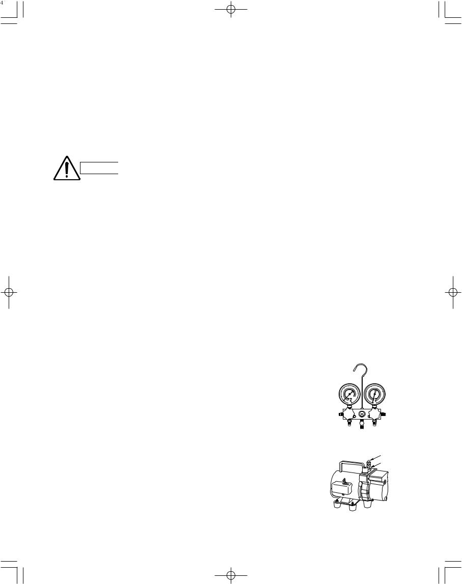
3. Different tools required
3-1.Tool specifications have been changed due to the characteristics of R410A. Some tools for R22and R407C-type refrigerant systems cannot be used.
|
New |
R407C tools |
|
|
Item |
compatible |
Remarks |
||
tool? |
||||
|
with R410A? |
|
||
|
|
|
|
|
Manifold gauge |
Yes |
No |
Types of refrigerant, refrigerating machine oil, and |
|
|
|
|
pressure gauge are different. |
|
|
|
|
|
|
Charge hose |
Yes |
No |
To resist higher pressure, material must be changed. |
|
|
|
|
|
|
Vacuum pump |
Yes |
Yes |
Use a conventional vacuum pump if it is equipped |
|
|
|
|
with a check valve. If it has no check valve, |
|
|
|
|
purchase and attach a vacuum pump adapter. |
|
|
|
|
|
|
Leak detector |
Yes |
No |
Leak detectors for CFC and HCFC that |
|
|
|
|
react to chlorine do not function because |
|
|
|
|
R410A contains no chlorine. Leak detector |
|
|
|
|
for HFC134a can be used for R410A. |
|
|
|
|
|
|
Flaring oil |
Yes |
No |
For systems that use R22, apply mineral oil (Suniso oil) |
|
|
|
|
to the flare nuts on the tubing to prevent refrigerant |
|
|
|
|
leakage. For machines that use R407C or R410A, apply |
|
|
|
|
synthetic oil (ether oil) to the flare nuts. |
|
|
|
|
|
Manifold gauge
Vacuum pump
Outlet
Inlet
* Using tools for R22 and R407C and new tools for R410A together can cause defects.
4
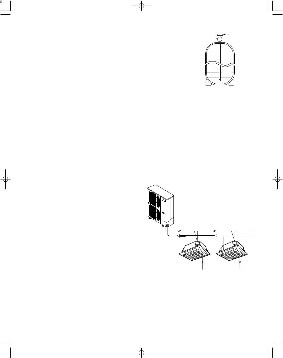
3-2. Use R410A exclusive cylinder only. |
Valve |
|
Single-outlet valve
(with siphon tube)
Liquid refrigerant should be recharged with the cylinder standing on end as shown.
 Liquid
New refrigerant R410A cannot be used for earlier models
1. Compressor specifications are different.
If recharging a R22 or R407C compressor with R410A, durability will significantly decrease since some of the materials used for compressor parts are different.
2. Existing tubing cannot be used (especially R22).
Completely cleaning out residual refrigerating
machine oil is impossible, even by flushing.
3. Refrigerating machine oil differs (R22).
Since R22 refrigerating machine oil is mineral oil, it does not dissolve in R410A.Therefore, refrigerating machine oil discharged from the compressor can cause compressor damage.
R22 refrigerating machine oil |
Mineral oil (Suniso oil) |
|
|
|
|
|
|
|
|
|
|
|
|
|
|
|
|
|
|
R407C refrigerating machine oil |
Synthetic fluid (ether oil) |
|
|
|
|
|
|
|
|
|
|
|
|
|
|
|
|
|
|
R410A refrigerating machine oil |
Synthetic fluid (ether oil) |
|
|
|
|
|
|
|
|
|
|
|
|
|
|
|
|
|
|
|
|
|
|
|
|
|
|
|
|
|
|
|
|
|
|
|
|
|
|
5
CONTENTS
Page
IMPORTANT . . . . . . . . . . . . . . . . . . . . . . . . . . . . . . 2
Please Read Before Starting
Check of Density Limit
Precautions for Installation Using New Refrigerant
1.GENERAL . . . . . . . . . . . . . . . . . . . . . . . . . . . . . 7
1-1. Tools Required for Installation (not supplied)
1-2. Accessories Supplied
1-3. Type of Copper Tube and Insulation Material 1-4. Additional Materials Required for Installation 1-5. Tubing Size
1-6. Straight Equivalent Length of Joints
1-7. Additional Refrigerant Charge
1-8. System Limitations
1-9. Tubing Length
1-10. Check of Limit Density
1-11. Installing Distribution Joint
1-12. Optional Distribution Joint Kit
1-13. Example of Tubing Size Selection and Refrigerant Charge Amount
2.SELECTING THE INSTALLATION SITE . . . . . 14
2-1. Outdoor Unit
2-2. Air-Discharge Chamber for Top Discharge 2-3. Installing the Unit in Heavy Snow Areas 2-4. Precautions for Installation in Heavy Snow
Areas
2-5. Dimensions of Air-Discharge Chamber
2-6. Dimensions of Outdoor Unit with Air-Discharge Chamber (field supply)
2-7. Dimensions of Snow Ducting
2-8. Dimensions of Outdoor Unit with Snow-Proof Ducting (field supply)
3. HOW TO INSTALL THE OUTDOOR UNIT . . . 21
3-1. Installing the Outdoor Unit
3-2. Drainage Work
3-3. Routing the Tubing and Wiring
|
|
Page |
4. |
ELECTRICAL WIRING . . . . . . . . . . . . . . . . . . 22 |
|
|
4-1. General Precautions on Wiring |
|
|
4-2. Recommended Wire Length and Wire |
|
|
|
Diameter for Power Supply System |
|
4-3. Wiring System Diagram |
|
5. |
HOW TO PROCESS TUBING . . . . . . . . . . . . . 26 |
|
|
5-1. Connecting the Refrigerant Tubing |
|
|
5-2. |
Connecting Tubing Between Indoor and |
|
|
Outdoor Units |
|
5-3. |
Insulating the Refrigerant Tubing |
|
5-4. |
Taping the Tubes |
|
5-5. |
Finishing the Installation |
6. AIR PURGING . . . . . . . . . . . . . . . . . . . . . . . . . 30
■Air Purging with a Vacuum Pump (for Test Run) Preparation
7. TEST RUN . . . . . . . . . . . . . . . . . . . . . . . . . . . . 33
7-1. Preparing for Test Run
7-2. Test Run Procedure
7-3. Outdoor Unit PCB Setting
7-4. Auto Address Setting
7-5. Caution for Pump Down
7-6. Meaning of Alarm Messages
6
1. GENERAL
This booklet briefly outlines where and how to install the air conditioning system. Please read over the entire set of instructions for the outdoor unit and make sure all accessory parts listed are with the system before beginning.
1-1. Tools Required for Installation (not supplied)
1.Flathead screwdriver
2.Phillips head screwdriver
3.Knife or wire stripper
4.Tape measure
5.Level gauge
6.Sabre saw or key hole saw
7.Hacksaw
8.Core bits
9.Hammer
10.Drill
11.Tube cutter
12.Tube flaring tool
13.Torque wrench
14.Adjustable wrench
15.Reamer (for deburring)
1-2. Accessories Supplied
See Table 1-1.
Table 1-1 (Outdoor Unit)
1-3. Type of Copper Tube and Insulation Material
If you wish to purchase these materials separately from a local source, you will need:
1.Deoxidized annealed copper tube for refrigerant tubing.
2.Foamed polyethylene insulation for copper tubes as required to precise length of tubing.Wall thickness of the insulation should be not less than 5/16".
3.Use insulated copper wire for field wiring. Wire size varies with the total length of wiring.
Refer to 4. ELECTRICAL WIRING for details.
CAUTION |
Check local electrical codes |
|
and regulations before |
||
|
||
|
||
|
obtaining wire. Also, check |
|
|
any specified instructions or |
|
|
limitations. |
1-4. Additional Materials Required for Installation
1.Refrigeration (armored) tape
2.Insulated staples or clamps for connecting wire (See your local codes.)
3.Putty
4.Refrigeration tubing lubricant
5.Clamps or saddles to secure refrigerant tubing
6.Scale for weighing
|
|
Q’ty |
||
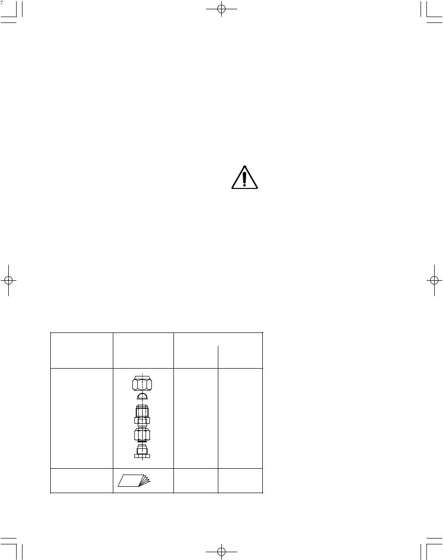
Part name |
Figure |
|
|
|
U-36LE1U6 |
U-52LE1U6 |
|||
|
|
|||
|
|
U-36LE1U6E |
U-52LE1U6E |
|
|
|
(4 hp) |
(6 hp) |
|
Tube Discharge |
0 |
1 |
|
Assy |
|||
|
|
Instruction manual |
paper |
1 |
1 |
hp = horsepower
7
1-5. Tubing Size
Table 1-2 Main Tubing Size (LA)
BTU/h (kW) |
38,200 (11.2) |
52,900 (15.5) |
|
System horsepower |
4 |
6 |
|
Gas tubing |
ø5/8" (ø15.88) |
ø3/4" (ø19.05) |
|
Liquid tubing |
ø3/8" (ø9.52) |
Unit: in. (mm) |
|
|
|
|
|
Note: If the system consists of only one indoor unit with an outdoor 6HP (Type 52), the main tube of the unit (LA) should be ø19.05. Convert ø19.05 to ø15.88 using a reducer (field supply) close to the indoor unit and then make the connection.
Table 1-3 Main Tubing Size After Distribution (LB, LC...)
Total capacity |
Below BTU/h |
24,200 (2.5 hp) |
38,200 (4 hp) 47,800 (5 hp) |
52,900 (6 hp) |
after distribution |
Over BTU/h |
– |
24,200 (2.5 hp) |
|
|
|
|||
Tubing size |
Gas tubing |
ø1/2" (ø12.7) |
ø5/8" (ø15.88) |
ø3/4" (ø19.05) |
Liquid tubing |
ø3/8" (ø9.52) |
ø3/8" (ø9.52) |
Unit: in. (mm) |
|
|
hp = horsepower |
|||
|
|
|
|
Note: In case the total capacity of connected indoor units exceeds the total capacity of the outdoor units, select the main tubing size for the total capacity of the outdoor units.
Table 1-4 Indoor Unit Tubing Connection ( |
1, |
2... n–1) |
|
|
|
|
|
|
|||||
Indoor unit type |
7 |
9 |
12 |
|
15 |
|
18 |
19 |
24 |
36 |
48 |
54 |
|
|
|
|
|
|
|
|
|
|
|
|
|
|
|
Gas tubing |
|
|
o1/2" (o12.7) |
|
|
|
|
o5/8" (o15.88) |
|
|
|||
|
|
|
|
|
|
|
|
|
|
|
|
||
Liquid tubing |
|
|
o1/4" (o6.35) |
|
|
|
|
o3/8" (o9.52) |
|
Unit: in. (mm) |
|||
1-6. Straight Equivalent Length of Joints
Design the tubing system by referring to the following table for the straight equivalent length of joints.
Table 1-5 Straight Equivalent Length of Joints |
|
|
Unit: ft. |
|
|
|
||||||||||
Gas tubing size (in. (mm)) |
|
|
|
|
1/2" (12.7) |
5/8" (15.88) |
3/4" (19.05) |
|
|
|
||||||
|
|
|
|
|
|
|
|
|
|
|
|
|
|
|
|
|
90° elbow |
|
|
|
|
|
1 |
|
1.1 |
1.4 |
|
|
|
|
|||
|
|
|
|
|
|
|
|
|
||||||||
|
|
|
|
|
|
|
|
|
||||||||
|
|
|
|
|
|
|
|
|
|
|
|
|
|
|
|
|
45° elbow |
|
|
|
|
|
0.8 |
|
0.9 |
1 |
|
|
|
|
|||
|
|
|
|
|
|
|
|
|
|
|
|
|
|
|
|
|
U-shape tube bend (R2-3/8" – 4" (60 – 100)) |
|
3 |
|
3.4 |
4.1 |
|
|
|
|
|||||||
|
|
|
|
|
|
|
|
|
|
|
|
|
|
|
|
|
Trap bend |
|
|
|
|
|
7.5 |
|
9.2 |
10.5 |
|
|
|
|
|||
|
|
|
|
|
|
|
|
|
|
|
|
|
|
|
||
Y-branch distribution joint |
|
|
|
|
Equivalent length conversion not needed. |
|
|
|
||||||||
|
|
|
|
|
|
|
|
|
|
|
|
|
||||
Ball valve for service |
|
|
|
|
Equivalent length conversion not needed. |
|
|
|
||||||||
|
|
|
|
|
|
|
|
|
|
|
|
|
|
|
|
|
Table 1-6 Required Copper Tubing Dimensions |
|
|
|
|
|
|
Unit: in. (mm) |
|||||||||
|
|
|
|
|
|
|
|
|
|
|
|
|
|
|
|
|
Material |
|
|
|
|
|
|
|
|
|
|
O |
|
|
|
||
|
|
|
|
|
|
|
|
|
|
|||||||
Copper tube |
Outer diameter |
1/4 (6.35) |
|
3/8 (9.52) |
|
1/2 (12.7) |
|
5/8 (15.88) |
3/4 (19.05) |
|||||||
|
|
|
|
|
|
|
|
|
|
|
|
|
|
|
|
|
Wall thickness |
1/32 (0.8) |
|
1/32 (0.8) |
|
1/32 (0.8) |
|
5/128 (1.0) |
over 5/128 (1.0) |
||||||||
|
|
|
|
|||||||||||||
|
|
|
|
|
|
|
|
|
|
|
|
|
|
|
|
|
1-7. Additional Refrigerant Charge
Additional refrigerant charge amount is calculated from the liquid tubing total length as follows.
Table 1-7 Amount of Refrigerant Charge Per ft., According to Liquid Tubing Size
Liquid tubing size |
Amount of refrigerant |
(in. (mm)) |
charge (oz/ft.) |
ø1/4" (ø6.35) |
0.279 |
ø3/8" (ø9.52) |
0.602 |
Required amount of charge = (Amount of refrigerant charge per ft. of each size of liquid tube × its tube length) + (...) + (...)
*Always charge accurately using a scale for weighing.
8

Table 1-8 Refrigerant Charge Amount at Shipment (for outdoor unit)
Heat pump unit |
U-36LE1U6 |
U-52LE1U6 |
|
U-36LE1U6E |
U-52LE1U6E |
||
(Single-phase) |
|||
|
|
||
(oz) |
123 |
123 |
|
|
|||
|
|
|
1-8. System Limitations
Table 1-9 System Limitations
Outdoor units |
U-36LE1U6 |
U-52LE1U6 |
|
U-36LE1U6E |
U-52LE1U6E |
||
|
|||
|
|
|
|
Number of max. connectable indoor units |
6 |
9 |
|
|
|
|
|
Max. allowable indoor/outdoor capacity ratio |
50 – 130% |
||
|
|
|
|
1-9. Tubing Length
Select the installation location so that the length and size of refrigerant tubing are within the allowable range shown in the figure below.
LA |
|
|
|
|
|
L1 |
|
|
|
|
|
|
|
|
|
|
L2 |
|
|
|
|
||
|
|
|
|
|
|
|
|
|
|
||
Main tube of unit |
|
LB |
|
LC |
|
LD |
|
n |
|
|
|
|
|
|
|
|
|
|
|
|
|
|
|
1st branch |
|
|
|
|
|
|
|
|
|
|
|
|
|
|
|
|
|
|
|
|
|
|
|
|
|
|
|
|
|
|
|
|
|
|
|
|
|
|
|
|
|
|
|
|
|
|
|
|
L3 1 |
2 |
|
3 |
|
n-1 |
|
|
|||
Unit distribution tube |
|
|
|
|
|
|
|
|
|
|
|
|
|
|
|
|
|
|
|
|
|
|
|
|
|
|
|
|
|
|
|
|
|
|
|
H1
H2
Note: Do not use commercially available T-joints for the liquid tubing. |
|
|
R410A distribution joint |
|
|
* Be sure to use special R410A distribution joints (CZ: purchased separately) for outdoor |
|
unit connections and tubing branches. |
CZ-P160BK1U (for indoor unit) |
Table 1-10 Ranges that Apply to Refrigerant Tubing Lengths and to Differences in Installation Heights
Items |
Marks |
|
Contents |
|||
|
L1 |
|
Max. tubing length |
|
Actual length |
|
|
|
|
||||
|
|
|
Equivalent length |
|||
|
|
|
|
|
||
Allowable tubing |
L (L2 – L3) |
Difference between max. length and min. |
||||
length from the No.1 distribution joint |
||||||
length |
|
|
||||
|
|
|
|
|
||
|
LA |
|
Max. length of main tubing (at max. diameter) |
|||
|
1, 2... n |
|
Max. length of each distribution tube |
|||
|
1+ 2 +... n–1 |
+L1 |
Total max. tubing length including length of |
|||
|
each distribution tube (only narrow tubing) |
|||||
|
|
|
||||
|
H1 |
|
When outdoor unit is installed higher than indoor unit |
|||
Allowable elevation |
|
When outdoor unit is installed lower than indoor unit |
||||
difference |
|
|
||||
H2 |
|
Max. difference between indoor units |
||||
|
|
|||||
|
|
|
|
|
|
|
L = Length, H = Height
Length (ft.)
> |
|
|
492 |
> |
574 |
|
|
> |
131 |
|
|
> |
262 |
|
|
> |
98 |
|
|
> |
656 |
|
|
> |
164 |
|
|
> |
131 |
|
|
> |
49 |
|
|
9
Always check the gas density WARNING limit for the room in which the
unit is installed.
1-10. Check of Limit Density
When installing an air conditioner in a room, it is necessary to ensure that even if the refrigerant gas accidentally leaks out, its density does not exceed the limit level for that room.
CAUTION |
Pay special attention to any |
|
location, such as a basement, |
|
|
|
etc., where leaking refrigerant |
|
can accumulate, since refrig- |
|
erant gas is heavier than air. |
1-11. Installing Distribution Joint
(1)Refer to “HOW TO ATTACH DISTRIBUTION JOINT” enclosed with the optional distribution joint kit (CZ-P160BK1U).
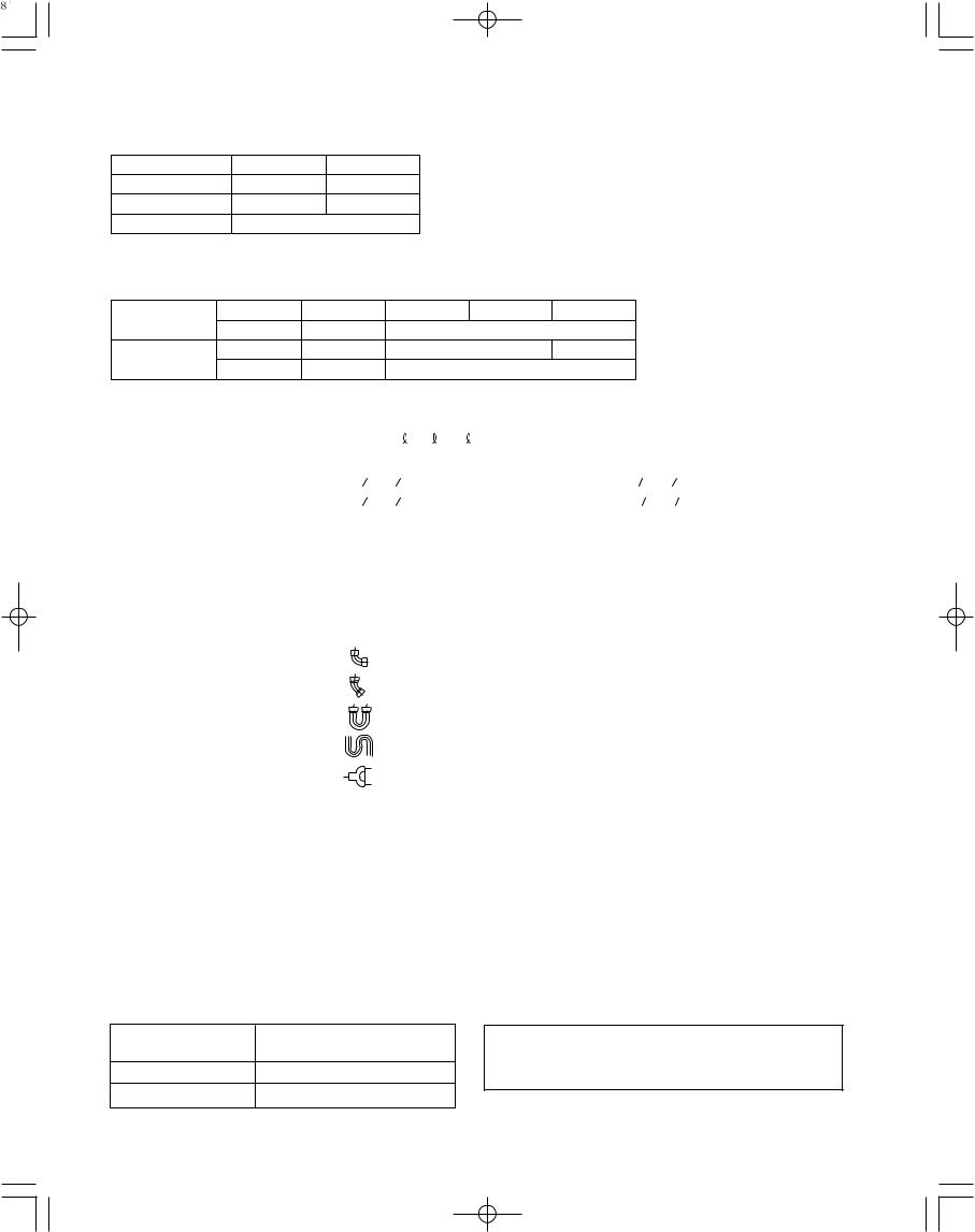
(2)In order to prevent accumulation of refrigerant oil in stopped units, if the main tubing is horizontal then each branch tubing length should be at an angle that is greater than horizontal. If the main tubing is vertical, provide a raised starting portion for each branch.
(3)If there are height differences between indoor units or if branch tubing that follows a distribution joint is connected to only 1 unit, a trap or ball valve must be added to that distribution joint. (When adding the ball valve, locate it within 1.3 ft. of the distribution joint.)
If a trap or ball valve is not added, do not operate the system before repairs to a malfunctioning unit are completed. (The refrigerant oil sent through the tubing to the malfunctioning unit will accumulate and may damage the compressor.)
Tube branching methods (horizontal use)
|
|
|
to |
30° |
|
|
15 |
|
|
|
|
|
|
|
|
|
|
|
B |
|
A |
Horizontal A |
||
B |
line |
|
View as seen |
|
|
|
|
||
|
|
|
|
from arrow |
|
|
Arrow view |
|
|
Types of vertical trap specifications
(When using ball valve)
Main tubing
Ball valve |
Indoor unit (more than 2 units) |
||
(If only 1 unit is connected, |
|||
(BV: purchased |
|||
a ball valve is also needed on this side.) |
|||
separately) |
|||
|
|
||
Indoor unit (1) |
|
||
(When not using ball valve) |
|||
Main tubing |
Horizontal |
|
|
|
(Each unit is connected to |
||
|
Indoor unit |
||
|
|
tubing that is either level |
|
|
Branch tubing is |
or is directed downward.) |
|
|
directed upward. |
|
|
More than 8 in.
Indoor unit is directed downward
10
1-12. Optional Distribution Joint Kit
See the installation instructions packaged with the distribution joint kit for the installation procedure.
Table 1-11
Model name |
Cooling capacity after distribution |
Remarks |
|
|
|
CZ-P160BK1U |
76,400 BTU/h (22.4 kW) or less |
For indoor unit |
|
|
|
CZ-P160BK1U
Use: For indoor unit (Capacity after distribution joint is 76,400 BTU/h (22.4 kW) or less.)
Example
Gas tube |
Liquid tube |
|
|
4-21/64 |
|
|
|
|
3-13/16 |
|
|
|
|
B |
C |
|
A |
B |
A |
||
B |
||||
Distribution |
|
|||
|
|
|||
Joint |
|
|
|
|
|
|
C |
|
|
53/64-2
|
|
4-21/64 |
|
|
|
3-13/16 |
|
D |
C |
C |
DE |
C
Distribution
Joint
D
E
53/64-2
Insulation
Insulation |
Unit: in. |
Table 1-12 Size of connection point on each part (Shown are inside diameters of tubing)
Size |
Part A |
Part B |
Part C |
Part D |
Part E |
|
|
|
|
|
|
|
|
in. (mm) |
ø3/4" |
ø5/8" |
ø1/2" |
ø3/8" |
ø1/4" |
|
(ø19.05) |
(ø15.88) |
(ø12.7) |
(ø9.52) |
(ø6.35) |
||
|
||||||
|
|
|
|
|
|
11
1-13. Example of Tubing Size Selection and Refrigerant Charge Amount
Additional refrigerant charging
Based on the values in Tables 1-2, 1-3, 1-4 and 1-7, use the liquid tubing size and length, and calculate the amount of additional refrigerant charge using the formula below.
Required additional
refrigerant charge (oz) = 0.602 × (a) + 0.279 × (b)
(a): Liquid tubing |
Total length of ø3/8" (ft.) |
(b): Liquid tubing |
Total length of ø1/4" (ft.) |
●Charging procedure
Be sure to charge with R410A refrigerant in liquid form.
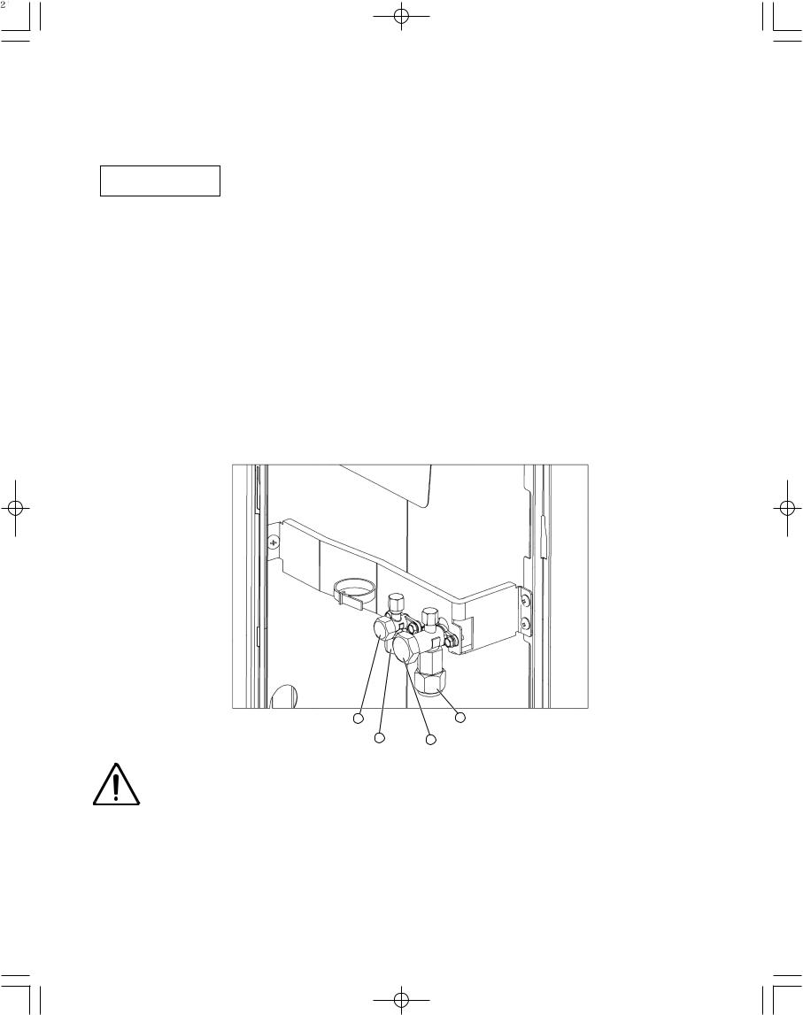
1.After performing a vacuum, charge with refrigerant from the liquid tubing side. At this time, all valves must be in the “fully closed” position.
2.If it was not possible to charge the designated amount, operate the system in Cooling mode while charging with refrigerant from the gas tubing side. (This is performed at the time of the test run. For this, all valves must be in the “fully open” position.)
Charge with R410A refrigerant in liquid form.
With R410A refrigerant, charge while adjusting the amount being fed a little at a time in order to prevent liquid refrigerant from backing up.
●After charging is completed, turn all valves to the “fully open” position.
●Replace the tubing covers as they were before.
Tightening torque for valve stem cap: 160 – 180 lbs · in. 4 |
1 Tightening torque: 590 – 710 lbs · in. |
Tightening torque: 300 – 360 lbs · in. 3 |
2 Tightening torque for valve stem cap: 240 – 280 lbs · in. |
CAUTION |
1. |
R410A additional charging absolutely must be done through liquid charging. |
|
2. |
The R410A refrigerant cylinder has a gray base color, and the top part is pink. |
|
||
|
3. |
The R410A refrigerant cylinder includes a siphon tube. Check that the siphon |
|
|
tube is present. (This is indicated on the label at the top of the cylinder.) |
|
4. |
Due to differences in the refrigerant, pressure, and refrigerant oil involved in |
|
|
installation, it is not possible in some cases to use the same tools for R22 and |
|
|
for R410A. |
12
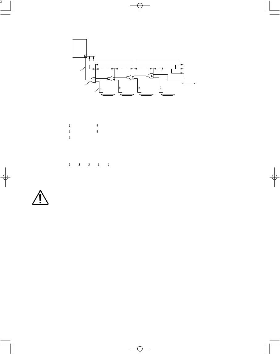
Example:
|
LA |
|
|
|
|
|
L1 |
|
|
|
|
|
||
|
|
|
|
|
|
L2 |
|
|
|
|
|
|||
|
|
|
|
|
|
|
|
|
|
|
|
|||
Main tube of unit |
|
LB |
|
LC |
|
LN |
|
n |
||||||
|
|
|
|
|
|
|
|
|
|
|
|
|
||
|
1st branch |
|
|
|
|
|
|
|
|
|
|
|
|
|
|
|
|
|
|
|
|
|
|
|
|
|
|
|
|
|
1 |
|
|
2 |
|
3 |
|
|
|
|
18 type |
|||
|
|
|
|
|
|
|
|
|
||||||
Unit distribution tube |
|
|
|
|
|
n–1 |
||||||||
|
|
|
|
|
|
|
|
|
|
|
|
|
||
|
|
|
7 type |
|
9 type |
12 type |
18 type |
|||||||
● Example of each tubing length |
|
|
|
|
|
|
|
|
|
|
|
|
|
|
Main tubing |
Distribution joint tubing |
|
|
|
|
|
|
|
|
|
|
|||
LA = 131 ft. |
Indoor side |
|
|
|
|
|
|
|
|
|
|
|
|
|
LB = 16 ft. |
1 = 16 ft. |
4 = 20 ft. |
|
|
|
|
|
|
|
|
|
|
||
LC = 16 ft. |
2 = 16 ft. |
5 = 16 ft. |
|
|
|
|
|
|
|
|
|
|
||
LD = 49 ft. |
3 = 7 ft. |
|
|
|
|
|
|
|
|
|
|
|
|
|
●Obtain charge amount for each tubing size
Note that the charge amounts per 3.3 ft. are different for each liquid tubing size.
ø3/8" (ø9.52) → |
LA |
+ |
LB |
+ |
LC + LD |
: 212 ft. × 0.602 oz/ft. |
= |
127 oz |
ø1/4" (ø6.35) → |
1 |
+ |
2 |
+ |
3 + 4 + |
5 : 75 ft. × 0.279 oz/ft. |
= |
20 oz |
|
|
|
|
|
|
|
|
|
|
|
|
|
|
|
Total |
|
147 oz |
Additional refrigerant charge amount is 147 oz.
CAUTION |
Be sure to check the limit |
|
density for the room in which |
||
|
||
|
||
|
the indoor unit is installed. |
13
2. SELECTING THE INSTALLATION SITE
2-1. Outdoor Unit
AVOID:
●heat sources, exhaust fans, etc. (Fig. 2-1)
●damp, humid or uneven locations
DO:
●choose a place as cool as possible.
●choose a place that is well ventilated and outside air temperature does not exceed maximum 113°F constantly.
●allow enough room around the unit for air intake/ exhaust and possible maintenance. (Fig. 2-2)
●use lug bolts or equal to bolt down unit, reducing vibration and noise.
Installation space
Exhaust fan
Hot air
Heat source
Outdoor unit
Fig. 2-1
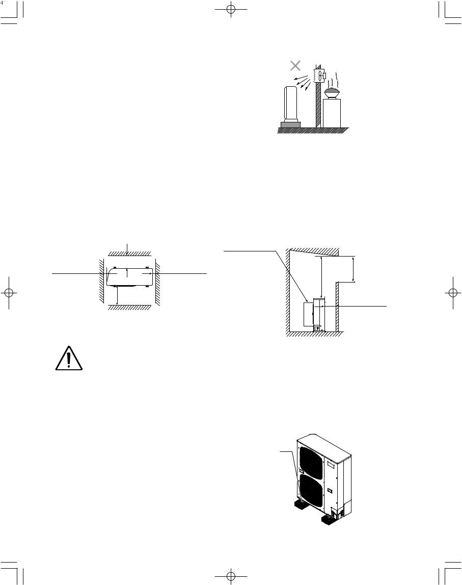
Distance between obstructions and the unit air inlet and outlet must be as shown below.
|
*3 |
|
Inlet side C |
More than 25/64" |
More than 25/64" |
*2 |
*4 |
Outlet side
More than
3.3ft.
*1
(Obstruction above unit)
Air direction chamber (field supply)
|
B |
|
A |
*1 |
Inlet side |
More than 8 in. |
|
|
(Obstruction on |
|
inlet side) |
Fig. 2-2
(Ground)
|
Fig. 2-3 |
|
|
● Concerning inlet-side distance “C” (Fig. 2-2) |
|
CAUTION |
||
The minimum for distance “C” is 6 in. if there are no obstructions on the outlet side |
||
|
||
|
(wall *1 side) and *2 or *4 is not present. In all other cases, the minimum for distance |
|
|
“C” is 8 in. |
|
|
● If the unit is installed with the outlet side facing wall *1, then there must be no obstruc- |
|
|
tions on 2 of the remaining 3 sides: *2, *3, *4. |
|
|
● If wall *1 is on the outlet side (Fig. 2-2), or if obstructions are present on all 3 sides *2, |
|
|
*3, and *4 (Fig. 2-2), then the minimum distance for “A” and “B” is 6.6 ft. (Fig. 2-4). |
|
|
Even if there is no wall on the outlet side, a minimum of 3.3 ft. is required. |
In case of multiple installations
●provide a solid base (concrete block, 4 × 16 in. beams or equal), a minimum of 6 in. above ground level to reduce humidity and protect the unit against possible water damage and decreased service life. (Fig. 2-4)
●use lug bolts or equal to bolt down unit, reducing vibration and noise.
Anchor bolts (4 pieces)
Fig. 2-4
14
2-2. Air Discharge Chamber for Top Discharge
Be sure to install an air discharge chamber (field supply) in the field when:
●it is difficult to keep a space of min. 20 in. between the air discharge outlet and an obstacle.
●the air discharge outlet is facing a sidewalk and discharged hot air may annoy passers-by. Refer to Fig. 2-5.
2-3. Installing the Unit in Heavy Snow Areas
In locations with strong wind, snow-proof ducting (field supply) should be fitted and direct exposure to the wind should be avoided as much as possible.
■ Countermeasures against snow and wind
In regions with snow and strong wind, the following problems may occur when the outdoor unit is not provided with a platform and snow-proof ducting:
a)The outdoor fan may not run and damage to the unit may occur.
b)There may be no air flow.
c)The tubing may freeze and burst.
d)The condenser pressure may drop because of strong wind, and the indoor unit may freeze.
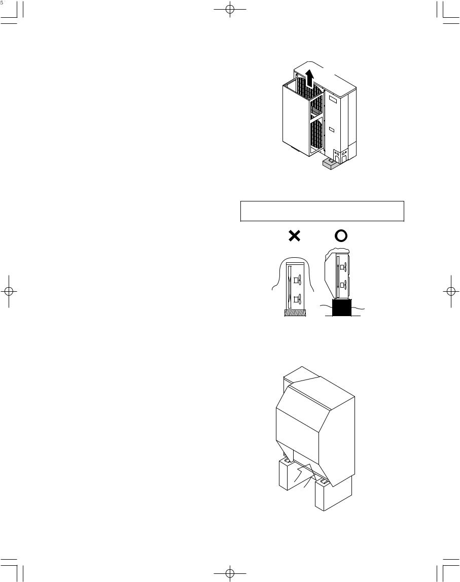
2-4. Precautions for Installation in Heavy Snow Areas
(1)The platform should be higher than the max. snow depth. (Fig. 2-6)
(2)The 2 anchoring feet of the outdoor unit should be used for the platform, and the platform should be installed beneath the air intake side of outdoor unit.
(3)The platform foundation must be firm and the unit must be secured with anchor bolts.
(4)In case of installation on a roof subject to strong wind, countermeasures must be taken to prevent the unit from being blown over.
Air discharge
Fig. 2-5
In regions with significant snowfall, the outdoor unit should be provided with a platform and snow-proof ducting.
Without snow- |
With snow- |
proof ducting |
proof ducting |
(Low platform) |
(High platform) |
Fig. 2-6
Outdoor
Unit
Duct
Air
Intake
Fig. 2-7
15
 Loading...