


SERVICE MANUAL
MINI VRF SYSTEM
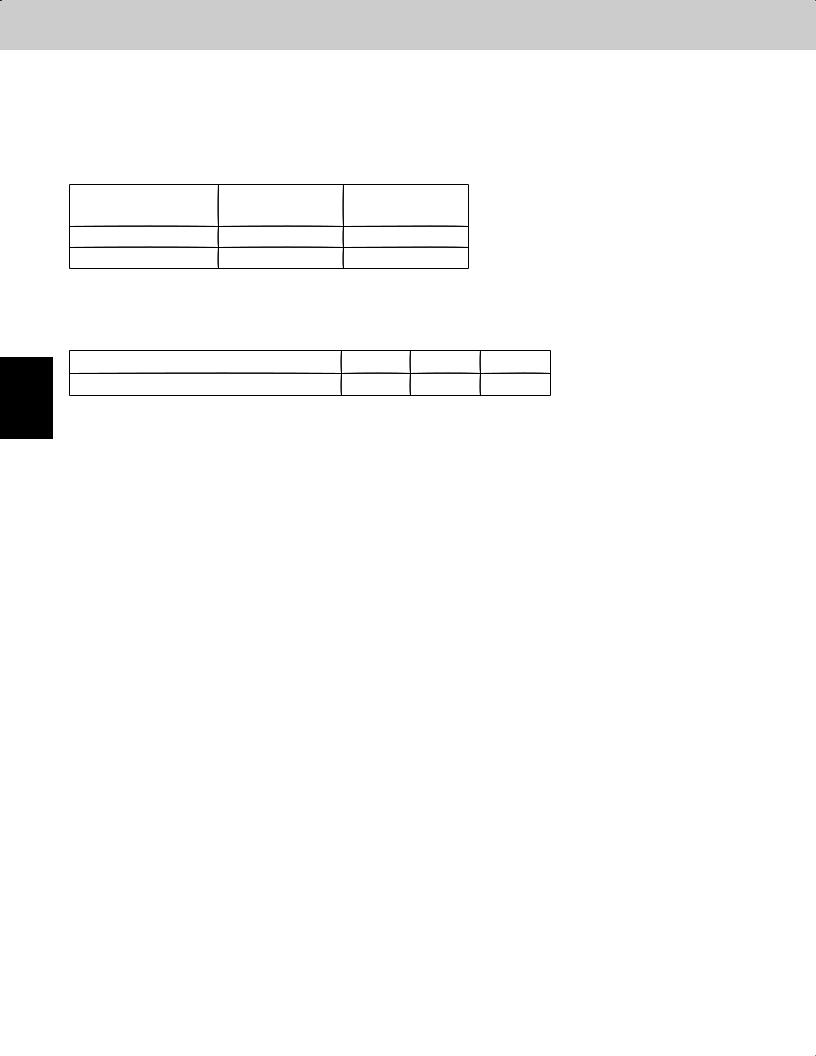
Model No.
Outdoor Units
Class |
36 |
52 |
|
Model Name |
U-36LE1U6 |
U-52LE1U6 |
|
U-36LE1U6E* |
U-52LE1U6E* |
||
|
Refrigerant R410A is used in the outdoor units. * Salt-Air Damage Resistant Specifications.
Indoor Units
|
Class |
7 |
9 |
12 |
15 |
18 |
19 |
24 |
36 |
48 |
54 |
|
|
|
|
|
|
|
|
|
|
|
|
U1 |
4-Way Cassette |
|
|
S-12MU1U6 |
|
S-18MU1U6 |
|
S-24MU1U6 |
S-36MU1U6 |
|
|
Y1 |
4-Way Cassette 60×60 |
|
|
S-12MY1U6 |
|
S-18MY1U6 |
|
|
|
|
|
D1 |
1-Way Cassette |
S-07MD1U6 |
S-09MD1U6 |
S-12MD1U6 |
|
|
|
|
|
|
|
F1 |
Low Silhouette Ducted |
S-07MF1U6 |
S-09MF1U6 |
S-12MF1U6 |
S-15MF1U6 |
S-18MF1U6 |
|
S-24MF1U6 |
S-36MF1U6 |
S-48MF1U6 |
S-54MF1U6 |
M1 |
Slim Low Static Ducted |
S-07MM1U6 |
S-09MM1U6 |
S-12MM1U6 |
S-15MM1U6 |
S-18MM1U6 |
|
|
|
|
|
E1 |
High Static Pressure |
|
|
|
|
|
|
|
S-36ME1U6 |
S-48ME1U6 |
|
Ducted |
|
|
|
|
|
|
|
|
|||
T1 |
Ceiling |
|
|
S-12MT1U6 |
|
S-18MT1U6 |
|
S-24MT1U6 |
|
|
|
K1 |
Wall Mounted |
S-07MK1U6 |
S-09MK1U6 |
S-12MK1U6 |
|
S-18MK1U6 |
S-19MS1U6** |
S-24MK1U6 |
|
|
|
P1 |
Floor Standing |
S-07MP1U6 |
S-09MP1U6 |
S-12MP1U6 |
S-15MP1U6 |
S-18MP1U6 |
|
S-24MP1U6 |
|
|
|
R1 |
Concealed Floor |
S-07MR1U6 |
S-09MR1U6 |
S-12MR1U6 |
S-15MR1U6 |
S-18MR1U6 |
|
S-24MR1U6 |
|
|
|
Standing |
|
|
|
|
|||||||
|
|
|
|
|
|
|
|
|
|
|
|
** Necessary to install the External Electronic Expansion Valve Kit (Optional:CZ-P56SVK1U).
85464849297000 |
REFERENCE NO. SM830197-00 |
IMPORTANT!
Please Read Before Starting
This air conditioning system meets strict safety and operating standards. As the installer or service person, it is an important part of your job to install or service the system so it operates safely and efficiently.
For safe installation and trouble-free operation, you must:
 Carefully read this instruction booklet before beginning.
 Follow each installation or repair step exactly as shown.
 Observe all local, state, and national electrical codes.
 Pay close attention to all warning and caution notices given in this manual.
This symbol refers to a hazard or
WARNING
unsafe practice which can result in severe personal injury or death.
This symbol refers to a hazard or
unsafe practice which can result CAUTION in personal injury or product or
property damage.
If Necessary, Get Help
These instructions are all you need for most installation sites and maintenance conditions. If you require help for a special problem, contact our sales/service outlet or your certified dealer for additional instructions.
In Case of Improper Installation
The manufacturer shall in no way be responsible for improper installation or maintenance service, including failure to follow the instructions in this document.
SPECIAL PRECAUTIONS
WARNING When Wiring
ELECTRICAL SHOCK CAN CAUSE
SEVERE PERSONAL INJURY OR DEATH.
ONLY A QUALIFIED, EXPERIENCED
ELECTRICIAN SHOULD ATTEMPT TO
WIRE THIS SYSTEM.
•Do not supply power to the unit until all wiring and tubing are completed or reconnected and checked.
•Highly dangerous electrical voltages are used in this system. Carefully refer to the wiring diagram and these instructions when wiring. Improper connections and inadequate grounding can cause accidental injury or death.
•Ground the unit following local electrical codes.
•Connect all wiring tightly. Loose wiring may cause overheating at connection points and a possible fire hazard.
•To prevent possible hazards from insulation failure,
the unit must be grounded.
When Installing…
Select an installation location which is rigid and strong enough to support or hold the unit, and select a location for easy maintenance.
…In a Room
Properly insulate any tubing run inside a room to prevent “sweating” that can cause dripping and water damage to walls and floors.
Keep the fire alarm and the air outlet at CAUTION least 5 feet away from the unit.
…In Moist or Uneven Locations
Use a raised concrete pad or concrete blocks to provide a solid, level foundation for the outdoor unit. This prevents water damage and abnormal vibration.
…In an Area with High Winds
Securely anchor the outdoor unit down with bolts and a metal frame. Provide a suitable air baffle.
…In a Snowy Area (for Heat Pump-type Systems)
Install the outdoor unit on a raised platform that is higher than drifting snow. Provide snow vents.
When Connecting Refrigerant Tubing
•Ventilate the room well, in the event that is refrigerant gas leaks during the installation. Be careful not to allow contact of the refrigerant gas with a flame as this will cause the generation of poisonous gas.
•Keep all tubing runs as short as possible.
•Use the flare method for connecting tubing.
•Apply refrigerant lubricant to the matching surfaces of the flare and union tubes before connecting them, then tighten the nut with a torque wrench for a leak-free connection.
•Check carefully for leaks before starting the test run.
•When performing piping work do not mix air except for specified refrigerant (R410A) in refrigeration cycle. It causes capacity down, and risk of explosion and injury due to high
WARNING |
tension inside the refrigerant |
|
cycle. |
|
• Refrigerant gas leakage may |
|
cause fire. |
|
• Do not add or replace refrigerant |
|
other than specified type. |
|
It may cause product damage, |
|
burst and injury etc. |
When Transporting
Be careful when picking up and moving the indoor and outdoor units. Get a partner to help, and bend your knees when lifting to reduce strain on your back. Sharp edges or thin aluminum fins on the air conditioner can cut your fingers.
•Do not leak refrigerant while piping work for an installation or re-installation, and while repairing refrigeration parts.
Handle liquid refrigerant carefully as it may cause frostbite.
i
When Servicing
•Turn the power OFF at the main power box (mains) before opening the unit to check or repair electrical parts and wiring.
•Keep your fingers and clothing away from any moving parts.
•Clean up the site after you finish, remembering to check that no metal scraps or bits of wiring have been left inside the unit being serviced.
|
• |
Do not clean inside the indoor and |
WARNING |
||
|
|
outdoor units by users. Engage |
|
|
authorized dealer or specialist for |
|
|
cleaning. |
|
• |
In case of malfunction of this |
|
|
appliance, do not repair by yourself. |
|
|
Contact to the sales dealer or service |
|
|
dealer for a repair. |
CAUTION
Others
• Do not touch the air inlet or the sharp aluminum fins of the  outdoor unit. You may get injured.
•Ventilate any enclosed areas when installing or testing the refrigeration system. Escaped refrigerant gas, on contact with fire or heat, can produce dangerously toxic gas.
•Confirm after installation that no refrigerant gas is leaking. If the gas comes in contact with a burning stove, gas water heater, electric room heater or other heat source, it can cause the generation of poisonous gas.
|
• Do not touch the air inlet or the |
|
CAUTION |
||
sharp aluminum fins of the |
||
|
||
|
outdoor unit. You may get injured. |
• Do not sit or step on the unit, you may fall down accidentally.
• Do not stick any object into the FAN CASE.
You may be injured and the unit may be damaged.
Check of Density Limit
The room in which the air conditioner is to be installed requires a design that in the event of refrigerant gas leaking out, its density will not exceed a set limit.
The refrigerant (R410A), which is used in the air conditioner, is safe, without the toxicity or combustibility of ammonia, and is not restricted by laws imposed to protect the ozone layer. However, since it contains more than air, it poses the risk of suffocation if its density should rise excessively. Suffocation from leakage of refrigerant is almost non-existent. With the recent increase in the number of high density buildings, however, the installation of multi air conditioner systems is on the increase because of the need for effective use of floor space, individual control, energy conservation by curtailing heat and carrying power, etc.
Most importantly, the multi air conditioner system is able to replenish a large amount of refrigerant compared to conventional individual air conditioners. If a single unit of the multi air conditioner system is to be installed in a small room, select a suitable model and installation procedure so that if the refrigerant accidentally leaks out, its density does not reach the limit (and in the event of an emergency, measures can be made before injury can occur).
ASHRAE and the International Mechanical Code of the ICC as well as CSA provide guidance and define safeguards related to the use of refrigerants, all of which define a Refrigerant Concentration Level (RCL) of 25 pounds
per 1,000 cubic feet for R410A refrigerant.
For additional guidance and precautions related to refrigerant safety, please refer to the following documents:
International Mechanical Code 2009 (IMC-2009) (or more recently revised)
ASHRAE 15
ASHRAE 34
ii
Precautions for Installation Using New Refrigerant
1.Care regarding tubing
1-1.Process tubing
 Material:Use C1220 phosphorous deoxidized copper specified in JIS H3300 “Copper and Copper Alloy Seamless Pipes and Tubes.”
 Tubing size:Be sure to use the sizes indicated in the table below.
 Use a tube cutter when cutting the tubing, and be sure to remove any flash.This also applies to distribution joints (optional).
 When bending tubing, use a bending radius that is 4 times the outer diameter of the tubing or larger.
Use sufficient care in handling the tubing.Seal the tubing ends with CAUTION caps or tape to prevent dirt,moisture,or other foreign substances
from entering.These substances can result in system malfunction.
|
|
|
|
|
|
|
Unit: in. (mm) |
|
|
|
|
|
|
|
|
|
|
Material |
|
|
O |
|
|
|
|
|
Copper tube |
Outer diameter |
1/4 (6.35) |
3/8 (9.52) |
1/2 (12.7) |
5/8 (15.88) |
3/4 (19.05) |
|
|
|
|
|
|
|
|
|
|
|
Wall thickness |
1/32 (0.8) |
1/32 (0.8) |
1/32 (0.8) |
5/128 (1.0) |
5/128 (1.0) |
|
||
|
|
|||||||
|
|
|
|
|
|
|
|
|
1-2. Prevent impurities including water, dust and oxide from entering the tubing. Impurities can cause R410A refrigerant deterioration and compressor defects. Due to the features of the refrigerant and refrigerating machine oil, the prevention of water and other impurities becomes more important than ever.
2. Be sure to recharge the refrigerant only in liquid form.
2-1. Since R410A is a non-azeotrope, recharging the refrigerant in gas form can lower performance and cause defects of the unit.
2-2. Since refrigerant composition changes and performance decreases when gas leaks, collect the remaining refrigerant and recharge the required total amount of new refrigerant after fixing the leak.
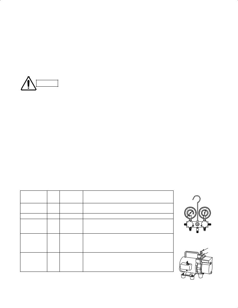
3. Different tools required
3-1.Tool specifications have been changed due to the characteristics of R410A. Some tools for R22and R407C-type refrigerant systems cannot be used.
|
New |
R407C tools |
|
Manifold gauge |
|
|
|
|
|||
Item |
compatible |
Remarks |
|
||
tool? |
|
||||
|
with R410A? |
|
|
||
Manifold gauge |
Yes |
No |
Types of refrigerant, refrigerating machine oil, and |
|
|
|
|
|
pressure gauge are different. |
|
|
Charge hose |
Yes |
No |
To resist higher pressure, material must be changed. |
|
|
Vacuum pump |
Yes |
Yes |
Use a conventional vacuum pump if it is equipped |
|
|
|
|
|
with a check valve. If it has no check valve, |
|
|
|
|
|
purchase and attach a vacuum pump adapter. |
|
|
Leak detector |
Yes |
No |
Leak detectors for CFC and HCFC that |
|
|
|
|
|
react to chlorine do not function because |
Vacuum pump |
|
|
|
|
R410A contains no chlorine. Leak detector |
Outlet |
|
|
|
|
for HFC134a can be used for R410A. |
||
|
|
|
Inlet |
||
Flaring oil |
Yes |
No |
For systems that use R22, apply mineral oil (Suniso oil) |
||
|
|||||
|
|
|
to the flare nuts on the tubing to prevent refrigerant |
|
|
|
|
|
leakage. For machines that use R407C or R410A, apply |
|
|
|
|
|
synthetic oil (ether oil) to the flare nuts. |
|
* Using tools for R22 and R407C and new tools for R410A together can cause defects.
iii
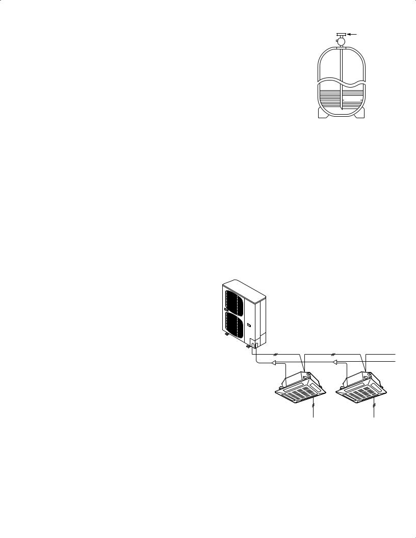
3-2.Use R410A exclusive cylinder only. |
Valve |
|
Single-outlet valve
(with siphon tube)
Liquid refrigerant should be recharged with the cylinder standing on end as shown.
 Liquid
New refrigerant R410A cannot be used for earlier models
1.Compressor specifications are different.
If recharging a R22 or R407C compressor with R410A, durability will significantly decrease since some of the materials used for compressor parts are different.
2.Existing tubing cannot be used (especially R22).
Completely cleaning out residual refrigerating
machine oil is impossible, even by flushing.
3.Refrigerating machine oil differs (R22).
Since R22 refrigerating machine oil is mineral oil, it does not dissolve in R410A.Therefore, refrigerating machine oil discharged from the compressor can cause compressor damage.
R22 refrigerating machine oil |
Mineral oil (Suniso oil) |
|
|
|
|
|
|
|
|
|
|
|
|
|
|
|
|
|
|
R407C refrigerating machine oil |
Synthetic fluid (ether oil) |
|
|
|
|
|
|
|
|
|
|
|
|
|
|
|
|
|
|
R410A refrigerating machine oil |
Synthetic fluid (ether oil) |
|
|
|
|
|
|
|
|
|
|
|
|
|
|
|
|
|
|
|
|
|
|
|
|
|
|
|
|
|
|
|
|
|
|
|
|
|
|
iv

CONTENTS
Section 1: CONTROL FUNCTIONS. . . . . . . . . . . . . . . . . . . . . . . . . . . . . . . . . . . . . . . . . . 1-1
1. Introduction . . . . . . . . . . . . . . . . . . . . . . . . . . . . . . . . . . . . . . . . . . . . . . . . . 1-2
2. Compressor Control . . . . . . . . . . . . . . . . . . . . . . . . . . . . . . . . . . . . . . . . . . 1-3
3. Special Controls . . . . . . . . . . . . . . . . . . . . . . . . . . . . . . . . . . . . . . . . . . . . . 1-7
4. Other Control. . . . . . . . . . . . . . . . . . . . . . . . . . . . . . . . . . . . . . . . . . . . . . . 1-10
5. Operation of Solenoid Valves . . . . . . . . . . . . . . . . . . . . . . . . . . . . . . . . . . 1-10
6. Outdoor Unit Electronic Control Valve (Motor Valve) Control [MOV1] . . . . 1-10
7. Outdoor Fan Control . . . . . . . . . . . . . . . . . . . . . . . . . . . . . . . . . . . . . . . . . 1-11
8. Indoor Unit Electronic Control Valve Control . . . . . . . . . . . . . . . . . . . . . . . 1-12
9. Indoor Special Control. . . . . . . . . . . . . . . . . . . . . . . . . . . . . . . . . . . . . . . . 1-13
10. Discharge Gas Temperature . . . . . . . . . . . . . . . . . . . . . . . . . . . . . . . . . . . 1-14
11. Current Protection . . . . . . . . . . . . . . . . . . . . . . . . . . . . . . . . . . . . . . . . . . . 1-14
12. Pressure Sensor Failure . . . . . . . . . . . . . . . . . . . . . . . . . . . . . . . . . . . . . . 1-15
13. 4-Way Valve Failure [L18] . . . . . . . . . . . . . . . . . . . . . . . . . . . . . . . . . . . . . 1-15
14. Servicing and Maintenance Functions . . . . . . . . . . . . . . . . . . . . . . . . . . . 1-16
Section 2 : OUTDOOR UNIT REPAIR PROCEDURES . . . . . . . . . . . . . . . . . . . . . . . . . . |
. 2-1 |
|
Layout Diagram: Sensors and Solenoid Valves . . . . . . . . . . . . . . . . . . . . . . . . . |
2-2 |
|
Layout Diagram: Sensors . . . . . . . . . . . . . . . . . . . . . . . . . . . . . . . . . . . . . . . . . |
2-3 |
|
1. |
Removing Panels. . . . . . . . . . . . . . . . . . . . . . . . . . . . . . . . . . . . . . . . . . . . . |
2-4 |
2. |
Discharging Oil in Compressor . . . . . . . . . . . . . . . . . . . . . . . . . . . . . . . . . . |
2-5 |
3. |
Recovering Refrigerant . . . . . . . . . . . . . . . . . . . . . . . . . . . . . . . . . . . . . . . . |
2-6 |
4. |
Checking for Leakage After Repair . . . . . . . . . . . . . . . . . . . . . . . . . . . . . . |
2-11 |
5. |
Evacuating System . . . . . . . . . . . . . . . . . . . . . . . . . . . . . . . . . . . . . . . . . . |
2-12 |
6. |
Charging Compressor Oil . . . . . . . . . . . . . . . . . . . . . . . . . . . . . . . . . . . . . |
2-13 |
7. |
Pumping Out Refrigerant from Outdoor Unit . . . . . . . . . . . . . . . . . . . . . . . |
2-17 |
8. |
Compressor. . . . . . . . . . . . . . . . . . . . . . . . . . . . . . . . . . . . . . . . . . . . . . . . |
2-19 |
9. |
High Pressure Sensor . . . . . . . . . . . . . . . . . . . . . . . . . . . . . . . . . . . . . . . . |
2-22 |
Section 3 : OUTDOOR UNIT MAINTENANCE REMOTE CONTROLLER . . . . . . . . . . . . |
3-1 |
|
1. |
Overview . . . . . . . . . . . . . . . . . . . . . . . . . . . . . . . . . . . . . . . . . . . . . . . . . . . |
3-2 |
2. |
Functions . . . . . . . . . . . . . . . . . . . . . . . . . . . . . . . . . . . . . . . . . . . . . . . . . . |
3-3 |
3. |
Ordinary Display Controls and Functions . . . . . . . . . . . . . . . . . . . . . . . . . . |
3-4 |
4. |
Monitoring Operations . . . . . . . . . . . . . . . . . . . . . . . . . . . . . . . . . . . . . . . . |
3-9 |
5. |
Outdoor Unit Alarm History Monitor . . . . . . . . . . . . . . . . . . . . . . . . . . . . . |
3-11 |
6. |
Mode Settings . . . . . . . . . . . . . . . . . . . . . . . . . . . . . . . . . . . . . . . . . . . . . . |
3-12 |
Section 4 : REMOTE CONTROLLER FUNCTIONS . . . . . . . . . . . . . . . . . . . . . . . . . . . . . . 4-1
1. Simple Settings Function. . . . . . . . . . . . . . . . . . . . . . . . . . . . . . . . . . . . . . . 4-2
2. Detailed Settings Function. . . . . . . . . . . . . . . . . . . . . . . . . . . . . . . . . . . . . . 4-4
3. Remote Controller Servicing Functions. . . . . . . . . . . . . . . . . . . . . . . . . . . 4-15
Section 5 : TROUBLE DIAGNOSIS . . . . . . . . . . . . . . . . . . . . . . . . . . . . . . . . . . . . . . . . . . 5-1
1. Contents of Remote Controller Switch Alarm Display . . . . . . . . . . . . . . . . . 5-2
2. Outdoor Unit Control Panel LED Display. . . . . . . . . . . . . . . . . . . . . . . . . . . 5-4
3. Remote Controller Servicing Functions. . . . . . . . . . . . . . . . . . . . . . . . . . . . 5-5 4. Mini VRF Alarm Codes . . . . . . . . . . . . . . . . . . . . . . . . . . . . . . . . . . . . . . . . 5-6 5. Inspection of Parts (Outdoor Unit). . . . . . . . . . . . . . . . . . . . . . . . . . . . . . . 5-18
v

Contents |
Mini VRF SYSTEM |
Control Functions |
|
1. CONTROL FUNCTIONS |
|
1. Introduction . . . . . . . . . . . . . . . . . . . . . . . . . . . . . . . . . . . . . . . . . . . . . . . . . |
. . . . . . . . . . . 1-2 |
2. Compressor Control . . . . . . . . . . . . . . . . . . . . . . . . . . . . . . . . . . . . . . . . . . |
. . . . . . . . . . . 1-3 |
3. Special Controls . . . . . . . . . . . . . . . . . . . . . . . . . . . . . . . . . . . . . . . . . . . . . . |
. . . . . . . . . . 1-7 |
4. Other Control . . . . . . . . . . . . . . . . . . . . . . . . . . . . . . . . . . . . . . . . . . . . . . . . |
. . . . . . . . . 1-10 |
5. Operation of Solenoid Valves . . . . . . . . . . . . . . . . . . . . . . . . . . . . . . . . . . . |
. . . . . . . . . 1-10 |
6. Outdoor Unit Electronic Control Valve (Motor Valve) Control [MOV1] . . . |
. . . . . . . . . 1-10 |
7. Outdoor Fan Control . . . . . . . . . . . . . . . . . . . . . . . . . . . . . . . . . . . . . . . . . . |
. . . . . . . . . 1-11 |
8. Indoor Unit Electronic Control Valve Control . . . . . . . . . . . . . . . . . . . . . . . |
. . . . . . . . . 1-12 |
9. Indoor Special Control . . . . . . . . . . . . . . . . . . . . . . . . . . . . . . . . . . . . . . . . . |
. . . . . . . . . 1-13 |
10. Discharge Gas Temperature . . . . . . . . . . . . . . . . . . . . . . . . . . . . . . . . . . . |
. . . . . . . . . 1-14 |
11. Current Protection . . . . . . . . . . . . . . . . . . . . . . . . . . . . . . . . . . . . . . . . . . . |
. . . . . . . . . 1-14 |
12. Pressure Sensor Failure . . . . . . . . . . . . . . . . . . . . . . . . . . . . . . . . . . . . . . |
. . . . . . . . . 1-15 |
13. 4-Way Valve Failure [L18] . . . . . . . . . . . . . . . . . . . . . . . . . . . . . . . . . . . . . . |
. . . . . . . . . 1-15 |
14. Servicing and Maintenance Functions . . . . . . . . . . . . . . . . . . . . . . . . . . . |
. . . . . . . . . 1-16 |
1
2
3
4
5
6
1 - 1
1
2
3
4
5
6
1. Introduction |
Mini VRF SYSTEM |
Control Functions |
OUTDOOR UNIT
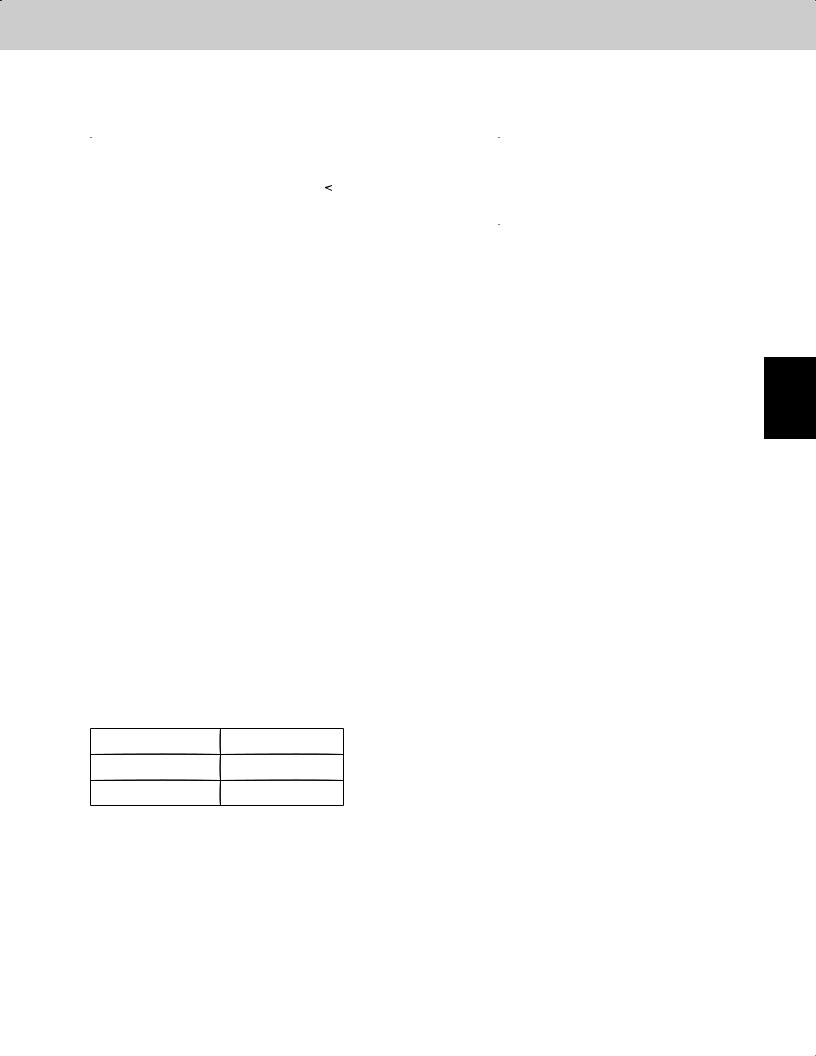
Mini VRF is a multi system that is connected to a single outdoor unit. The outdoor unit contains an inverter compressor.
To operate this system, the below settings must be made at the time of the test run.
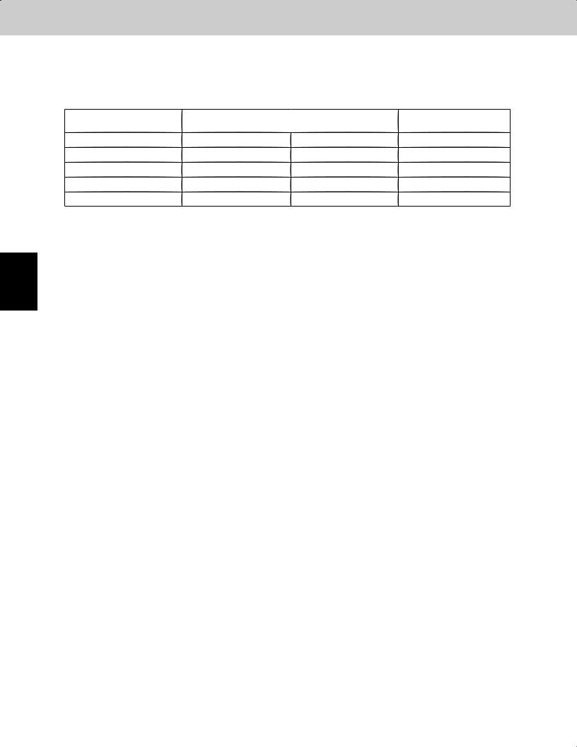
Table 1-1 |
|
|
|
Setting item |
At shipment |
Settable range |
|
from factory |
|||
|
|
||
System address |
1 |
System 1 – 30 |
|
No. of indoor units |
1 |
1 – (15) units * |
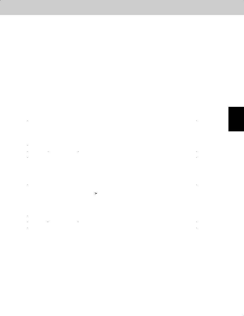
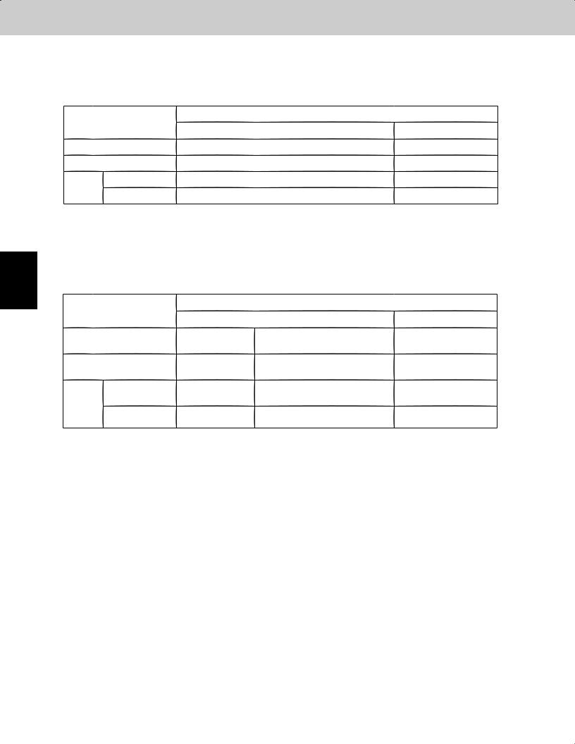
*Up to a maximum of 15 indoor units can be set, however the maximum number of units which can be connected is shown below for each outdoor unit capacity.
Table 1-2 |
|
|
|
|
4HP |
5HP |
6HP |
Maximum number of connected indoor units |
6 |
8 |
9 |
Be sure to connect indoor units so that the resulting indoor-outdoor capacity ratio (total capacity of all indoor units compared with the outdoor unit capacity) is within the range of 50% – 130%.
1 - 2

2. Compressor Control |
|
|
Mini VRF SYSTEM |
|
|
|
Control Functions |
||
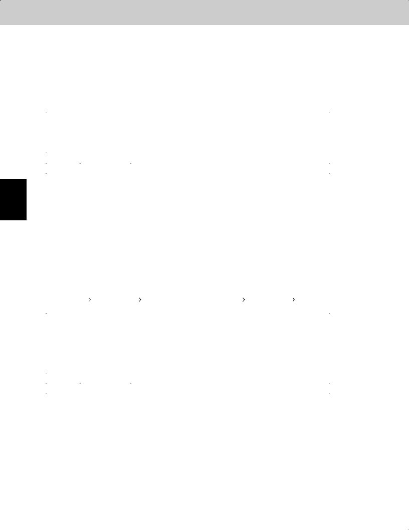
2-1. Compressors Mounted on Outdoor Units |
|
|
||
Capacity |
Type |
4HP |
5HP |
6HP |
Compressors mounted |
Rotary |
|
DC Inverter |
|
2-2. Compressor Stop Rules
After a compressor stops, it will not start again for a period of 3 minutes (3 minutes forced OFF). However, this does not apply to the Special Control described later, when operation of the compressor is forcibly stopped as part of a control operation.
2-3. Roadmap Control
(1)The controls listed below are performed according to the pressure sensor attached to the outdoor unit and temperature thermistor attached to the indoor / outdoor unit heat exchanger.
*With roadmap control, the pressure detected by the pressure sensor is converted to saturation temperature before it is used. The temperature that has been converted to the saturation temperature is called the pressure sensor temperature.
(2)This control is performed every 30 seconds.
(3)In the evaporation temperature control and condensation temperature control shown in Figs. 1-1 and 1-2, the temperatures used to judge each area (A, AB, B, and C) may vary depending on the relationships among factors including the difference between the room temperature setting and the indoor unit air intake temperature (= air intake temperature difference) and the difference between the air discharge temperature setting and the air discharge temperature (= air discharge temperature difference).
(4)Definitions of the evaporation temperature and condensation temperature
Evaporation temperature (=Te) : Lowest temperature of the heat exchangers (E1, E3) in all indoor units.
Condensation temperature (=Tc) : The value used for judgment in Cooling mode and Heating mode is different depending on the mode.
Cooling mode |
: The outdoor unit pressure sensor temperature or the outdoor unit heat |
|
exchanger liquid temperature, whichever temperature is higher. |
Heating mode |
: The outdoor unit pressure sensor temperature or the indoor unit heat |
|
exchanger temperature (E1) when the heating thermostat is ON, whichever |
|
temperature is higher. |
*The E3 temperature may indicate the temperature of superheated gas. Therefore it is not included for detection of the condensation temperature (=Tc).
1
2
3
4
5
6
1 - 3

2. Compressor Control
Mini VRF SYSTEM
Control Functions
2-3-1. Roadmap control in cooling mode
With this control, the below evaporation temperature control and condensation temperature control are both used. Control is performed according to the following order of priority:
Control order of priority |
Area C > Area B > Area A |
Example: When Evaporation temperature control = Area A, and Condensation temperature control = Area C, then based on the above order or priority, the result is “Area C = Reduce horsepower.”
Evaporation temperature (=Te) control
|
|
Horsepower increase permitted |
(Area A) |
|
41.1°F |
|
|
|
41.0°F |
|
|
1 |
|
Horsepower increase prohibited |
(Area B) |
35.6°F |
|
|
|
|
|
|
|
|
35.4°F |
Horsepower decrease |
(Area C) |
|
|
|
|
|
Fig. 1-1 |
2 |
(1) For indoor units that are operating in Cooling mode, if one unit is selected for a test run, then the air intake |
temperature difference (difference between the room temperature setting and indoor unit air intake tempera- |
ture) is ignored, and areas B and C are considered to be area A for control purposes. (This is used for additional refrigerant charging, test run checks, etc.)
For this reason, vapor may be discharged if the test run continues for a long period of time, however this does not indicate a problem. In addition, the test run is canceled automatically after 1 hour.
3
4
(2) |
Even within the same area, the compressor capacity varies depending on the refrigerant temperature. |
(3) |
For 6 minutes after the compressors start, area C is considered to be area B for control purposes. |
(4) |
During special control, control of the compressor capacity according to Te is not performed. |
(5) |
If the thermostat turns OFF while Te is within area C, the next time the compressor starts it may restart from a |
|
lower capacity. |
(6)When the area changes to area C, area C is considered to be area B for control purposes for the first 6 minutes, even if the horsepower is the minimum value within the range where capacity control is possible (operation with inverter frequency of 25 Hz only). Subsequently if C area continues, the thermostat turns OFF.
5 |
Condensation temperature (=Tc) control |
|
|
|
|
||
|
|
Thermostat OFF |
(Area D) |
|
|
||
|
133.7°F |
|
|
|
|
||
|
|
|
|
6 |
133.5°F |
|
|
|
Horsepower decrease |
(Area C) |
|
|
|
||
|
126.6°F |
|
|
|
|
|
|
|
126.5°F |
|
|
|
|
Horsepower increase prohibited |
(Area B) |
|
124.7°F |
|
|
|
124.5°F |
Horsepower increase permitted |
(Area A) |
|
|
|
|
Fig. 1-2
1 - 4
2. Compressor Control |
Mini VRF SYSTEM |
Control Functions |
2-3-2. Roadmap control in heating mode
Roadmap control is performed using the below condensation temperature control.
Condensation temperature (=Tc) control
|
Thermostat OFF |
(Area D) |
|
|
|
133.7°F |
|
|
133.5°F |
|
|
|
Horsepower decrease |
(Area C) |
123.9°F |
|
|
123.8°F |
|
|
|
Horsepower increase prohibited |
(Area B) |
120.2°F |
|
|
120.0°F |
Horsepower increase permitted |
(Area A) |
|
|
|
Fig. 1-3
(1)For indoor units that are operating in Heating mode, if one unit is selected for a test run, the air intake temperature difference is ignored; however, Tc control is performed according to Fig. 1-3 in order to prevent excessive load. (This is used for test run checks, etc.)
(2)Even within the same area, the compressor capacity varies depending on the refrigerant temperature.
(3)If the condensation temperature (Tc) enters area D and the thermostat turns OFF, the next time the compressor starts it may restart from a lower capacity.
(4)When the area changes to area C, area C is considered to be area B for control purposes for the first 6 minutes, even if the horsepower is the minimum value within the range where capacity control is possible (operation with inverter frequency of 25 Hz only). Subsequently if C area continues, the thermostat turns OFF.
2-3-3. Protection control
Protection control consists of 2 types of protection: compressor air discharge temperature protection and current protection. The limit values from this protection control are incorporated into the output compressor capacity increase/decrease values that were calculated from roadmap control.
*In some cases, the control shown below may stop the compressor, issue an alarm, or reduce the compressor capacity.
(1)Air discharge temperature protection
The compressor capacity is limited by using the air discharge temperature of the operating compressor (as shown in the tables below).
(Air discharge temperature level: Highest level among the air discharge temperature levels of all compressors)
Air discharge |
Horsepower (hp) limits |
|
temperature level |
||
|
||
|
|
|
221 |
+2 hp down |
|
|
|
|
219 |
+1 hp down |
|
|
|
|
215 |
+0.5 hp down |
|
|
|
|
210 – Less than 215 |
Hp increase prohibited |
|
|
|
|
204 – Less than 210 |
Hp increase permitted (slowly) |
|
|
|
|
Less than 204 |
No restriction |
|
|
|
The values shown in the table above are reduced to the values calculated by roadmap control.
1
2
3
4
5
6
1 - 5
2. Compressor Control
Mini VRF SYSTEM
Control Functions
(2)Current protection
Inverter compressor current control is composed of primary current control and secondary current control. Current protection control for the inverter compressor is performed by self-protection in the inverter circuit, and is not based on a calculated increase/decrease in compressor capacity.
|
Primary current |
Secondary current |
|
|
Control |
Control |
|
Compressor |
4 / 5 HP |
6 HP |
Secondary current |
Stop |
More than 25.0 A |
More than 29.5 A |
More than 32.5 A |
Hz Down |
23.5 A – Less than 25.0 A |
28.0 A – Less than 29.5 A |
25.0 A – Less than 32.5 A |
Hz Not_up |
22.5 A – Less than 23.5 A |
27.0 A – Less than 28.0 A |
24.0 A – Less than 25.0 A |
Follows normal operation |
Less than 22.5 A |
Less than 27.0 A |
Less than 24.0 A |
2-4. Roadmap Control After Trip
When restarting after trip-stop occurs, the horsepower may increase slowly depending on the trip counter value.
(1)If trip counter = 1, the horsepower increases at a speed that is 1/2 of ordinary roadmap control.
1(2) If trip counter = 2, the horsepower increases at a speed that is 1/3 of ordinary roadmap control. The trip counter is cleared if no trip occurs within 10 minutes after operation starts.
2
3
4
5
6
1 - 6
3. Special Controls |
Mini VRF SYSTEM |
Control Functions |
In addition to ordinary heating and cooling operation, this system also includes the following 4 types of special controls for control of the system as a whole:
3-1. 4-way valve switching control
3-2. Reverse cycle start control
3-3. Inter systems refrigerant oil recovery control
3-4. Reverse cycle defrost control
3-1. 4-way Valve Switching Control
4-way valve switching control is performed under the following conditions:
•The indoor unit operating mode has been switched (Cooling mode / Heating mode).
•The power is turned ON and the microcomputer has been initialized.
•Reverse cycle start control has ended.
This control is performed in order to ensure reliable switching of the 4-way valve. It also performs control to compensate for tubing heat radiation loss when heating starts after the outdoor unit was stopped for a long time, and control for oil recovery.
(1) Control when the outdoor unit heat exchanger is functioning as a condenser (indoor unit mode = Cooling)
Control time |
1 minute |
||
|
|
|
|
Outdoor units |
Operates at a compressor frequency of 44 Hz. |
||
|
|
|
|
|
Electronic |
All indoor units operate at a fixed pulse according to the indoor |
|
Indoor |
control valve |
unit capacity. |
|
units |
|
|
|
Fan |
The fan operates at the set fan speed, is stopped, or operates at |
||
|
|||
|
“L” fan speed, according to the operation mode of the indoor unit. |
||
|
|
||
|
|
|
|
*When the above operation is finished, normal operation starts at the horsepower determined by the indoor units where thermostats are ON.
(2) Control when outdoor unit heat exchanger is functioning as an evaporator (indoor unit mode = Heating)
Control time |
Min. 1 minute to Max. 5 minutes |
||||
(until Tc |
|
95°F) |
|||
|
|
|
|||
|
|
|
|||
|
|
|
|
|
|
Outdoor units |
Operates at a compressor frequency of 44 Hz. |
||||
|
|
|
|
|
|
|
Electronic |
All indoor units operate at 480 pulses. |
|||
Indoor |
control valve |
||||
|
|
|
|||
units |
Fan |
The fan stops. |
|||
|
|||||
|
|
|
|
|
|
*When the above operation is finished, normal operation starts at the horsepower determined by the indoor units where thermostats are ON.
1
2
3
4
5
6
1 - 7
1
2
3
4
5
6
3. Special Controls |
Mini VRF SYSTEM |
Control Functions |
3-2. Reverse Cycle Start Control
Reverse cycle start control is performed under the following conditions:
•The outdoor unit starts in Heating mode after microcomputer initialization when the power was turned ON.
•The outdoor unit starts in Heating mode after it was stopped for 1 hour or longer.
When the outdoor unit starts in Heating mode after having been stopped for a long period of time, this control first operates the unit in Cooling mode to return refrigerant from the outdoor unit heat exchanger to the liquid tubing. This prevents back-flow of the refrigerant liquid which had accumulated in the outdoor unit heat exchanger.
Control time |
1 minute |
|
|
|
|
Outdoor units |
Operates at a compressor frequency of 46 Hz. |
|
|
|
|
|
Electronic |
All indoor units operate at a fixed pulse according to the indoor |
Indoor |
control valve |
unit capacity. |
units |
Fan |
The fan operates at the set fan speed, is stopped, or operates at |
|
||
|
“L” fan speed, according to the operation mode of the indoor unit. |
|
|
|
|
|
|
|
3-3. Inter Systems Refrigerant Oil Recovery Control
3-3-1. Inter systems refrigerant oil recovery cycle
In both indoor unit Cooling mode and Heating mode, this control is performed in the cooling cycle after a certain amount of time has passed.
3-3-2. Start of inter systems refrigerant oil recovery control
This control is performed periodically after the total compressor operating time exceeds 150 minutes.
3-3-3. Flow of inter systems refrigerant oil recovery control
(1) Simplified flow of inter systems refrigerant oil recovery control
Inter systems refrigerant oil recovery control follows this flow process:
Normal |
1-minute |
Inter systems refrigerant oil |
1-minute |
Normal |
operation |
stop |
recovery control (3-minute) |
stop |
operation |
|
|
|
|
|
Control time |
3 minutes (stops once before and after control) |
|
||
|
|
|
|
|
|
|
Operates at a compressor frequency of 65 Hz. |
|
|
Outdoor units |
However depending on the operating conditions, the frequency |
|||
|
|
may be lower than this value. |
|
|
|
|
|
||
|
Electronic |
All indoor units operate at a fixed pulse according to the indoor |
||
Indoor |
control valve |
unit capacity. |
|
|
units |
Fan |
The fan operates at the set fan speed, is stopped, or operates at |
||
|
||||
|
“L” fan speed, according to the operation mode of the indoor unit. |
|||
|
|
|||
|
|
|
|
|
3-4. Reverse cycle Defrost Control
3-4-1. Defrost control method
Defrost with this system is done by reverse cycle defrost.
3-4-2. Conditions for start of defrost
Defrost control is started when the “frost detection” conditions are met, and the “defrost mask time” has elapsed.
1 - 8

3. Special Controls |
Mini VRF SYSTEM |
Control Functions |
3-4-3. Frost detection
(a)Frost is not detected at the outdoor unit heat exchanger for 5 minutes after operation starts.
(b)Frost is detected when either Condition 1 or 2 below is met.
|
Heat exchange liquid temperature °F |
|
|
|
|||
Condition 1: |
|
|
Defrosting operation |
|
(The end temperature is |
||
L2 line or below is detected twice, |
42.8 |
end temperature |
|
|
different from the above |
||
|
|
|
detection temperature.) |
||||
|
|
|
|
|
|||
each time continuously for 4 |
–6.5 |
50 |
External temperature °F |
||||
minutes, when the compressor is |
|||||||
|
|
|
|
|
|
||
operating. |
30 |
|
L1 |
||||
|
|
||||||
Condition 2: |
26 |
|
L2 |
||||
17 |
|
|
|
|
|||
L1 line or below is detected for a |
|
|
|
|
|||
|
|
|
|
|
|
||
total of 60 minutes when the |
|
|
14 |
|
|
|
|
compressor is operating. |
|
|
|
|
|
||
|
|
The frost detection area is |
|||||
|
|
|
located under the thick lines |
||||
–9
–13
Fig. 1-4
3-4-4. Defrost mask time
The next defrost operation will not start until the defrost mask time (= 35 minutes) has elapsed following the previous defrost operation.
*While defrost control is in effect, if all indoor units stop, or if the outdoor unit is restarted after it was stopped for protective control or a similar reason, then defrost control may start again after a minimum of 10 minutes.
3-4-5. General flow of reverse cycle defrost
(1)General flow of reverse cycle defrost control
Reverse cycle defrost control follows this flow process:
Normal |
1-minute |
Reverse cycle defrost |
1-minute |
Normal |
operation |
stop |
control (Max. 12-minute) |
stop |
operation |
|
|
|
|
|
Control time |
Max. 12 minutes (stops once before and after control) |
|
||
|
|
|
|
|
Outdoor units |
Operates at a compressor frequency of 75 Hz. |
|
||
The outdoor fan stops. |
|
|
||
|
|
|
|
|
|
|
|
||
|
Electronic |
All indoor units operate at a fixed pulse according to the indoor |
||
Indoor |
control valve |
unit capacity. |
|
|
units |
Fan |
The fan stops. |
|
|
|
|
|
||
|
|
|
|
|
3-4-6. Defrost end judgment conditions
Defrost ends when the below defrost end conditions are met.
Condition 1: Defrost end judgment occurs when the temperature at the temperature sensor installed on the outdoor heat exchanger is 50°F or higher (or has been 42.8°F or higher continuously for 1 minute).
Condition 2: When the maximum defrost time shown in the table above has elapsed, defrost end judgment occurs.
1
2
3
4
5
6
1 - 9
4. Other Control 5. Operation of Solenoid Valves |
Mini VRF SYSTEM |
6. Outdoor Unit Electronic Control Valve (Motor Valve) Control [MOV1] |
Control Functions |
|
|
4. Other Control
4-1. Indoor Unit Self-Separator Oil Recovery Control
Refer to the indoor unit special control item.
5. Operation of Solenoid Valves
5-1. 4-way Valve Control
(1)OFF conditions
•At Cooling mode
•Special control (reverse cycle start control, inter systems refrigerant oil recovery control, reverse cycle defrost control) is in effect.
(2)ON conditions
•At Heating mode
1
2
3
4
6. Outdoor Unit Electronic Control Valve (Motor Valve) Control [MOV1]
6-1. Power Initialization
The valve position is 480 pulses if the indoor unit has not started once after the power was turned ON.
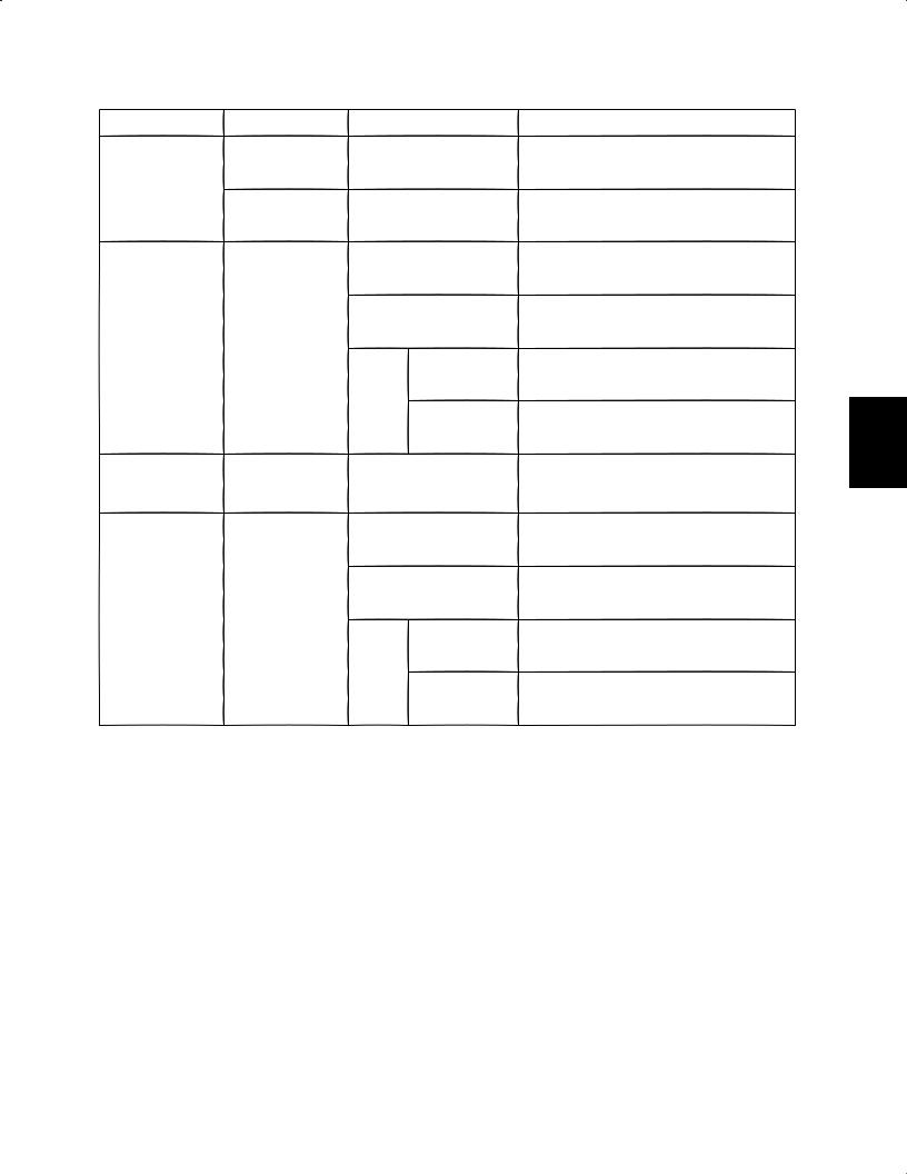
Operation of the electronic control valve during normal unit operation
Indoor Unit |
Heat exchanger status |
MOV1 |
Remarks |
|
|
|
|
Cooling |
Condenser |
480 |
Maximum flow control |
|
|
|
|
operation |
Stop |
480 |
– |
|
|||
|
|
|
|
Heating |
Evaporator |
65 – Less than 480 |
SH (super heat) control |
|
|
|
|
operation |
Stop |
0 |
– |
|
|||
|
|
|
|
*SH control controls the difference between outdoor heat exchanger liquid temperature and suction temperature to 2 – 10°F.
5
6
1 - 10
7. Outdoor Fan Control |
Mini VRF SYSTEM |
Control Functions |
7-1. Outdoor Fan (Min. Fan Mode and Max. Fan Mode)
These outdoor units utilize a DC fan motor that can be controlled using a maximum of 15 increments (15 fan modes).
Outdoor unit |
Min. fan mode |
Max. fan mode |
||
|
|
|
|
|
Cooling operation |
Outdoor air temp. > 86°F: 3 |
14 |
||
Outdoor air temp. |
|
86°F: 1 |
||
|
|
|
||
|
|
|
||
|
|
|
|
|
Heating operation |
21 |
|
|
4 |
|
|
|
|
|
7-2. Fixed Initial Fan Mode
For the first 30 seconds after operation starts, the mode is fixed at the initial mode that was calculated based on the relationship between the outdoor air temperature and the outdoor unit horsepower.
If the outdoor unit horsepower changes dramatically, the initial mode may be recalculated and may be again fixed for 30 seconds.
7-3. Operation after initial fan mode is fixed
After the fixed initial fan mode, the fan mode is increased or decreased according to the operating conditions.
(1)Indoor cooling operation
(a)The fan mode is increased when the pressure sensor temperature is high, and is decreased when the pressure sensor temperature is low.
*The fan mode is always increased when the pressure sensor temperature is 122°F or higher.
(b)The fan mode may be decreased when symptoms of insufficient gas are detected at an indoor unit.
(2)Indoor heating operation
(a)If the condensation temperature is low, the fan mode is increased at regular intervals.
(b)If the condensation temperature is high, the fan mode is decreased in order to prevent excessive load.
(c)The fan mode may be increased when the outdoor liquid temperature drops to 44°F or below.
7-4. When Compressor Magnet Switch Seizing Alarm Occurs
Because the high pressure may increase, operation occurs at the maximum fan mode.
• Quiet mode operation
For the setting procedure, refer to the separate instructions. When Quiet mode is activated, the maximum fan mode is reduced compared to maximum fan mode during normal operation.
Outdoor unit |
Max. fan mode |
Cooling operation |
12 (*14) |
Heating operation |
12 |
*However, during cooling operation if the outdoor air temperature is 91°F or higher, the maximum fan mode is 14.
1
2
3
4
5
6
1 - 11
1
2
3
4
5
6
8. Indoor Unit Electronic Control Valve Control |
Mini VRF SYSTEM |
Control Functions |
INDOOR UNIT
8-1. During Normal Control
(1) During Cooling mode operation
|
|
Electronic control valve position (pulses) |
|
|
Outdoor unit operating |
Outdoor unit stopped |
|
Stop |
20 pulses |
|
20 pulses |
Fan |
20 pulses |
|
20 pulses |
Thermostat OFF |
20 pulses |
|
20 pulses |
Cooling |
|
|
|
Thermostat ON |
55 – 480 pulses |
Performs SH control |
— |
*The target value for SH control is 4 – 12°F for the temperature difference between E3 and E1, depending on the operating conditions.
However, the SH target value may increase if the required level decreases. In this case, because the electronic control valve position moves toward the closed side, you should not assume that there is insufficient gas.
(2)During Heating mode operation
|
|
|
Electronic control valve position (pulses) |
||
|
|
Outdoor unit operating |
Outdoor unit stopped |
||
Stop |
55 |
– 80 pulses |
Control to prevent refrigerant |
85 pulses |
|
accumulation |
|||||
|
|
|
|||
Fan |
55 |
– 80 pulses |
Control to prevent refrigerant |
85 pulses |
|
accumulation |
|||||
|
|
|
|
||
Thermostat OFF |
55 |
– 80 pulses |
Control to prevent refrigerant |
85 pulses |
|
accumulation |
|||||
Heat |
|
|
|
||
|
|
|
|
||
Thermostat ON |
55 |
– 480 pulses |
Performs SC distribution control |
— |
|
*The target value for SC control is 10 – 40°F for the temperature difference between the pressure sensor temperature and E1, depending on the operating conditions.
1 - 12
8. Indoor Unit Electronic Control Valve Control |
Mini VRF SYSTEM |
9. Indoor Special Control |
Control Functions |
8-2. During Special Control
Control type |
Operating mode |
Target indoor units |
|
Cooling |
All indoor units |
4-way valve |
|
|
switching control |
|
|
|
Heating |
All indoor units |
|
|
OFF |
|
|
Fan |
Reverse cycle |
Heating |
|
start control |
|
|
|
|
|
|
|
Thermostat ON |
|
|
Heating |
|
|
Thermostat OFF |
Inter systems |
|
|
refigerant oil |
Cooling / Heating |
All indoor units |
recovery control |
|
|
|
|
OFF |
Fan
Reverse cycle |
Heating |
|
defrost control |
||
|
Thermostat ON
Heating
Thermostat OFF
Electronic control valve position (pulses)
Fixed pulses for cooling, corresponding to the indoor unit capacity
480
Fixed pulses, corresponding to the indoor unit capacity
Fixed pulses, corresponding to the indoor unit capacity
Fixed pulses, corresponding to the indoor unit capacity
Fixed pulses, corresponding to the indoor unit capacity
Fixed pulses, corresponding to the indoor unit capacity
Fixed pulses, corresponding to the indoor unit capacity
Fixed pulses, corresponding to the indoor unit capacity
Fixed pulses, corresponding to the indoor unit capacity
Fixed pulses, corresponding to the indoor unit capacity
9. Indoor Special Control
9-1. Indoor Unit Thermostat ON/OFF Delay Timer
(1)When an indoor unit thermostat turns ON, the thermostat cannot be turned OFF by the room temperature thermostat discharge temperature thermostat for 3 minutes.
However, if the condensation temperature (refrigerant temperature detected at the condenser) reaches PX temperature or higher, the thermostat may turn OFF in order to prevent excessive loads.
(2)When an indoor unit thermostat turns OFF, it will not turn ON again for a minimum of 3 minutes.
9-2. Indoor Unit Refrigerant Oil Self-recovery Control
* This control is performed constantly during Cooling mode operation only.
(1)The electronic control valve at indoor units that are stopped, or are in Fan mode or in Cooling mode with thermostat OFF, opens for 1 – 2 minutes.
(2)At indoor units that are in Cooling mode with thermostat ON, the electronic control valve opens from its current position by approximately 20 pulses.
1
2
3
4
5
6
1 - 13
10. Discharge Gas Temperature |
Mini VRF SYSTEM |
11. Current Protection |
Control Functions |
10-1. Discharge Gas Temperature Protection
Alarm
The compressor upper-limit discharge temperature is 222°F. If the discharge temperature reaches 222°F, then the compressor stops. If the discharge temperature reaches 222°F 4 times repeatedly after restart, an alarm occurs. After the compressor stops, if the discharge temperature at the stopped compressor is at or above 213°F, the compressor start restriction temperature, then this compressor does not operate until the temperature drops.
List of discharge temperature protections
Compressor |
Compressor |
|
Compressor |
|
|
Stop temperature (°F) |
start restriction |
Alarm display |
|||
model |
type |
||||
|
temperature (°F) |
|
|||
|
|
|
|
||
Compressor 1 |
Inverter |
222 |
213 |
P03 |
10-2. Control For Detection of Discharge Sensor Failures
•If the temperature is at or above sensor failure temperature (176°F) (value in parentheses) 60 minutes after the compressor stopped, an alarm occurs.
1• If the discharge gas temperature remains at or above sensor failure temperature (213°F) for 20 minutes after the system is stopped, an alarm occurs.
*In this case, in addition to sensor failure, compressor overheating caused by insufficient refrigerant is also a possibility.
List of discharge sensor failures
2
Compressor |
Compressor |
Alarm display |
|
model |
type |
||
|
3
4
5
Compressor 1 |
Inverter |
F04 |
11. Current Protection
11-1. Fan Motor
Alarm |
Description |
P22
Occurs when the fan motor detects overcurrent, or when the fan motor is locked and does not turn.
6
1 - 14
11. Current Protection 12. Pressure Sensor Failure |
Mini VRF SYSTEM |
13. 4-Way Valve Failure [L18] |
Control Functions |
|
|
11-2. Inverter Compressor
Alarm |
Description |
P16
Occurs when overcurrent (32.5 A) is detected during normal operation.
P26
Occurs under the same conditions as P16, when the inverter compressor is operating at 80 Hz or higher.
P29
Occurs when a missing phase or overcurrent (48 A) is detected when the inverter compressor starts.
H31
Occurs when the HIC detects overcurrent (75 A), and when an abnormal temperature (302°F) is reached.
The inverter current values include primary current and secondary current.
Alarm judgment uses both of these current values. However, in general the secondary current is higher than the primary current.
11-3. CT Circuit Detection Failure
|
Alarm |
Description |
|
Compressor 1 |
H03 |
Occurs when an open circuit is detected in the inverter |
|
(inverter compressor) |
compressor CT circuit. |
||
|
If the operating frequency of the inverter compressor is low, the current value is also low.
As a result, this alarm is detected only when the compressor is stopped.
12. Pressure Sensor Failure
This system includes a high-pressure sensor.
12-1. High-Pressure Sensor Failure
Connector disconnection or displacement failure is judged according to the relationship between the high-pressure sensor temperature, which is detected by the high-pressure sensor, and the various temperature thermistors. However, if the pressure rises suddenly, a high-pressure sensor failure warning may be judged before the highpressure sensor activates. Therefore check the following before determining that a pressure sensor failure has occurred:
•Has the service valve been left open?
•Is there a blocked circuit?
•Is there leakage of refrigerant into stopped outdoor units?
Also check the difference between the high-pressure as measured by a manifold gauge and the pressure as detected by the pressure sensor.
Alarm |
Description |
F16 |
High-pressure sensor failure |
13. 4-Way Valve Failure [L18]
When a 4-way valve coil failure, coil disconnection or similar failure occurs, a judgment is made automatically from the operating conditions, and an alarm is output.
1
2
3
4
5
6
1 - 15
14. Servicing and Maintenance Functions
Mini VRF SYSTEM
Control Functions
The below functions are available, and are selected by the outdoor unit EEPROM settings.
14-1. Outdoor Unit Noise Countermeasures (outdoor Quiet mode function)
This function reduces the operating noise to lessen the noise produced by the outdoor unit. When this mode is selected, noise reduction is given priority during operation, and the outdoor fan mode and compressor operating frequency are restricted (to approximately 80% of capacity).
The following two operations are required in order to engage this mode. (This mode cannot be engaged when neither (1) nor (2) below has been completed.)
(1)Outdoor unit EEPROM settings
Outdoor unit EEPROM 05 can be set from 0 to 1.
EEPROM |
Max. fan |
Effect |
Capacity ratio |
|
setting |
mode |
|||
|
|
|||
|
|
|
|
|
0 |
14 |
Normal operation (setting at time of factory shipment) |
100% |
|
|
|
|
|
|
1 |
12 |
Noise reduced by approx. 3 dB from the catalog value. |
Approx. 80% |
|
|
|
|
|
1
2
3
(2)Short-circuit the “SILENT” 2P pin on the outdoor unit PCB.
Noise reduction mode is engaged constantly when this pin is short-circuited. To operate in noise reduction mode only at night, or for similar control at other times, use an external timer (field supply).
14-2. Slime Countermeasure: EEPROM 0C (set only on the main unit)
This setting controls the operation of the drain pump.
EEPROM
Details of operation
setting
0Normal operation (setting at time of factory shipment)
1Drain pump operates for 20 minutes at 2-hour intervals
2Drain pump operates for 20 minutes, at intervals of 20 minutes
3Drain pump operates continuously
14-3. Delayed Start for Each System: Outdoor EEPROM 3E
The operation start time can be delayed according to the set system addresses.
This setting reduces voltage drops by preventing multiple systems from starting at the same time when operation is 4 restarted after recovery when multiple operating systems were stopped due to a power outage or other cause.
EEPROM
Effect
setting
5
6
0Delayed start is not performed (setting at time of factory shipment)
1System address: Delay in seconds before start
2Start after System address × 2 seconds
3Start after System address × 3 seconds
<Reference> Indoor unit discharge temperature control
Operating mode |
Cooling |
Heating |
Discharge temperature control value |
53 |
122 |
|
Enter shift value |
Enter shift value |
Change method |
for indoor EEPROM |
for indoor EEPROM |
|
setting “1C.” |
setting “1D.” |
The method is the same as ordinary indoor unit discharge temperature shift.
1 - 16

Contents |
Mini VRF SYSTEM |
Outdoor Unit Repair Procedures |
2. OUTDOOR UNIT REPAIR PROCEDURES
Layout Diagram: Sensors and Solenoid Valves . . . . . . . . . . . . . . . . . . . . . . . . . . . . . . . . . 2-2
Layout Diagram: Sensors . . . . . . . . . . . . . . . . . . . . . . . . . . . . . . . . . . . . . . . . . . . . . . . . . . 2-3
1. Removing Panels . . . . . . . . . . . . . . . . . . . . . . . . . . . . . . . . . . . . . . . . . . . . . . . . . . . . . . . 2-4
2. Discharging Oil in Compressor . . . . . . . . . . . . . . . . . . . . . . . . . . . . . . . . . . . . . . . . . . . . 2-5
3. Recovering Refrigerant . . . . . . . . . . . . . . . . . . . . . . . . . . . . . . . . . . . . . . . . . . . . . . . . . . 2-6
4. Checking for Leakage After Repair . . . . . . . . . . . . . . . . . . . . . . . . . . . . . . . . . . . . . . . . 2-11
5. Evacuating System . . . . . . . . . . . . . . . . . . . . . . . . . . . . . . . . . . . . . . . . . . . . . . . . . . . . . 2-12
6. Charging Compressor Oil . . . . . . . . . . . . . . . . . . . . . . . . . . . . . . . . . . . . . . . . . . . . . . . 2-13
7. Pumping Out Refrigerant from Outdoor Unit . . . . . . . . . . . . . . . . . . . . . . . . . . . . . . . . 2-17
8. Compressor . . . . . . . . . . . . . . . . . . . . . . . . . . . . . . . . . . . . . . . . . . . . . . . . . . . . . . . . . . 2-19
9. High Pressure Sensor . . . . . . . . . . . . . . . . . . . . . . . . . . . . . . . . . . . . . . . . . . . . . . . . . . 2-22
1
2
3
4
5
6
2 - 1

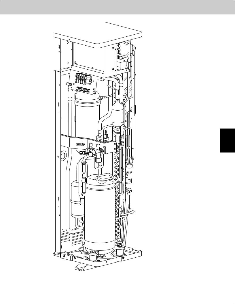
Layout Diagram: Sensors and Solenoid Valves
Mini VRF SYSTEM
Outdoor Unit Repair Procedures
1
2
3
4
5
6
TS
(suction thermistor)
MOV
(electronic motor-operated valve)
20S
(4-way valve)
C1
(condenser 1 thermistor)
2 - 2
Layout Diagram: Sensors
Mini VRF SYSTEM
Outdoor Unit Repair Procedures
TS
 (suction thermistor)
C1
 (condenser 1 thermistor)
1
2
3
4
5
6
2 - 3
1. Removing Panels
Mini VRF SYSTEM
Outdoor Unit Repair Procedures
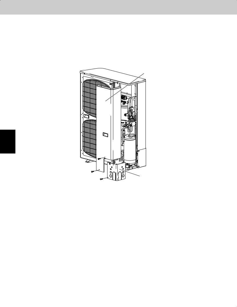
(1)Front panel removal (Fig. 2-1)
•Remove the front panel (remove 3 screws).
(2)Cover A removal (Fig. 2-1)
•Remove the cover A (remove 1 screw).
1
2
3
4
5
6
Front panel
Cover A
Fig. 2-1
2 - 4

2. Discharging Oil in Compressor
Mini VRF SYSTEM
Outdoor Unit Repair Procedures
Recover the refrigerant in the outdoor unit following the procedures in “3. Recovering Refrigerant.” Remove the compressor and discharge the oil in it. Refer to “8. Compressor” for detailed procedures.
2-1. Checking the Oil
Acceptance/rejection criteria for the oil
Condition of |
|
Condition of oil |
Judgment criteria for changing oil* |
||
refrigeration cycle |
Color |
|
Odor |
Total acid value |
Hue |
|
|
|
|
|
|
Normal |
Yellowish |
|
None |
0.02 or less |
3.5 or less |
|
|
|
|
|
|
Abnormal overheat- |
|
|
Smells somewhat |
0.06 or over |
4.0 or over |
Brownish |
|
|
|
||
|
Changing the oil and system cleaning |
||||
operation |
|
(not as strong as below) |
|||
|
|
with dry-cores are necessary. |
|||
|
|
|
|
||
Motor burnout |
Brownish / |
|
Pungent / burnt odor |
Changing the oil and system cleaning |
|
blackish |
|
with dry-cores are necessary. |
|||
|
|
|
|||
*It is difficult to measure the total acid value in the field, therefore oil hue and odor are the rule of thumb. Checking for carbon deposits and abrasive metal powder can additionally be used to assess the system condition.
1
2
3
4
5
6
2 - 5
1
2
3
4
5
6
3. Recovering Refrigerant |
Mini VRF SYSTEM |
Outdoor Unit Repair Procedures |
The following equipment and tools are required:
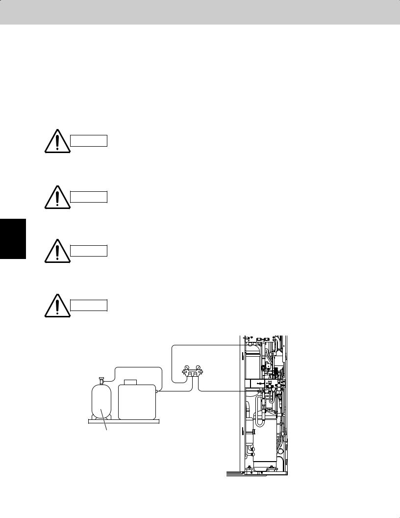
Jumper wire with clips, adjustable wrench, set of manifold gauge valves specially designed for refrigerant R410A only, vacuum pump, refrigerant recovery unit, pre-purged refrigerant cylinder for recovery (air already evacuated), and hex wrench (4 mm for liquid tube and 5 mm for gas tube).
3-1. Refrigerant Recovery Procedures (From Outdoor Unit)
(1)Turn off the power of the outdoor unit beforehand (at power mains).
(2)Fully close each service valve on the gas line and liquid line of the outdoor unit.
(3)Connect the outdoor unit’s high-pressure and low-pressure outlet ports with the Hi and Lo sides of the manifold gauge valves using hoses. (See Fig. 2-2)
The remaining refrigerant in the outdoor unit may create internal pressure.
CAUTION Before connecting hoses, be sure to confirm that each of the manifold gauge valves is tightly closed. Note that the connection ports employ Schrader-type,
press-to-release valves.
(4) Connect the manifold gauge valves, refrigerant recovery unit, and recovery cylinder using hoses. To avoid the entry of air into the refrigerant tubing, carry out this connection work carefully.
For detailed procedures such as connecting the refrigerant recovery unit
CAUTION with the recovery cylinder and methods used for recovery, follow the specific instructions that came with the refrigerant recovery unit.
(5) Locate the AP pins on the control PCB in the outdoor unit and short them using the clips of the jumper wire. Then restore electrical power to the outdoor unit.
By short-circuiting the AP pins, each electronic expansion valve in the
CAUTION outdoor unit is forcibly opened as soon as power comes on, which releases all remaining refrigerant into the recovery cylinder. Since neglecting this
procedure may leave some refrigerant in the system, it is important that you carry out this step.
(6) Carry out refrigerant recovery.
CAUTION |
To determine the completion of refrigerant recovery, follow the instructions |
||
that came with the refrigerant recovery unit. |
|||
|
|||
|
|
Low-pressure outlet port |
|
|
|
(For ø5/16" connector) |
|
|
Manifold |
||
|
|
gauge |
|
|
Lo |
Hi |
|
 Refrigerant
recovery unit
Refrigerant recovery cylinder
Fig. 2-2
2 - 6
3. Recovering Refrigerant |
Mini VRF SYSTEM |
Outdoor Unit Repair Procedures |
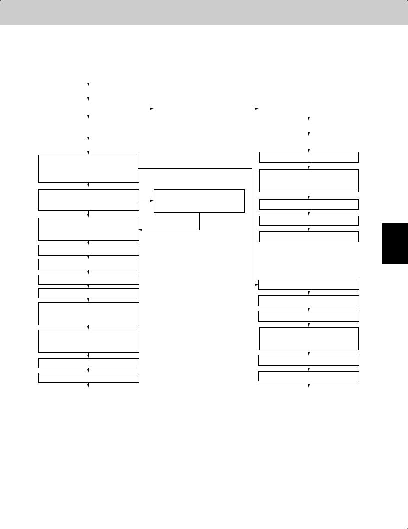
3-2. Refrigerant Recovery Procedures (Indoor Unit)
The flowchart below shows the refrigerant recovery procedures you must follow when replacing or repairing the indoor unit due to trouble in the refrigerant circuit.
START |
|
|
|
|
|
|
|
||
|
|
|
|
|
|
|
|
||
|
|
|
|
|
|
|
|
||
3-2-1. Cooling operation (for all units) |
|
|
|
|
|
|
|
||
|
|
|
|
|
|
|
|
||
|
|
|
|
|
|
|
|
||
Ball valve is provided in the indoor unit |
|
|
3-2-3. Refrigerant recovery |
|
|
Turn off all equipment in system |
|||
|
|
|
NO |
|
|
|
|||
|
|
YES |
|
procedures (2) |
|
|
|
|
|
3-2-2. Refrigerant recovery |
|
|
|
|
|
Replace or repair faulty unit |
|||
procedures (1) |
|
|
|
|
|
||||
|
|
|
|
|
|
|
|||
|
|
|
|
|
|
|
|||
|
|
|
|
|
|
|
|
|
|
|
|
|
|
|
|
|
|
Check for leakage in repaired unit |
|
Turn off all equipment in system |
|
|
|
|
|
||||
|
|
|
|
|
|
|
|||
When replacing or repairing a faulty |
|
|
Evacuate air from repaired unit |
|
|
|
|
||
unit, let other normal indoor units run |
|
|
|
|
(excluding indoor unit where refrigerant |
NO |
|
Charge refrigerant in repaired unit |
|
is recovered) |
|
|||
|
|
(Amount of charge should equal that |
||
YES |
|
|
||
|
|
recovered by refrigerant recovery unit) |
||
Power can independently be turned off |
|
Modify power to permit turning off |
|
|
for indoor unit where refrigerant is |
|
power to refrigerant-recovered |
Open ball valve |
|
recovered |
NO |
indoor units independently |
||
|
||||
YES |
|
|
|
|
Change controllable number of indoor |
|
|
Ready for operation |
|
|
|
|
||
units (including changes in group |
|
|
|
|
control and integrated-control settings) |
|
|
END |
|
Other indoor units can operate normally |
|
|
|
|
Replace or repair faulty unit |
|
|
|
|
Check for leakage in repaired unit * |
|
|
Replace or repair faulty unit |
|
|
|
|
Evacuate air from repaired unit *
Charge refrigerant in repaired unit *
(Amount of charge should equal that recovered by refrigerant recovery unit)
Change controllable number of indoor units (including changes in group control and integrated-control settings)
Open ball valve
Ready for normal operation
Check for leakage in repaired unit *
Evacuate air in repaired unit *
Charge refrigerant in repaired unit *
(Amount of charge should equal that recovered by refrigerant recovery unit)
Open the ball valve
Ready for normal operation
END |
|
END |
|
|
|
* Service work performed on indoor units is done simultaneously using the service ports at the liquid tube side and the gas tube side ball valves. Refer to each section in the “Installation Instructions” on refrigerant charging, leak checking, and evacuation procedures.
1
2
3
4
5
6
2 - 7
 Loading...