


Panasonic U-96MF1U9, U-72MF1U9, U-72MF1U9E, U-96ME1U9E, U-96ME1U9 Installation Manual
...INSTALLATION INSTRUCTIONS
LonWorks Interface
Model No. CZ-CLNC1U
|
|
–– Contents –– |
1. |
LonWorks Interface Overview |
2 |
|
Product Overview |
|
|
System Diagram |
|
|
Functions |
|
2. |
Installation Instructions of LonWorks Interface |
4 |
|
Safety Precautions |
|
|
Included Parts |
|
|
Installation Method |
|
|
Wiring Specifi cations |
|
|
LonWorks Interface Structure |
|
|
Power Board Initial Settings |
5 |
|
Power Board Wiring |
|
|
Wiring Procedure |
|
|
Main Circuit Board |
|
|
Indoor Unit Enabling Switches |
6 |
|
Setting Switches |
|
|
Address Switches |
|
|
Communications LED (Green) |
7 |
|
Data LED (Red) |
|
|
Diagram of External Dimensions |
|
|
Product Specifi cations |
|
3. |
Assigning Central Control Addresses |
8 |
4. |
LonWorks Interface Test Run |
9 |
5. |
Checking the LonWorks Interface Version |
10 |
6. |
List of LonWorks Network Variables |
11 |
7. |
Details of LonWorks Network Variables |
12 |
8. |
Locations Where Neuron ID is Applied |
15 |
Note:
This equipment has been tested and found to comply with the limits for a Class B digital device, pursuant to part 15 of the FCC Rules. These limits are designed to provide reasonable protection against harmful interference in a residential installation. This equipment generates, uses and can radiate radio frequency energy and, if not installed and used in accordance with the instructions, may cause harmful interference to radio communications. However, there is no guarantee that interference will not occur in a particular installation. If this equipment does cause harmful interference to radio or television reception, which can be determined by turning the equipment off and on, the user is encouraged to try to correct the interference by one or more of the following measures:
•Reorient or relocate the receiving antenna.
•Increase the separation between the equipment and receiver.
•Connect the equipment into an outlet on a circuit different from that to which the receiver is connected.
•Consult the dealer or an experienced radio/TV technician for help.
FCC Caution: To assure continued compliance, follow the attached installation instructions.
Any changes or modifi cations not expressly approved by the party responsible for compliance could void the user’s authority to operate this equipment.
LonWorks is a registered trademark of the Echelon Corporation.
85464369526011
|
|
|
|
|
|
|
|
|
|
|
|
|
|
Pana_CZ-CLNC1U_Eng.indd 1 |
|
2011/11/11 12:23:41 |
|
|
|
|
|
|
|
||||
|
|
|
|
|
|
|
1. LonWorks Interface Overview
Product Overview
This interface is a communications interface for connecting LonWorks to an air conditioner unit control network.
From the host connected to LonWorks, basic settings and status monitoring is possible for up to 16 groups of A/C units.
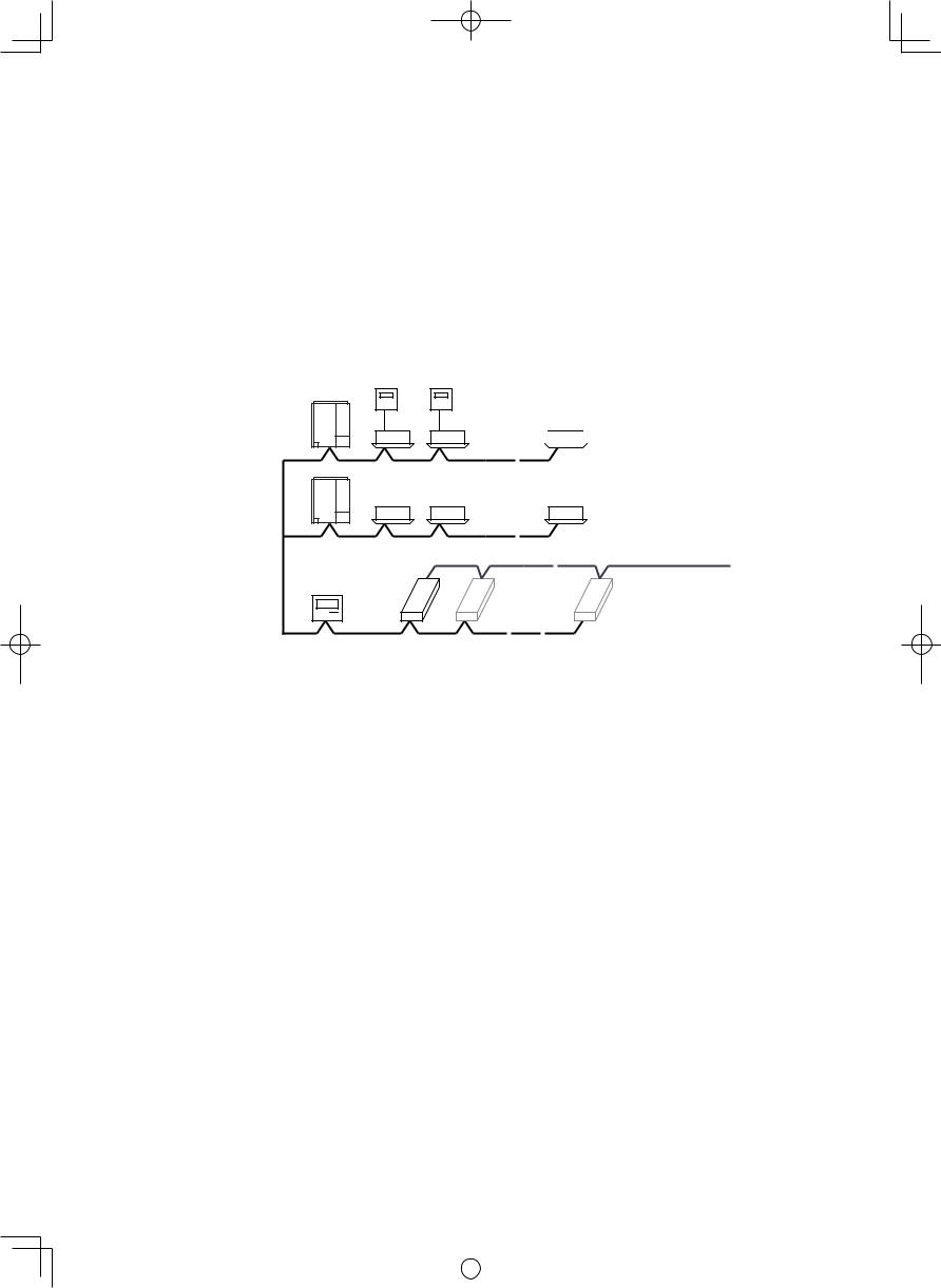
System Diagram
Outdoor
Unit
Outdoor
Unit
 Indoor Unit
Indoor Unit
LonWorks communication line
LonWorks Interface
Inter-unit control wiring
•Up to 16 groups of indoor units (maximum 64 units) can be controlled with 1 LonWorks Interface unit. For 17 or more groups of indoor units, connect additional interface units.
•Install a remote controller (or system controller, etc.), which can control the A/C units, to an inter-unit control wiring other than the LonWorks Interface unit.
•Before making the connection to the LonWorks Interface unit, set the central control addresses in the indoor units.
2
|
|
|
|
|
|
|
|
|
|
|
|
|
|
Pana_CZ-CLNC1U_Eng.indd 2 |
|
2011/11/11 12:23:41 |
|
|
|
|
|
|
|
||||
|
|
|
|
|
|
|
Functions
|
|
Start/stop |
|
|
|
|
|
|
Settings for |
Temp. setting(*1) |
|
A/C unit settings |
|
||
each group of |
Operation mode |
||
from the |
|||
indoor units |
|
||
Option 1 settings(*2) |
|||
LonWorks |
|||
|
|||
|
|
||
|
|
Option 2 settings(*2) |
|
|
|
|
|
|
Settings for all units |
Emergency stop |
|
|
|
|
|
|
|
Start/stop |
|
|
|
|
|
|
|
Temp. setting |
|
|
|
|
|
|
|
Operation mode |
|
|
|
|
|
A/C unit status notifi cations made |
Option 1 settings(*2) |
||
|
|||
Option 2 settings(*2) |
|||
to the LonWorks |
|||
|
|||
Alarm status(*3) |
|||
|
|
||
|
|
|
|
|
|
Indoor units with active alarms(*4) |
|
|
|
|
|
|
|
Room temp(*5) |
|
|
|
|
|
|
|
A/C unit status(*6) |
|
|
|
|
|
|
|
Transmission interval settings(*7) |
|
Confi guration properties |
|
||
Minimum time secured |
|||
|
|
for transmission(*8) |
|
|
|
|
|
(*1) When a temperature above the upper limit of the temperature which can be set by the indoor units has been specifi ed, it will be set to the upper limit; conversely, when a temperature below the lower limit has been specifi ed, it will be set to the lower limit.
(*2) Two options can be selected using the setting switch from among remote-controller prohibit, fan speed setting, air direction setting and fi lter sign.
(*3) When indoor units are under group control, an alarm is determined to have occurred when the alarm occurs at one or more of the units.
(*4) The number of the indoor unit at which the alarm has occurred is notifi ed. This makes it possible to identify at which indoor unit of the indoor unit group the alarm has occurred.
(*5) When indoor units are under group control, the room temperature of the main unit in the group is notifi ed. (*6) When an alarm occurs at one or more indoor units, the alarm code is notifi ed as the indoor unit status. (*7) All the data which can be output is output at the set interval.
(*8) The same data is not output continuously at the set interval.
3
|
|
|
|
|
|
|
|
|
|
|
|
|
|
Pana_CZ-CLNC1U_Eng.indd 3 |
|
2011/11/11 12:23:41 |
|
|
|
|
|
|
|
||||
|
|
|
|
|
|
|
2. Installation Instructions of LonWorks Interface
Safety Precautions
The following is intended for the installer responsible for installation and test operations of the LonWorks Interface, and should be carefully read before beginning.
The precautions given in this manual consist of specifi c “Warnings” and “Cautions.” They provide important safety-related information and are important for your safety, the safety of others, and trouble-free operation of the system. Be sure to strictly observe all safety procedures. The labels and their meanings are as described below.
 Warning
 Caution
This symbol refers to a hazard or unsafe procedure or practice which can result in severe personal injury or death.
This symbol refers to a hazard or unsafe procedure or practice which can result in personal injury or product or property damage.
After installation is completed, perform a test run to check for operating trouble. As you do, use the central control device Operating Instructions and explain operating procedures to the customer. Then request that the customer store this manual together with the central control device
Operating Instructions.
 Warning
•Be sure to arrange installation from the dealer where the system was purchased or using a professional installer. Electric shock or fi re may result if an inexperienced person performs any installation or wiring procedures incorrectly.
•Please install and ensure construction according to Installation Instructions of LonWorks Interface.
•Only a qualifi ed electrician should attempt to connect this system, in accordance with the instructions in this manual. If the electrical circuit capacity is insuffi cient a danger of electric shock and fi re may be present.
•Use the specifi ed cables (type and wiring diameter) for the electrical connections, and connect the cables securely. Run and fasten the cables securely so that external forces or pressure placed on the cables will not be transmitted to the connection terminals. Overheating or fi re may result if connections or attachments are not secure.
 Caution
Depending on the installation conditions and location, an earth leakage breaker may be required. If an earth-leakage breaker is not installed, there is a danger of electric shock or fi re.
Included Parts
No. |
|
|
|
Part |
Qty |
||
(1) |
|
|
|
|
|
|
1 |
|
|
|
|
|
|
||
|
|
|
|
|
|
||
|
Installation Instructions |
|
|||||
|
|
|
|
|
|
|
|
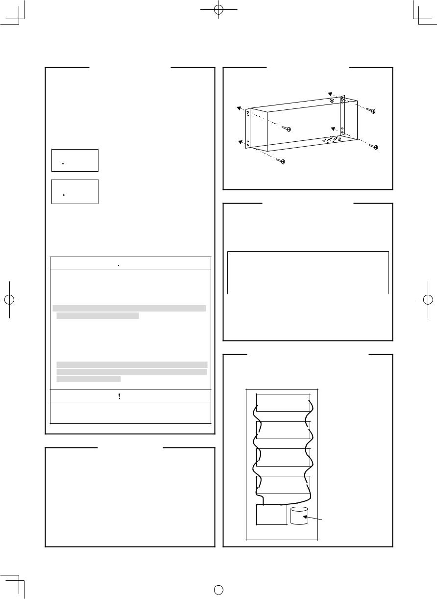
Installation Method
•The screws used to install the main unit must be provided by the installer.
•Install the LonWorks Interface away from any sources of electrical noise.
Wiring Specifications
•For the inter-unit control wiring use twin-core AWG#20 – AWG#14 cables.
•For the LonWorks communication line cables, use twistedpair cables with a wire diameter of 0.51 mm(AWG#24) or larger as recommended by Echelon Corp.
Examples of cables recommended by Echelon Corp.
Cable type |
Wire diameter |
Total cable length |
||
/AWG |
Bus type |
Free |
||
|
||||
|
|
|||
|
|
|
|
|
24 AMG twisted-pair |
0.51 mm |
900 m |
450 m |
|
(TIA568A category 5) |
/24 |
(2953 ft.) |
(1476 ft.) |
|
|
|
|
|
|
•Do not use the same cable for the inter-unit control wiring, the LonWorks communication lines, and the power cable. Do not run them through the same conduit or place the cables near one another.
•Connect the cables so that there is no miswiring. (Miswiring can cause malfunction.)
LonWorks Interface Structure
•This interface contains 4 LonWorks communication boards (nodes).
•Up to 4 indoor unit groups (maximum 32 units) can be assigned to 1 node.
Main circuit board Node 3
Main circuit board Node 2
Main circuit board Node 1
Main circuit board Node 0
Power |
|
board |
Power transformer |
4
|
|
|
|
|
|
|
|
|
|
|
|
|
|
Pana_CZ-CLNC1U_Eng.indd 4 |
|
2011/11/11 12:23:41 |
|
|
|
|
|
|
|
||||
|
|
|
|
|
|
|

Power Board Initial Settings |
Wiring Procedure |
|||
Not Install: Ordinarily, keep this set to “Not Install” (initial setting). |
• Connect the power supply lines to the L and N power supply |
|||
Install: Free topology terminal resistor (51Ω) for the |
terminals. |
|
||
LonWorks communication lines. |
|
(the power suplly neutral to the N terminal.) |
||
Install |
Not Install |
|
• Connect an earth ground line to the screw. |
|
|
|
ON |
|
|
S002 |
|
Power switch |
Lon communication wiring |
|
|
|
|
||
|
S001 |
OFF |
|
|
|
|
|
|
|
Power board |
|
CN006 (when AC 200- |
|
|
CN005 |
240V power is connected) |
|
|
|
|
|
|
||
(when AC 100-120V |
|
|
|
|
power is connected) |
|
Power board |
||
|
|
|
||
|
|
|
L |
N |
100-120/200-240 V |
|
|
|
|
50/60 Hz 1-PH |
|
|
|
|
|
Power transformer primary-side |
|
|
|
|
|
|
|
Conduit (Power cables) |
When AC 200-240V power is connected, connect the power
transformer primary-side to CN006. When AC 100-120V power is Inter-unit control wiring connected, connect the power transformer primary-side to CN005.
(It is connected to CN006 when the unit is shipped from the plant.)
Power Board Wiring |
|
|
Main Circuit Board |
|
|||
|
|
|
|
|
|
S001 |
|
LON communication |
|
|
|
|
|
S002 |
|
6 |
|
|
|
LD001~LD008 |
|
||
lines (2) |
|
|
|
|
|
|
|
|
|
Neuron ID label |
|
|
|||
LON communication |
|
|
|
|
|||
line (2) (reserve) |
CN003 |
|
|
|
|
|
|
LON communication |
Power board |
|
|
|
|
|
|
lines (1) |
|
|
|
Data |
|
||
|
|
|
|
COM |
|
||
LON communication |
1 |
|
|
|
|
||
|
|
|
|
|
|
||
line (1) (reserve) |
3 |
|
|
|
|
|
|
Inter-unit |
|
|
|
|
|
|
|
L |
N |
|
|
|
|
|
|
control lines |
CN002 |
|
|
IC002 |
|
|
|
1 |
|
|
|
|
|||
Inter-unit |
|
|
|
|
|
|
|
|
|
|
|
|
|
|
|
control line (reserve) |
|
|
|
|
|
|
|
Earth for power wiring |
100-120/200-240 V |
|
|
|
|
|
|
|
50/60 Hz 1-PH |
|
|
|
|
|
|
|
|
|
|
S003 |
S005 |
S006 |
|
|
|
|
LD009 |
Address SW |
|
||
• The LonWorks communication lines can be connected |
|
|
|||||
|
|
Setting SW |
|
||||
|
|
S004 |
|
||||
to either (1) or (2) in the above fi gure. The results are the |
|
|
|
|
|||
same. |
|
|
|
|
Indoor unit enabling SW |
|
|
• Do not run the inter-unit control lines, the LonWorks |
|
|
|
|
|
||
communication lines, and the power cables through the |
|
|
|
|
|
||
same conduit, or place the cables near one another. Doing |
|
|
|
|
|
||
so can cause the system to malfunction. |
|
|
|
|
|
|
|
• Before turning the power on, follow the instruction in Power |
|
|
|
|
|
||
Board Initial Settings. |
|
|
|
|
|
|
|
• When using the spare inter-unit cotrol line, connect [1] and [3] |
|
|
|
|
|
||
at CN002. |
|
|
|
|
|
|
|
• When using the spare LON communication line, connect [1] |
|
|
|
|
|
||
and [3] or [4] and [6] at CN003. |
|
|
|
|
|
|
|
|
|
|
|
|
|
5 |
|
Pana_CZ-CLNC1U_Eng.indd 5 |
|
|
|
|
|
2011/11/11 |
12:23:42 |
 Loading...