


 Loading...
Cat.No. W438-E1-01
SYSMAC
WS02-CXPC1-E-V50
CS1-H, CJ1-H, CJ1M CPU Units
CX-Programmer Ver.5.0
OPERATION MANUAL
Function Blocks
CX-Programmer
Ver. 5.0
WS02-CXPC1-E-V50
CS1-H, CJ1-H, CJ1M CPU Units
Operation Manual
Function Blocks
Produced July 2004
iv
Notice:
OMRON products are manufactured for use according to proper procedures by a qualified operator and only for the purposes described in this manual.
The following conventions are used to indicate and classify precautions in this manual. Always heed the information provided with them. Failure to heed precautions can result in injury to people or damage to property.
!DANGER Indicates an imminently hazardous situation which, if not avoided, will result in death or serious injury.
!WARNING Indicates a potentially hazardous situation which, if not avoided, could result in death or serious injury.
!Caution Indicates a potentially hazardous situation which, if not avoided, may result in minor or moderate injury, or property damage.
OMRON Product References
All OMRON products are capitalized in this manual. The word “Unit” is also capitalized when it refers to an OMRON product, regardless of whether or not it appears in the proper name of the product.
The abbreviation “Ch,” which appears in some displays and on some OMRON products, often means “word” and is abbreviated “Wd” in documentation in this sense.
The abbreviation “PLC” means Programmable Controller. “PC” is used, however, in some Programming Device displays to mean Programmable Controller.
Visual Aids
The following headings appear in the left column of the manual to help you locate different types of information.
Note Indicates information of particular interest for efficient and convenient operation of the product.
1,2,3... 1. Indicates lists of one sort or another, such as procedures, checklists, etc.
OMRON, 2004
All rights reserved. No part of this publication may be reproduced, stored in a retrieval system, or transmitted, in any form, or by any means, mechanical, electronic, photocopying, recording, or otherwise, without the prior written permission of OMRON.
No patent liability is assumed with respect to the use of the information contained herein. Moreover, because OMRON is constantly striving to improve its high-quality products, the information contained in this manual is subject to change without notice. Every precaution has been taken in the preparation of this manual. Nevertheless, OMRON assumes no responsibility for errors or omissions. Neither is any liability assumed for damages resulting from the use of the information contained in this publication.
v
vi
TABLE OF CONTENTS
PRECAUTIONS . . . . . . . . . . . . . . . . . . . . . . . . . . . . . . . . . . . |
xi |
|
1 |
Intended Audience . . . . . . . . . . . . . . . . . . . . . . . . . . . . . . . . . . . . . . . . . . . . . . . . . . . . . . . . . |
xii |
2 |
General Precautions . . . . . . . . . . . . . . . . . . . . . . . . . . . . . . . . . . . . . . . . . . . . . . . . . . . . . . . . |
xii |
3 |
Safety Precautions . . . . . . . . . . . . . . . . . . . . . . . . . . . . . . . . . . . . . . . . . . . . . . . . . . . . . . . . . |
xii |
4 |
Application Precautions. . . . . . . . . . . . . . . . . . . . . . . . . . . . . . . . . . . . . . . . . . . . . . . . . . . . . |
xiii |
SECTION 1 |
|
|
Introduction. . . . . . . . . . . . . . . . . . . . . . . . . . . . . . . . . . . . . . . |
1 |
|
1-1 |
Introducing the Function Blocks . . . . . . . . . . . . . . . . . . . . . . . . . . . . . . . . . . . . . . . . . . . . . . |
2 |
1-2 |
Function Blocks. . . . . . . . . . . . . . . . . . . . . . . . . . . . . . . . . . . . . . . . . . . . . . . . . . . . . . . . . . . |
7 |
1-3 |
Variables . . . . . . . . . . . . . . . . . . . . . . . . . . . . . . . . . . . . . . . . . . . . . . . . . . . . . . . . . . . . . . . . |
13 |
1-4 |
Converting Function Block Definitions to Library Files. . . . . . . . . . . . . . . . . . . . . . . . . . . . |
16 |
1-5 |
Usage Procedures. . . . . . . . . . . . . . . . . . . . . . . . . . . . . . . . . . . . . . . . . . . . . . . . . . . . . . . . . . |
17 |
SECTION 2 |
|
|
Specifications. . . . . . . . . . . . . . . . . . . . . . . . . . . . . . . . . . . . . . |
19 |
|
2-1 |
Function Block Specifications . . . . . . . . . . . . . . . . . . . . . . . . . . . . . . . . . . . . . . . . . . . . . . . . |
21 |
2-2 |
Instance Specifications . . . . . . . . . . . . . . . . . . . . . . . . . . . . . . . . . . . . . . . . . . . . . . . . . . . . . |
30 |
2-3 |
Restrictions on Function Blocks . . . . . . . . . . . . . . . . . . . . . . . . . . . . . . . . . . . . . . . . . . . . . . |
37 |
2-4 |
Function Block Applications Guidelines. . . . . . . . . . . . . . . . . . . . . . . . . . . . . . . . . . . . . . . . |
42 |
2-5 |
Precautions for Instructions with Operands Specifying the First or Last of Multiple Words |
49 |
2-6 |
Instruction Support and Operand Restrictions. . . . . . . . . . . . . . . . . . . . . . . . . . . . . . . . . . . . |
52 |
2-7 |
CPU Unit Function Block Specifications . . . . . . . . . . . . . . . . . . . . . . . . . . . . . . . . . . . . . . . |
104 |
2-8 |
Number of Function Block Program Steps and Instance Execution Time . . . . . . . . . . . . . . |
108 |
SECTION 3 |
|
|
Creating Function Blocks. . . . . . . . . . . . . . . . . . . . . . . . . . . . |
111 |
|
3-1 |
Procedural Flow. . . . . . . . . . . . . . . . . . . . . . . . . . . . . . . . . . . . . . . . . . . . . . . . . . . . . . . . . . . |
112 |
3-2 |
Procedures . . . . . . . . . . . . . . . . . . . . . . . . . . . . . . . . . . . . . . . . . . . . . . . . . . . . . . . . . . . . . . . |
114 |
Appendices |
|
|
A |
Data Types . . . . . . . . . . . . . . . . . . . . . . . . . . . . . . . . . . . . . . . . . . . . . . . . . . . . . . . . . . . . . . |
137 |
B Structured Text (ST Language) Specifications . . . . . . . . . . . . . . . . . . . . . . . . . . . . . . . . . . . |
139 |
|
C |
External Variables . . . . . . . . . . . . . . . . . . . . . . . . . . . . . . . . . . . . . . . . . . . . . . . . . . . . . . . . . |
161 |
Index. . . . . . . . . . . . . . . . . . . . . . . . . . . . . . . . . . . . . . . . . . . . . |
163 |
|
Revision History . . . . . . . . . . . . . . . . . . . . . . . . . . . . . . . . . . . |
165 |
|
vii
TABLE OF CONTENTS
viii
About this Manual:
This manual describes the function blocks and related functionality of the CX-Programmer Ver. 5.0 used together with CS1-H, CJ1-H, and CJ1M CPU Units with unit version 3.0 or later, and includes the sections described on the next page. The CX-Programmer Ver. 5.0 is software that enables the personal computer to be used as a function block programming device, and can be used only for SYSMAC CS-series and CJ-series CPU Units that support function blocks.
The CX-Programmer Ver. 5.0 function block functions have been enhanced. This manual describes only CX-Programmer Ver. 5.0 operations that are related to functions blocks. For operations not related to function blocks, refer to the CX-Programmer Operation Manual (enclosed, Cat. No. W437). This manual also provides only information related to function blocks for the CS1-H, CJ1-H, and CJ1M CPU Units. For other information, refer to the CS/CJ-series manuals.
Please read this manual and related manuals carefully and be sure you understand the information provided before attempting to install or operate the CX-Programmer Ver. 5.0 or the CS1-H, CJ1-H, or CJ1M CPU Units. Be sure to read the precautions provided in the following section.
Manuals Related to the CX-Programmer Ver. 5.0
Name |
Cat. No. |
Contents |
|
|
|
SYSMAC WS02-CXPC1-E-V50 |
W438 |
Describes the functionality unique to the CX-Programmer Ver. |
CX-Programmer Ver. 5.0 Operation Manual |
|
5.0 and CS/CJ-series CPU Units with unit version 3.0 or later |
Function Blocks |
|
based on function blocks. Functionality that is the same as |
(CS1G-CPU@@H, CS1H-CPU@@H, |
|
that of the CX-Programmer is described in W437 (enclosed). |
CJ1G-CPU@@H, CJ1H-CPU@@H, |
|
|
CJ1M-CPU@@ CPU Units) |
|
|
|
|
|
SYSMAC WS02-CXPC1-E-V50 |
W437 |
Provides information on how to use the CX-Programmer for |
CX-Programmer Operation Manual |
|
all functionality except for function blocks. |
|
|
|
Manuals Related to the CS1-H, CJ1-H, CJ1M CPU Units
Name |
Cat. No. |
Contents |
|
|
|
SYSMAC CS Series |
W339 |
Provides an outline of and describes the design, installation, |
CS1G/H-CPU@@-EV1, CS1G/H-CPU@@H |
|
maintenance, and other basic operations for the CS-series |
Programmable Controllers |
|
PLCs. |
Operation Manual |
|
The following information is included: |
|
|
An overview and features |
|
|
The system configuration |
|
|
Installation and wiring |
|
|
I/O memory allocation |
|
|
Troubleshooting |
|
|
Use this manual together with the W394. |
|
|
|
SYSMAC CJ Series |
W393 |
Provides an outline of and describes the design, installation, |
CJ1G-CPU@@, CJ1G/H-CPU@@H, CJ1G- |
|
maintenance, and other basic operations for the CJ-series |
CPU@@P, CJ1M-CPU@@ |
|
PLCs. |
Programmable Controllers |
|
The following information is included: |
Operation Manual |
|
An overview and features |
|
|
The system configuration |
|
|
Installation and wiring |
|
|
I/O memory allocation |
|
|
Troubleshooting |
|
|
Use this manual together with the W394. |
|
|
|
ix
Name |
Cat. No. |
Contents |
|
|
|
SYSMAC CS/CJ Series |
W394 |
Describes programming and other methods to use the func- |
CS1G/H-CPU@@-EV1, CS1G/H-CPU@@H, |
|
tions of the CS/CJ-series PLCs. |
CJ1G-CPU@@, CJ1G/H-CPU@@H, CJ1G- |
|
The following information is included: |
CPU@@P, CJ1M-CPU@@ |
|
Programming |
Programmable Controllers |
|
Tasks |
Programming Manual |
|
File memory |
|
|
Other functions |
|
|
Use this manual together with the W339 or W393. |
|
|
|
SYSMAC CS/CJ Series |
W340 |
Describes the ladder diagram programming instructions sup- |
CS1G/H-CPU@@-EV1, CS1G/H-CPU@@H, |
|
ported by CS/CJ-series PLCs. |
CJ1G-CPU@@, CJ1G/H-CPU@@H, CJ1G- |
|
When programming, use this manual together with the Oper- |
CPU@@P, CJ1M-CPU@@ |
|
ation Manual (CS1: W339 or CJ1: W393) and Programming |
Programmable Controllers |
|
Manual (W394). |
Instructions Reference Manual |
|
|
|
|
|
SYSMAC CS/CJ Series |
W342 |
Describes the communications commands that can be |
CS1G/H-CPU@@-EV1, CS1G/H-CPU@@H, |
|
addressed to CS/CJ-series CPU Units. |
CS1W-SCB21-V1/41-V1, CS1W-SCU21/41, |
|
The following information is included: |
CJ1G-CPU@@, CJ1G/H-CPU@@H, CJ1G- |
|
C-series (Host Link) commands |
CPU@@P, CJ1M-CPU@@, CJ1W-SCU21-V1/ |
|
FINS commands |
41-V1 |
|
Note: This manual describes commands that can be sent to |
Communications Commands |
|
|
|
the CPU Unit without regard for the communications path, |
|
Reference Manual |
|
|
|
which can be through a serial communications port on the |
|
|
|
|
|
|
CPU Unit, a communications port on a Serial Communica- |
|
|
tions Unit/Board, or a port on any other Communications |
|
|
Unit. |
|
|
|
Overview of Contents
Precautions provides general precautions for using the CX-Programmer Ver. 5.0.
Section 1 introduces the function block functionality of the CX-Programmer and explains the features that are not contained in the non-function block version of CX-Programmer.
Section 2 provides specifications for reference when using function blocks, including specifications on function blocks, instances, and compatible PLCs, as well as usage precautions and guidelines.
Section 3 describes the procedures for creating function blocks on the CX-Programmer.
The Appendices provide information on data types, structure text specifications, and external variables.
!WARNING Failure to read and understand the information provided in this manual may result in personal injury or death, damage to the product, or product failure. Please read each section in its entirety and be sure you understand the information provided in the section and related sections before attempting any of the procedures or operations given.
x
PRECAUTIONS
This section provides general precautions for using the CX-Programmer Ver. 5.0 and the Programmable Logic Controller.
The information contained in this section is important for the safe and reliable application of the CX-Programmer Ver. 5.0 and Programmable Controller. You must read this section and understand the information contained before attempting to set up or operate the CX-Programmer Ver. 5.0 and Programmable Controller.
1 |
Intended Audience . . . . . . . . . . . . . . . . . . . . . . . . . . . . . . . . . . . . . . . . . . . . . |
xii |
2 |
General Precautions . . . . . . . . . . . . . . . . . . . . . . . . . . . . . . . . . . . . . . . . . . . . |
xii |
3 |
Safety Precautions. . . . . . . . . . . . . . . . . . . . . . . . . . . . . . . . . . . . . . . . . . . . . . |
xii |
4 |
Application Precautions . . . . . . . . . . . . . . . . . . . . . . . . . . . . . . . . . . . . . . . . . |
xiii |
xi
Intended Audience |
1 |
1 Intended Audience
This manual is intended for the following personnel, who must also have knowledge of electrical systems (an electrical engineer or the equivalent).
•Personnel in charge of installing FA systems.
•Personnel in charge of designing FA systems.
•Personnel in charge of managing FA systems and facilities.
2 General Precautions
The user must operate the product according to the performance specifications described in the operation manuals.
Before using the product under conditions which are not described in the manual or applying the product to nuclear control systems, railroad systems, aviation systems, vehicles, combustion systems, medical equipment, amusement machines, safety equipment, and other systems, machines, and equipment that may have a serious influence on lives and property if used improperly, consult your OMRON representative.
Make sure that the ratings and performance characteristics of the product are sufficient for the systems, machines, and equipment, and be sure to provide the systems, machines, and equipment with double safety mechanisms.
This manual provides information for programming and operating the product. Be sure to read this manual before attempting to use the product and keep this manual close at hand for reference during operation.
!WARNING It is extremely important that a PLC and all PLC Units be used for the specified purpose and under the specified conditions, especially in applications that can directly or indirectly affect human life. You must consult with your OMRON representative before applying a PLC System to the above-men- tioned applications.
3 Safety Precautions
!WARNING Confirm safety sufficiently before transferring I/O memory area status from the CX-Programmer Ver. 5.0 to the actual CPU Unit. The devices connected to Output Units may malfunction, regardless of the operating mode of the CPU Unit. Caution is required in respect to the following functions.
•Transferring from the CX-Programmer to real I/O (CIO Area) in the CPU Unit using the PLC Memory Window.
•Transferring from file memory to real I/O (CIO Area) in the CPU Unit using the Memory Card Window.
!Caution Variables must be specified either with AT settings (or external variables), or the variables must be the same size as the data size to be processed by the instruction when specifying the first or last address of multiple words in the instruction operand.
1.If a non-array variable with a different data size and without an AT setting is specified, the CX-Programmer will output an error when compiling.
2.Array Variable Specifications
xii

Application Precautions |
4 |
•When the size to be processed by the instruction operand is fixed:
The number of array elements must be the same as the number of elements to be processed by the instruction. Otherwise, the CX-Programmer will output an error when compiling.
•When the size to be processed by the instruction operand is not fixed: The number of array elements must be greater than or the same as the size specified in the other operands.
•If the other operand specifying a size is a constant, the CX-Program- mer Ver. 5.0 will output an error when compiling.
•If the other operand specifying a size is a variable, the CX-Programmer Ver. 5.0 will not output an error when compiling, even if the size of the array variable is not the same as that specified by the other operand (variable). A warning message, however, will be displayed. In particular, if the number of array elements is less than the size specified by the other operand (e.g., the size of the instruction operand is 16, and the number of elements registered in the actual variable table is 10), the instruction will execute read/write processing for the area that exceeds the number of elements. For example, read/write processing will be executed for the 6 words following those for the number of elements registered in the actual variable table. If these words are used for other instructions (including internal variable allocations), unexpected operation will occur, which may result in serious accidents.
Check that the system will not be adversely affected if the size of the variable specified in the operand is less than the size in the operand definition before starting PLC operations.
!Caution Confirm safety at the destination node before transferring a program to another node or changing contents of the I/O memory area. Doing either of these without confirming safety may result in injury.
!Caution Execute online editing only after confirming that no adverse effects will be caused by extending the cycle time. Otherwise, the input signals may not be readable.
!Caution Confirm safety sufficiently before monitoring power flow and present value status in the Ladder Section Window or when monitoring present values in the Watch Window. If force-set/reset or set/reset operations are inadvertently performed by pressing short-cut keys, the devices connected to Output Units may malfunction, regardless of the operating mode of the CPU Unit.
4 Application Precautions
Observe the following precautions when using the CX-Programmer.
•User programs cannot be uploaded to the CX-Programmer.
•Observe the following precautions before starting the CX-Programmer.
•Exit all applications not directly related to the CX-Programmer. Particularly exit any software such as screen savers, virus checkers, E-mail or other communications software, and schedulers or other applications that start up periodically or automatically.
•Disable sharing hard disks, printers, or other devices with other computers on any network.
xiii

Application Precautions |
4 |
•With some notebook computers, the RS-232C port is allocated to a modem or an infrared line by default. Following the instructions in documentation for your computer and enable using the RS-232C port as a normal serial port.
•With some notebook computers, the default settings for saving energy do not supply the rated power to the RS-232C port. There may be both Windows settings for saving energy, as well as setting for specific computer utilities and the BIOS. Following the instructions in documentation for your computer, disable all energy saving settings.
•Do not turn OFF the power supply to the PLC or disconnect the connecting cable while the CX-Programmer is online with the PLC. The computer may malfunction.
•Confirm that no adverse effects will occur in the system before attempting any of the following. Not doing so may result in an unexpected operation.
•Changing the operating mode of the PLC.
•Force-setting/force-resetting any bit in memory.
•Changing the present value of any word or any set value in memory.
•Check the user program for proper execution before actually running it on the Unit. Not checking the program may result in an unexpected operation.
•When online editing is performed, the user program and parameter area data in CS1-H, CJ1-H, and CJ1M CPU Units is backed up in the built-in flash memory. The BKUP indicator will light on the front of the CPU Unit when the backup operation is in progress. Do not turn OFF the power supply to the CPU Unit when the BKUP indicator is lit. The data will not be backed up if power is turned OFF. To display the status of writing to flash memory on the CX-Programmer, select Display dialog to show PLC Memory Backup Status in the PLC properties and then select Windows - PLC Memory Backup Status from the View Menu.
•Programs including function blocks (ladder programming language or structured text (ST) language) can be downloaded or uploaded in the same way as standard programs that do not contain function blocks. Tasks including function blocks, however, cannot be downloaded in task units (uploading is possible).
•If a user program containing function blocks created on the CX-Program- mer Ver. 5.0 or later is downloaded to a CPU Unit that does not support function blocks (CS/CJ-series CPU Units with unit version 2.0 or earlier), all instances will be treated as illegal commands and it will not be possible to edit or execute the user program.
•If the input variable data is not in boolean format, and numerical values only (e.g., 20) are input in the parameters, the actual value in the CIO Area address (e.g., 0020) will be passed. Therefore, be sure to include an &, #, or +, - prefix before inputting the numerical value.
•Addresses can be set in input parameters, but the address itself cannot be passed as an input variable. (Even if an address is set as an input parameter, the value passed to the function block will be that for the size of data in the input variable.) Therefore, an input variable cannot be used as the operand of the instruction in the function block when the operand specifies the first or last of multiple words. Use an internal variable with an AT setting. Alternatively, specify the first or last element in an internal array variable.
xiv

Application Precautions |
4 |
•Values are passed in a batch from the input parameters to the input variables before algorithm execution (not at the same time as the instructions in the algorithm are executed). Therefore, to pass the value from a parameter to an input variable when an instruction in the function block algorithm is executed, use an internal variable or external variable instead of an input variable. The same applies to the timing for writing values to the parameters from output variables.
•Always use internal variables with AT settings in the following cases.
•The addresses allocated to Basic I/O Units, Special I/O Units, and CPU Bus Units cannot be registered to global symbols, and these variables cannot be specified as external variables (e.g., the data set for global variables may not be stable).
•Use internal variables when Auxiliary Area bits other than those preregistered to external variables are registered to global symbols and these variables are not specified as external variables.
•Use internal variables when specifying PLC addresses for another node on the network: For example, the first destination word at the remote node for SEND(090) and the first source word at the remote node for RECV(098).
•Use internal variables when the first or last of multiple words is specified by an instruction operand and the operand cannot be specified as an internal array variable (e.g., the number of array elements cannot be specified).
xv

Application Precautions |
4 |
xvi
SECTION 1
Introduction
This section introduces the function block functionality of the CX-Programmer and explains the features that are not contained in the non-function block version of CX-Programmer.
1-1 Introducing the Function Blocks. . . . . . . . . . . . . . . . . . . . . . . . . . . . . . . . . . . |
2 |
||
|
1-1-1 |
Overview and Features . . . . . . . . . . . . . . . . . . . . . . . . . . . . . . . . . . . |
2 |
|
1-1-2 |
Function Block Specifications . . . . . . . . . . . . . . . . . . . . . . . . . . . . . |
3 |
|
1-1-3 Files Created with CX-Programmer Ver. 5.0 . . . . . . . . . . . . . . . . . . |
4 |
|
|
1-1-4 CX-Programmer Ver. 5.0 Function Block Menus . . . . . . . . . . . . . . |
5 |
|
1-2 |
Function Blocks . . . . . . . . . . . . . . . . . . . . . . . . . . . . . . . . . . . . . . . . . . . . . . . |
7 |
|
|
1-2-1 |
Outline . . . . . . . . . . . . . . . . . . . . . . . . . . . . . . . . . . . . . . . . . . . . . . . |
7 |
|
1-2-2 Advantages of Function Blocks . . . . . . . . . . . . . . . . . . . . . . . . . . . . |
7 |
|
|
1-2-3 |
Function Block Structure . . . . . . . . . . . . . . . . . . . . . . . . . . . . . . . . . |
8 |
1-3 |
Variables . . . . . . . . . . . . . . . . . . . . . . . . . . . . . . . . . . . . . . . . . . . . . . . . . . . . . |
13 |
|
|
1-3-1 |
Introduction. . . . . . . . . . . . . . . . . . . . . . . . . . . . . . . . . . . . . . . . . . . . |
13 |
|
1-3-2 Variable Usage and Properties . . . . . . . . . . . . . . . . . . . . . . . . . . . . . |
13 |
|
|
1-3-3 |
Variable Properties . . . . . . . . . . . . . . . . . . . . . . . . . . . . . . . . . . . . . . |
14 |
|
1-3-4 Variable Properties and Variable Usage . . . . . . . . . . . . . . . . . . . . . . |
15 |
|
|
1-3-5 Internal Allocation of Variable Addresses . . . . . . . . . . . . . . . . . . . . |
15 |
|
1-4 |
Converting Function Block Definitions to Library Files . . . . . . . . . . . . . . . . |
16 |
|
1-5 |
Usage Procedures . . . . . . . . . . . . . . . . . . . . . . . . . . . . . . . . . . . . . . . . . . . . . . |
17 |
|
|
1-5-1 Creating Function Blocks and Executing Instances . . . . . . . . . . . . . |
17 |
|
|
1-5-2 |
Reusing Function Blocks . . . . . . . . . . . . . . . . . . . . . . . . . . . . . . . . . |
18 |
1

Introducing the Function Blocks |
Section 1-1 |
1-1 Introducing the Function Blocks
1-1-1 Overview and Features
The CX-Programmer Ver. 5.0 is a Programming Device that can use standard IEC 61131-3 function blocks. The CX-Programmer Ver. 5.0 function block function is supported for CS/CJ-series CPU Units with unit version 3.0 or later and has the following features.
•User-defined processes can be converted to block format by using function blocks.
•Function block algorithms can be written in the ladder programming language or in the structured text (ST) language. (See note.)
•When ladder programming is used, ladder programs created with non- CX-Programmer Ver. 4.0 or earlier can be reused by copying and pasting.
•When ST language is used, it is easy to program mathematical processes that would be difficult to enter with ladder programming.
Note The ST language is an advanced language for industrial control (primarily Programmable Logic Controllers) that is described in IEC 61131-3. The ST language supported by CX-Programmer conforms to the IEC 61131-3 standard.
•Function blocks can be created easily because variables do not have to be declared in text. They are registered in variable tables.
A variable can be registered automatically when it is entered in a ladder or ST program. Registered variables can also be entered in ladder programs after they have been registered in the variable table.
•A single function block can be converted to a library function as a single file, making it easy to reuse function blocks for standard processing.
•A program check can be performed on a single function block to easily confirm the function block’s reliability as a library function.
•Programs containing function blocks (ladder programming language or structured text (ST) language) can be downloaded or uploaded in the same way as standard programs that do not contain function blocks. Tasks containing function blocks, however, cannot be downloaded in task units (uploading is possible).
•One-dimensional array variables are supported, so data handling is easier for many applications.
Note The IEC 61131 standard was defined by the International Electrotechnical Commission (IEC) as an international programmable logic controller (PLC) standard. The standard is divided into 7 parts. Specifications related to PLC programming are defined in Part 3 Textual Languages (IEC 61131-3).
2

Introducing the Function Blocks Section 1-1
1-1-2 |
Function Block Specifications |
|
|||
|
|
|
For specifications that are not listed in the following table, refer to the CX-Pro- |
||
|
|
|
grammer Ver. 5.0 Operation Manual (W437). |
||
|
|
|
|
|
|
|
|
Item |
|
|
Specifications |
|
|
|
|
||
Model number |
|
WS02-CXPC1-E-V50 |
|
||
|
|
|
|
|
|
Setup disk |
|
|
|
CD-ROM |
|
|
|
|
|||
Compatible CPU Units |
|
CS/CJ-series CS1-H, CJ1-H, and CJ1M CPU Units with unit version 3.0 or |
|||
|
|
|
|
later are compatible. |
|
|
|
|
|
Device Type |
CPU Type |
|
|
|
|
• CS1G-H |
CS1G-CPU42H/43H/44H/45H |
|
|
|
|
• CS1H-H |
CS1H-CPU63H/64H/65H/66H/67H |
|
|
|
|
• CJ1G-H |
CJ1G-CPU42H/43H/44H/45H |
|
|
|
|
• CJ1H-H |
CJ1H-CPU65H/66H/67H |
|
|
|
|
• CJ1M |
CJ1M-CPU11/12/13/21/22/23 |
|
|
|
|
Note If a user program containing function blocks created on the CX-Pro- |
|
|
|
|
|
grammer Ver. 5.0 or later is downloaded to a CPU Unit that does not |
|
|
|
|
|
support function blocks (CS/CJ-series CPU Units with unit version 2.0 |
|
|
|
|
|
or earlier), all instances will be treated as illegal commands and it will |
|
|
|
|
|
not be possible to edit or execute the user program. |
|
|
|
|
|
|
|
|
|
|
|
CS/CJ Series Function Restrictions |
|
|
|
|
|
• Instructions Not Supported in Function Block Definitions |
|
|
|
|
|
Block Program Instructions (BPRG and BEND), Subroutine Instructions |
|
|
|
|
|
(SBS, GSBS, RET, MCRO, and SBN), Jump Instructions (JMP, CJP, and |
|
|
|
|
|
CJPN), Step Ladder Instructions (STEP and SNXT), Immediate Refresh |
|
|
|
|
|
Instructions (!), I/O REFRESH (IORF), ONE-MS TIMER (TMHH) |
|
|
|
|
|
For details, refer to 2-3 Restrictions on Function Blocks. |
|
|
|
|
|
|
|
Compatible |
|
Computer |
|
IBM PC/AT or compatible |
|
computers |
|
|
|
|
|
|
CPU |
|
133 MHz Pentium or faster with Windows 98, SE, or NT 4.0 (with service pack |
||
|
|
|
|||
|
|
|
|
6 or higher) |
|
|
|
|
|
|
|
|
|
OS |
|
Microsoft Windows 95, 98, SE, Me, 2000, XP, or NT 4.0 (with service pack 6 |
|
|
|
|
|
or higher) |
|
|
|
|
|
|
|
|
|
Memory |
|
64 Mbytes min. with Windows 98, SE, or NT 4.0 (with service pack 6 or |
|
|
|
|
|
higher) |
|
|
|
|
|
Refer to Computer System Requirements below for details. |
|
|
|
|
|
|
|
|
|
Hard disk space |
|
100 Mbytes min. available disk space |
|
|
|
|
|
|
|
|
|
Monitor |
|
SVGA (800 × 600 pixels) min. |
|
|
|
|
|
Note Use “small font” for the font size. |
|
|
|
|
|
|
|
|
|
CD-ROM drive |
|
One CD-ROM drive min. |
|
|
|
|
|
|
|
|
|
COM port |
|
One RS-232C port min. |
|
3

Introducing the Function Blocks |
|
Section 1-1 |
||
|
|
|
|
|
|
Item |
|
|
Specifications |
|
|
|
|
|
Functions not |
Defining |
Number of |
CS1-H/CJ1-H CPU Units: |
|
supported by |
and creat- |
function block |
• Suffix -CPU44H/45H/64H/65H/66H/67H: 1,024 max. per CPU Unit |
|
CX-Program- |
ing func- |
definitions |
• Suffix -CPU42H/43H/63H: 128 max. per CPU Unit |
|
mer Ver. 4.0 |
tion blocks |
|
||
|
CJ1M CPU Units: |
|
||
or earlier. |
|
|
|
|
|
|
|
• CJ1M-CPU11/12/13/21/22/23: 128 max. per CPU Unit |
|
|
|
|
|
|
|
|
Function |
64 characters max. |
|
|
|
block names |
|
|
|
|
|
|
|
|
|
Variables |
Variable names |
30,000 characters max. |
|
|
|
|
|
|
|
|
Variable types |
Inputs, Outputs, Internals, and Externals |
|
|
|
|
|
|
|
|
Number of I/O variables in |
64 max. (not including EN and ENO) |
|
|
|
function block definitions |
|
|
|
|
|
|
|
|
|
Allocation of addresses |
Automatic allocation (The allocation range can |
|
|
|
used by variables |
be set by the user.) |
|
|
|
|
|
|
|
|
Actual address specifica- |
Supported |
|
|
|
tion |
|
|
|
|
|
|
|
|
|
Array specifications |
Supported (one-dimensional arrays only) |
|
|
|
|
|
|
|
Language |
Function blocks can be created in ladder programming language or structured |
|
|
|
|
text (ST, see note). |
|
|
|
|
|
|
|
Creating |
Number of |
CS1-H/CJ1-H CPU Units: |
|
|
instances |
instances |
• Suffix -CPU44H/45H/64H/65H/66H/67H: 2,048 max. per CPU Unit |
|
|
|
|
||
|
|
|
• Suffix -CPU42H/43H/63H: 256 max. per CPU Unit |
|
|
|
|
CJ1M CPU Units: |
|
|
|
|
CJ1M-CPU11/12/13/21/22/23: 256 max. per CPU Unit |
|
|
|
|
|
|
|
|
Instance |
30,000 characters max. |
|
|
|
names |
|
|
|
|
|
|
|
|
Storing |
Project files |
The project file (.cxp/cxt) Includes function block definitions and instances. |
|
|
function |
|
|
|
|
Program files |
The file memory program file (*.obj) includes function block definitions and |
||
|
blocks as |
|||
|
|
instances. |
|
|
|
files |
|
|
|
|
|
|
|
|
|
Function |
Each function block definition can be stored as a single file (.cxf) for reuse in |
||
|
|
|||
|
|
block library |
other projects. |
|
|
|
files |
|
|
|
|
|
|
|
Note The structured text (ST language) conforms to the IEC 61131-3 standard, but CX-Programmer Ver. 5.0 supports only assignment statements, selection statements (CASE and IF statements), iteration statements (FOR, WHILE, REPEAT, and EXIT statements), RETURN statements, arithmetic operators, logical operators, comparison functions, numeric functions, and comments. For details, refer to Appendix B Structured Text (ST Language) Specifications.
1-1-3 Files Created with CX-Programmer Ver. 5.0
Project Files (*.cxp) and
File Memory Program
Files (*.obj)
Projects created using CX-Programmer that contain function block definitions and projects with instances are saved in the same standard project files (*.cxp) and file memory program files (*.obj).
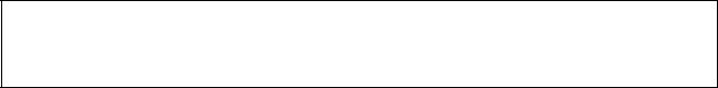
The following diagram shows the contents of a project. The function block definitions are created at the same directory level as the program within the relevant PLC directory.
4
Introducing the Function Blocks |
Section 1-1 |
Project file (.cxp)
PLC1
PLC2
Global symbol table
I/O table
PLC Setup
PLC memory table
Program (with rung comments)
Local symbol table
Section 1 (with instances)
Section 2 (with instances)
END section (with instances)
Function block definitions
FunctionBlock1
FunctionBlock2
Instances created in program sections.
Each function block can be stored in a separate definition file (.cxf).
Function Block Library
Files (*.cxf)
Project Text Files
Containing Function
Blocks (*.cxt)
A function block definition created in a project with CX-Programmer Ver. 5.0 can be saved as a file (1 definition = 1 file), enabling definitions to be loaded into other programs and reused.
Data equivalent to that in project files created with CX-Programmer Ver. 5.0 (*.cxp) can be saved as CXT text files (*.cxt).
1-1-4 CX-Programmer Ver. 5.0 Function Block Menus
The following tables list CX-Programmer Ver. 5.0 menus related to function blocks. For details on all menus, refer to the CX-Programmer Ver. 5.0 Operation Manual (W437).
Main Menu
Main menu |
|
Submenu |
Shortcut |
Function |
|
|
|
|
|
File |
Func- |
Load Function |
--- |
Reads the saved function block library files (*.cxf). |
|
tion |
Block from File |
|
|
|
Block |
|
|
|
|
Save Function |
--- |
Saves the created function block definitions to a file ([function block |
|
|
|
|||
|
|
Block to File |
|
library file]*.cxf). |
|
|
|
|
|
Edit |
Update Function Block |
--- |
When a function block definition’s I/O variables have been changed |
|
|
|
|
|
after the instance was created, an error will be indicated by display- |
|
|
|
|
ing the instance’s left bus bar in red. This command updates the |
|
|
|
|
instance with the new information and clears the error. |
|
|
|
|
|
Insert |
Function Block Invocation |
F |
Creates an instance in the program (section) at the present cursor |
|
|
|
|
|
location. |
|
|
|
|
|
|
Function Block Parameter |
P |
When the cursor is located to the left of an input variable or the right |
|
|
|
|
|
of an output variable, sets the variable’s input or output parameter. |
|
|
|
|
|
PLC |
Func- |
Function Block |
--- |
Sets the range of addresses (function block instance areas) inter- |
|
tion |
Memory Allocation |
|
nally allocated to the selected instance’s variables. |
|
Block |
|
|
|
|
Function Block |
--- |
Checks the status of the addresses internally allocated to the |
|
|
Mem- |
|||
|
Memory Statistics |
|
selected instance’s variables. |
|
|
ory |
|
|
|
|
Function Block |
--- |
Checks the addresses internally allocated to each variable in the |
|
|
|
|||
|
|
Instance Address |
|
selected instance. |
|
|
|
|
|
|
|
Optimize Function |
--- |
Optimizes the allocation of addresses internally allocated to vari- |
|
|
Memory |
|
ables. |
|
|
|
|
|
5
Introducing the Function Blocks Section 1-1
Main Popup Menus
Popup Menu for Function Block Definitions
Popup menu |
Function |
||
|
|
|
|
Insert Function Block |
Ladder |
Creates a function block definition with a ladder programming language algo- |
|
|
|
|
rithm. |
|
|
|
|
|
|
Structured Text |
Creates a function block definition with an ST language algorithm. |
|
|
|
|
|
|
From file |
Reads a function block definition from a function block library file (*.cxf). |
|
|
|
|
Popup Menu for Inserted Function Blocks
Popup menu |
Function |
|
|
Open |
Displays the contents of the selected function block definition on the right side of the window. |
|
|
Save Function Block File |
Saves the selected function block definition in a file. |
|
|
Compile |
Compiles the selected function block definition. |
|
|
Popup Menu for Function Block Variable Tables
Popup menu |
Function |
|
|
|
|
Edit |
Edits the variable. |
|
|
|
|
Insert Variable |
Adds a variable to the last line. |
|
|
|
|
Insert Variable |
Above |
Inserts the variable above the current cursor position. |
|
|
|
|
Below |
Inserts the variable below the current cursor position. |
|
|
|
Cut |
Cuts the variable. |
|
|
|
|
Copy |
Copies the variable. |
|
|
|
|
Paste |
Pastes the variable. |
|
|
|
|
Find |
Searches for the variable. Variable names, variable comments, or all (text strings) can |
|
|
|
be searched. |
|
|
|
Replace |
Replaces the variable. |
|
|
|
|
Delete |
Deletes the variable. |
|
|
|
|
Rename |
Changes only the name of the variable. |
|
|
|
|
Popup Menu for Instances
|
Popup menu |
Function |
|
|
|
Edit |
Changes the instance name. |
|
|
|
|
Update Invocation |
When a function block definition’s I/O variables have been changed after the instance |
|
|
|
was created, an error will be indicated by displaying the instance’s left bus bar in red. |
|
|
This command updates the instance with the new information and clears the error. |
|
|
|
Go To |
Function Block Definition |
Displays the selected instance’s function block definition on the right side of the window. |
|
|
|
Shortcut Keys
F Key: Pasting Function
Block Definitions in
Program
P Key: Inputting
Parameters
Move the cursor to the position at which to create the copied function block instance in the Ladder Section Window, and click the F Key. This operation is the same as selecting Insert - Function Block Invocation.
Position the cursor at the left of the input variable, or at the right of the output variable and click the P Key. This operation is the same as selecting Insert - Function Block Parameter.
6
Function Blocks |
Section 1-2 |
1-2 Function Blocks
1-2-1 Outline
A function block is a basic program element containing a standard processing function that has been defined in advance. Once the function block has been defined, the user just has to insert the function block in the program and set the I/O in order to use the function.
As a standard processing function, a function block does not contain actual addresses, but variables. The user sets addresses or constants in those variables. These address or constants are called parameters. The addresses used by the variables themselves are allocated automatically by the CX-Pro- grammer for each program.
With the CX-Programmer, a single function block can be saved as a single file and reused in other PLC programs, so standard processing functions can be made into libraries.
|
|
|
|
Program 2 |
|
|
|
|
|
|
|
|
Copy of function block A |
||
Function block A |
|
Program 1 |
|
|
|
|
|
Standard |
|
|
Copy of function block A |
Variable |
Output |
||
|
|
|
|
||||
|
|
|
|
|
|
|
|
program section |
|
|
|
|
|
|
|
written with |
|
|
|
|
|
|
|
variables |
|
Input |
Variable |
Variable |
Output |
|
|
|
|
|
|
||||
Define in advance. |
|
|
|
|
|
|
|
Insert in |
|
Set |
|
|
Set |
|
|
program. |
|
|
|
|
|||
|
|
|
Copy of function block A |
|
|
||
Save function |
|
|
|
|
|
|
|
block as a file. |
|
|
|
|
|
|
|
Convert to |
|
Input |
Variable |
Variable |
Output |
|
|
library function. |
|
|
|
||||
|
|
|
|
|
|
|
|
Function |
|
|
|
|
|
|
|
block A |
To another PLC program |
|
|
|
|
||
Reuse. |
|
|
|
|
|||
|
|
|
|
|
|
|
|
1-2-2 Advantages of Function Blocks
Structured
Programming
Easy-to-read “Black Box”
Design
Use One Function Block for Multiple Processes
Function blocks allow complex programming units to be reused easily. Once standard programming is created in a function block and saved in a file, it can be reused just by placing the function block in a program and setting the parameters for the function block’s I/O. The ability to reuse existing function blocks will save significant time when creating/debugging programs, reduce coding errors, and make the program easier to understand.
Structured programs created with function blocks have better design quality and require less development time.
The I/O operands are displayed as variable names in the program, so the program is like a “black box” when entering or reading the program and no extra time is wasted trying to understand the internal algorithm.
Many different processes can be created easily from a single function block by using the parameters in the standard process as input variables (such as timer SVs, control constants, speed settings, and travel distances).
7
Function Blocks |
Section 1-2 |
Reduce Coding Errors |
Coding mistakes can be reduced because blocks that have already been |
|
debugged can be reused. |
Data Protection |
The variables in the function block cannot be accessed directly from the out- |
|
side, so the data can be protected. (Data cannot be changed unintentionally.) |
Improved Reusability with |
The function block’s I/O is entered as variables, so it isn’t necessary to change |
Variable Programming |
data addresses in a block when reusing it. |
Creating Libraries |
Processes that are independent and reusable (such as processes for individ- |
|
ual steps, machinery, equipment, or control systems) can be saved as func- |
|
tion block definitions and converted to library functions. |
|
The function blocks are created with variable names that are not tied to actual |
|
addresses, so new programs can be developed easily just by reading the def- |
|
initions from the file and placing them in a new program. |
Compatible with |
Mathematical expressions can be entered in structured text (ST) language. |
Multiple Languages |
|
1-2-3 Function Block Structure
Function Block
Definitions
Function blocks consist of function block definitions that are created in advance and function block instances that are inserted in the program.
Function block definitions are the programs contained in function blocks. Each function block definition contains the algorithm and variable definitions, as shown in the following diagram.
|
|
|
|
|
|
|
Example: CLOCK PULSE |
|||
Function Block Definition |
||||||||||
|
1. Algorithm |
|||||||||
Example: CLOCK PULSE |
|
|||||||||
|
|
|
|
|
tim_b |
|
|
|||
|
Algorithm |
|
|
|
|
|
|
TIMX tim_a OFF_TIME |
|
|
|
|
|
|
tim_a |
|
|
||||
|
|
|
|
|
|
|
||||
|
|
|
|
|
|
|
||||
|
Variable definitions |
|
|
|
TIMX tim_b ON_TIME |
|
||||
|
|
|
|
|
|
|
|
|||
|
|
|
|
|
|
|
|
|
||
|
|
|
|
|
|
|
|
ENO |
||
|
|
|
||||||||
|
|
|
|
|
|
|
|
|
|
|
2. Variable Definitions
Usage |
Name |
Type |
Internal |
tim_a |
TIMER |
Internal |
tim_b |
TIMER |
Input |
ON_TIME |
INT |
Input |
OFF_TIME |
INT |
1. Algorithm
Standardized programming is written with variable names rather than real I/O memory addresses. In the CX-Programmer, algorithms can be written in either ladder programming or structured text.
8
Function Blocks |
Section 1-2 |
Number of Function Block
Definitions
Instances
2. Variable Definitions
The variable table lists each variable’s usage (input, output, or internal) and properties (data type, etc.). For details, refer to 1-3 Variables.
The maximum number of function block definitions that can be created for one CPU Unit is either 128 or 1,024 depending on the CPU Unit model.
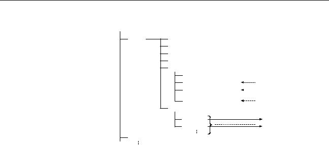
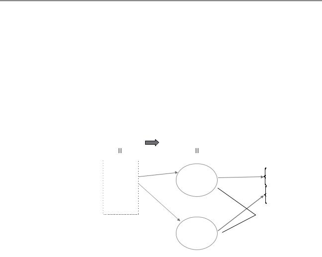
To use an actual function block definition in a program, create a copy of the function block diagram and insert it in the program. Each function block definition that is inserted in the program is called an “instance” or “function block instance.” Each instance is assigned an identifier called an “instance name.”
By generating instances, a single function block definition can be used to process different I/O data with the same function.
|
Not yet in program |
|
|
|
|
|
|
|
|
|
|
|
|
|
|
|
|
|
|
|
and memory not yet |
|
|
|
Block instance in program with memory |
|
|
|
|
|
|
|
|||||||
|
allocated |
|
|
|
|
allocated. (object) |
|
|
|
|
|
|
|
|
|
|
|||
|
(abstract). |
|
|
|
|
|
|
|
|
|
|
|
|
|
|
|
|
|
|
Function Block Definition FB1 |
Program |
Instance |
|
|
|
|
|
|
|
|
Memory |
||||||||
|
|
|
|
|
|
|
|
|
|
|
|
|
|
|
|
|
|
||
|
1. Algorithm |
Insert in |
|
Instance FB1 |
_1 of function block definition FB1 |
|
|
|
|
|
used |
||||||||
|
|
|
|
|
|
|
|
|
|
|
|
|
|
|
|
|
|||
|
Standard |
|
program. |
|
|
|
|
|
|
|
|
|
|
Automatic |
|
|
|
||
|
|
|
|
|
|
|
|
|
|
|
|
allocation |
|
Memory |
|
||||
|
program unit |
|
|
|
|
|
|
|
|
|
|
|
|
|
|
||||
|
with variable |
|
|
|
|
|
Input |
|
a |
b |
|
Output data |
|
|
|
|
|
for FB1_1 |
|
|
names a, b, c, |
|
|
|
|
|
data |
|
|
|
|
|
|
|
|
|
|
|
|
|
|
|
|
|
|
|
|
|
|
|
|
|
|
|
|
|
|||
|
etc. |
|
|
|
|
|
|
|
|
c |
|
Output data |
|
Automatic |
|
Memory |
|
||
|
|
|
|
|
|
|
|
|
|
|
|
|
|
||||||
|
|
|
|
|
|
|
|
|
|
|
|
|
|
|
|||||
|
2. Parameters |
|
|
|
|
|
|
|
|
|
|
|
|||||||
|
Insert in |
|
|
|
|
|
|
|
|
|
|
allocation |
|
|
for FB1_2 |
||||
|
|
|
|
|
|
|
|
|
|
|
|||||||||
|
Table defining usage |
|
|
|
|
|
|
|
|
|
|
|
|
|
|
|
|
|
|
|
and properties of |
|
program. |
|
|
|
|
|
|
|
|
|
|
|
|||||
|
variables a, b, c, etc. |
|
|
|
|
|
|
|
|
|
|
|
|
|
|
|
|
|
|
|
|
|
|
|
Instance FB1_2 of function block definition FB1 |
|
Different I/O data |
||||||||||||
|
|
|
|
|
|
|
|
|
|
|
|
|
|
|
|
can be processed |
|||
|
|
|
|
|
|
|
|
|
|
|
|
|
|
|
|
with the same |
|||
|
|
|
|
|
|
|
|
|
|
|
|
|
|
|
|
||||
|
|
|
|
|
|
|
|
|
|
|
|
|
|
|
|
||||
|
|
|
|
|
|
|
Input |
|
a |
b |
|
Output data |
|
|
|
function. |
|||
|
|
|
|
|
|
|
|
|
|
|
|
|
|
|
|||||
|
|
|
|
|
|
|
data |
|
|
|
|
|
|
|
|
|
|
||
|
|
|
|
|
|
|
|
|
|
|
|
|
|
|
|
|
|
||
|
|
|
|
|
|
|
|
|
|
c |
|
Output data |
|
|
|
|
|
|
|
|
|
|
|
|
|
|
|
|
|
|
|
|
|
|
|
|
|
|
|
|
|
|
|
|
|
|
|
|
|
|
|
|
|
|
|
|
|
|
|
|
|
|
|
|
|
|
|
|
|
|
|
|
|
|
|
|
|
|
|
Note Instances are managed by names. More than one instance with the same name can also be inserted in the program. If two or more instances have the same name, they will use the same internal variables. Instances with different names will have different internal variables.
For example, consider multiple function blocks that use a timer as an internal variable. In this case all instances will have to be given different names. If more than one instance uses the same name, the same timer would be used in multiple locations, resulting in duplicated use of the timer.
If, however, internal variables are not used or they are used only temporarily and initialized the next time an instance is executed, the same instance name can be used to save memory.
9
Function Blocks |
Section 1-2 |
instance_A
TIMER_FB
Function Block Definition
TIMER_FB
Variable Definitions |
|
Internal variable: WORK_NUM |
Use same internal variables. |
|
instance_A
TIMER_FB
Use different internal variables.
instance_B TIMER_FB
Number of Instances |
Multiple instances can be created from a single function block definition. Up to |
||||||||
|
either 256 or 2,048 instances can be created for a single CPU Unit depending |
||||||||
|
on the CPU Unit model. The allowed number of instances is not related to the |
||||||||
|
number of function block definitions and the number of tasks in which the |
||||||||
|
instances are inserted. |
|
|
|
|||||
Parameters |
Each time an instance is created, set the real I/O memory addresses or con- |
||||||||
|
stants for I/O variables used to pass input data values to instances and obtain |
||||||||
|
output data values from instances. These addresses and constants are called |
||||||||
|
parameters. |
|
|
|
|
||||
|
|
|
|
|
|
|
|||
|
|
|
|
|
Instance of Function Block Definition A |
||||
|
|
|
|
|
|
|
|
|
|
|
|
|
|
|
|
|
|
|
|
|
|
|
|
|
|
|
|
|
|
|
|
|
|
|
|
|
|
|
|
|
|
|
|
Input 0.00 |
a |
b |
Output 2.00 |
||
|
|
|
|
Input 3.00 |
c |
|
|
|
|
|
|
|
|
|
|
|
|
|
|
Set the constants or input source addresses from which to pass data.
Set the constant or output destination address to which to pass data.
Here, it is not the input source address itself, but the contents at the input address in the form and size specified by the variable data type that is passed to the function block. In a similar fashion, it is not the output destination address itself, but the contents for the output address in the form and size specified by the variable data type that is passed from the function block.
10
Function Blocks |
Section 1-2 |
Even if an input source address (i.e., an input parameter) or an output destination address (i.e., an output parameter) is a word address, the data that is passed will be the data in the form and size specified by the variable data type starting from the specified word address.
Program
Instance of Function Block Definition A
Input D100 |
m |
k |
Output D300 |
Input D200 |
n |
|
|
Examples:
If m is type WORD, one word of data from D100 will be passed to the variable.
If n is type DWORD, two words of data from D200 and D201 will be passed to the variable.
If k is type LWORD, four words of data from the variable will be passed to the D300 to D303.
Note (1) Only addresses in the following areas can be used as parameters: CIO Area, Auxiliary Area, DM Area, EM Area (banks 0 to C), Holding Area, and Work Area.
The following cannot be used: Index and Data Registers (both direct and indirect specifications) and indirect addresses to the DM Area and EM Area (both in binary and BCD mode).
(2)Local and global symbols in the user program can also be specified as parameters. To do so, however, the data size of the local or global symbol must be the same as the data size of the function block variable.
(3)When an instance is executed, input values are passed from parameters to input variables before the algorithm is processed. Output values are passed from output variables to parameters just after processing the algorithm. If it is necessary to read or write a value within the execution cycle of the algorithm, do not pass the value to or from a parameter. Assign the value to an internal variable and use an AT setting (specified addresses).
!Caution If an address is specified in an input parameter, the values in the address are passed to the input variable. The actual address data itself cannot be passed.
!Caution Parameters cannot be used to read or write values within the execution cycle of the algorithm. Use an internal variable with an AT setting (specified addresses). Alternatively, reference a global symbol as an external variable.
■ Reference Information
A variety of processes can be created easily from a single function block by using parameter-like elements (such as fixed values) as input variables and changing the values passed to the input variables for each instance.
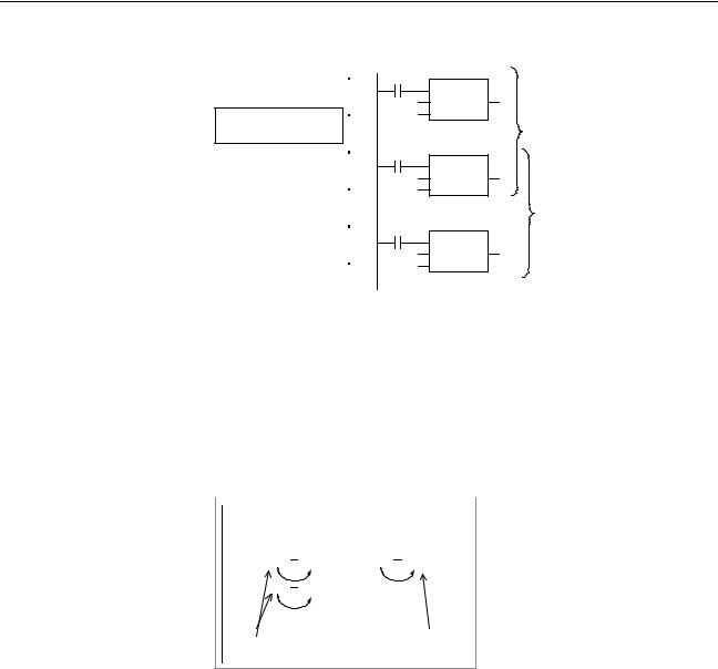
Example: Creating 3 Instances from 1 Function Block Definition
11

Function Blocks |
Section 1-2 |
Function Block Definition
Example: CONTROL
Algorithm
Variables
Example: There are 3 FB
instances and each has its own I/O and internal variables.
|
|
Cyclic task 0 |
|
||||||
Instance |
|
|
|
|
|
CASCADE_01 |
|
||
CASCADE_01 |
|
P_On |
|
CONTROL |
1.0 |
||||
|
Algorithm |
|
|
|
|
|
EN |
ENO |
|
|
&20 |
|
|||||||
|
Internal and I/O |
|
&10 |
ON_TIME |
|
||||
|
|
|
|
|
|||||
|
variables |
|
OFF_TIME |
|
|||||
|
|
|
|
|
|
|
|
|
|
|
|
|
|
|
|
|
|
|
|
|
|
|
|
|
|
|
|
||
Instance |
|
|
|
|
|
CASCADE_02 |
1.1 |
||
CASCADE_02 |
|
P_On |
|
CONTROL |
|||||
|
Algorithm |
|
|
|
|
|
EN |
ENO |
|
|
&15 |
|
|||||||
|
Internal and I/O |
|
|
|
|
|
ON_TIME |
|
|
|
|
|
|
|
|
|
|
|
|
|
variables |
|
&10 |
OFF_TIME |
|
||||
|
|
|
|
|
|
|
|
|
|
|
|
|
|
|
|
|
|
|
|
|
|
Cyclic task 1 |
|
|||||
Instance |
|
|
|
|
|
CASCADE_03 |
|
|
CASCADE_03 |
|
P_On |
CONTROL |
1.2 |
||||
|
Algorithm |
|
|
|
|
|
EN ENO |
|
|
&7 |
|
|
|||||
|
Internal and I/O |
|
|
|
|
|
ON_TIME |
|
|
|
|
|
|
|
|
|
|
|
variables |
|
&8 |
|
OFF_TIME |
|
||
|
|
|
|
|
|
|
|
|
|
|
|
|
|
|
|
|
|
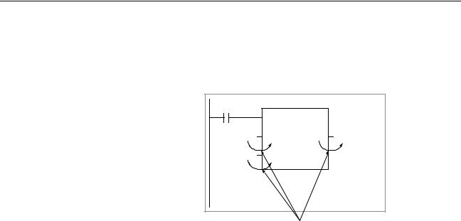
If internal variables are not used, if processing will not be affected, or if the internal variables are used in other locations, the same instance name can be used at multiple locations in the program.
Function block definition
Example: CONTROL
Algorithm
Variables
The same instance can be used at multiple locations.
Instance
CASCADE
Algorithm
Internal and I/O variables
Cyclic task 0
CASCADE
|
P_On |
CONTROL |
1.0 |
||||
|
|
||||||
|
|
|
|
|
EN |
ENO |
|
&100 |
PARA_1 |
|
|||||
|
|
|
|
|
|
||
&130 |
PARA_2 |
|
|||||
|
|
|
|
|
|
|
|
|
|
|
|
|
|
|
|
|
P_On |
CASCADE |
1.1 |
||||
|
CONTROL |
|
|||||
|
|
|
|
|
EN |
ENO |
|
|
&50 |
PARA_1 |
|
||||
|
|
|
|
|
|
||
|
&150 |
PARA_2 |
|
||||
|
|
|
|
|
|
|
|
|
|
|
|
|
|
|
|
|
|
|
|
|
|
|
|
Cyclic task 1
CASCADE
P_On |
CONTROL |
1.2 |
|
&100 |
EN |
ENO |
|
PARA_1 |
|
||
|
|
||
&200 |
PARA_2 |
|
|
Some precautions are required when using the same memory area. For example, if the same instance containing a timer instruction is used in more than one program location, the same timer number will be used causing coil duplication, and the timer will not function properly if both instructions are executed.
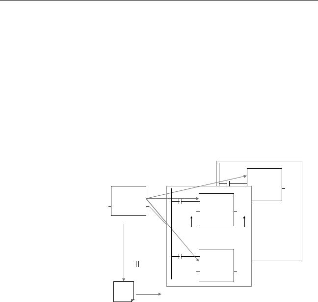
Registration of Instances Each instance name is registered in the global symbol table as a file name.
Program
Instance (sample) of function block definition A
ab
c
The instance is registered in the global symbol table with the instance name as the symbol name.
Name |
|
Data type |
Address/ |
|
|||
|
value |
|
|||||
|
|
|
|
|
|
|
|
sample |
FB [FunctionBlock1] |
N/A[Auto] |
|
||||
|
|
|
|
|
The function block definition |
||
|
|
|
|
|
|||
|
|
|
|
|
name is registered after FB in |
||
Instance name |
|
|
square parentheses [ ]. |
||||
12
Variables |
Section 1-3 |
1-3 Variables
1-3-1 Introduction
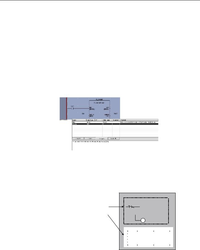
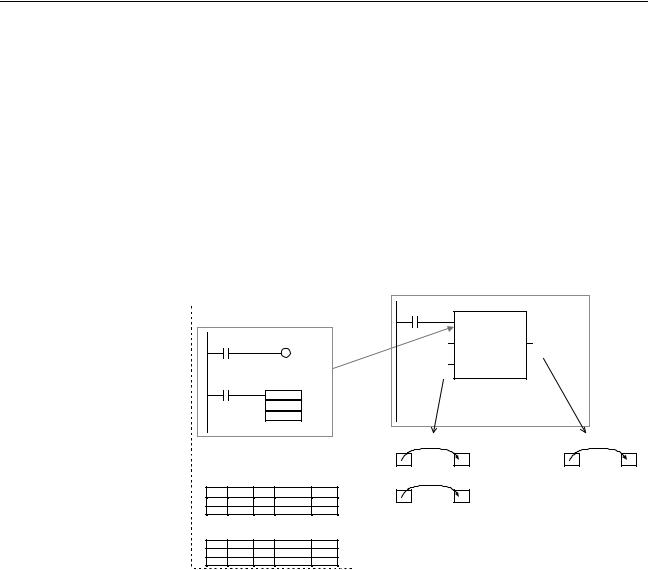
In a function block, the addresses (see note) are not entered as real I/O memory addresses, they are all entered as variable names. Each time an instance is created, the actual addresses used by the variable are allocated automatically in the specified I/O memory areas by the CX-Programmer. Consequently, it isn’t necessary for the user to know the real I/O memory addresses used in the function block, just as it isn’t necessary to know the actual memory allocations in a computer. A function block differs from a subroutine in this respect, i.e., the function block uses variables and the addresses are like “black boxes.”
Example: |
|
|
|
|
|
|
|
|
|
|
|
|
|
|
|
Program |
|
|
|
|
|
|
|
Function block definition A |
|
Instance of function block definition A |
|
|
|
||||||
Standard program section with |
|
|
|
|
|||||||
|
|
|
|
|
|
|
|
||||
variable names a, b, c, etc. |
|
|
|
|
|
|
|
|
|||
|
|
|
|
Insert in |
|
|
|
|
|
|
|
a |
|
|
b |
program. |
Input 0.00 |
a |
b |
Output 2.00 |
|
|
|
|
|
|
|
|
Input 3.00 |
c |
|
|
|
|
|
c |
|
|
|
Specify inputs and outputs |
|
|
|
|
|
|
|
|
|
|
MOV |
at the same time. |
|
|
|
|
|
|
|
|
|
|
|
|
|
|
|
|
|
|
|
|
|
|
|
Status of 0.00 (1 or 0) is |
|
Status of b (1 or 0) is |
|
||||
Table indicating usage and |
passed to a. |
|
|
passed to 2.00. |
|
||||||
prpperties of variables a, b, c, etc. |
0.00 1 |
a |
1 |
|
b |
1 |
2.00 |
1 |
|||
Usage: Inputs |
|
|
|||||||||
|
Status of 3.00 (1 or 0) is |
|
|
|
|
|
|||||
|
Prpperties: |
|
|
|
|
|
|
||||
|
|
passed to c. |
|
|
|
|
|
|
|||
Name |
Type |
AT |
Initial Value Retained |
3.00 0 |
c |
0 |
|
|
|
|
|
a |
BOOL |
|
|
|
|
|
|
|
|||
|
|
|
|
|
|
|
|
|
|
||
c |
BOOL |
|
|
|
|
|
|
|
|
|
|
Usage: Outputs |
|
|
The system automatically allocates the |
|
|
||||||
|
Prpperties: |
|
|
addresses used by variables a, b, and c. For |
|
||||||
Name Type |
AT |
Initial Value Retained |
|
example, when W100 to W120 is set as the |
|
||||||
b |
BOOL |
|
|
|
|
||||||
|
|
|
system’s non-retained memory area, bit |
|
|
||||||
|
|
|
|
|
|
|
|||||
|
|
|
|
|
addresses such as a = W10000, b = W10001, |
||||||
|
|
|
|
|
and c = W10002 will be allocated. |
|
|
||||
Note Constants are not registered as variables. Enter constants directly in instruction operands.
•Ladder programming language: Enter hexadecimal numerical values after the # and decimal values after the &.
•Structured text (ST language): Enter hexadecimal numerical values after 16# and enter decimal numerical values as is.
Exception: Enter directly or indirectly specified addresses for Index Registers IR0 to IR15 and Data Registers DR0 to DR15 directly into the instruction operand.
1-3-2 Variable Usage and Properties
Variable Usage |
The following variable types (usages) are supported. |
|
|
Internals: |
Internal variables are used only within an instance. They cannot |
|
|
be used pass data directly to or from I/O parameters. |
|
Inputs: |
Input variables can input data from input parameters outside of |
|
|
the instance. The default input variable is an EN (Enable) vari- |
|
|
able, which passes input condition data. |
13

Variables |
Section 1-3 |
Outputs: Output variables can output data to output parameters outside of the instance. The default output variable is an ENO (Enable Out) variable, which passes the instance’s execution status.
Externals: External variables are either system-defined variables registered in advance with the CX-Programmer, such as the Condition Flags and some Auxiliary Area bits, or user-defined global symbols for use within instances.
For details on variable usage, refer to the section on Variable Type (Usage) under Variable Definitions in 2-1-2 Function Block Elements.
The following table shows the number of variables that can be used and the kind of variable that is created by default for each of the variable usages.
1-3-3 Variable Properties
|
Variables have the following properties. |
Variable Name |
The variable name is used to identify the variable in the function block. It |
|
doesn’t matter if the same name is used in other function blocks. |
Note |
The variable name can be up to 30,000 characters long, but must not begin |
|
with a number. Also, the name cannot contain two underscore characters in a |
|
row. The character string cannot be the same as that of a an index register |
|
such as in IR0 to IR15. For details on other restrictions, refer to Variable Defi- |
|
nitions in 2-1-2 Function Block Elements. |
Data Type |
Select one of the following data types for the variable: |
|
BOOL, INT, UINT, DINT, UDINT, LINT, ULINT, WORD, DWORD, LWORD, |
|
REAL, LREAL, TIMER, COUNTER |
|
For details on variable data types, refer to Variable Definitions in 2-1-2 Func- |
|
tion Block Elements. |
AT Settings (Allocation to |
It is possible to set a variable to a particular I/O memory address rather than |
an Actual Addresses) |
having it allocated automatically by the system. To specify a particular |
|
address, the user can input the desired I/O memory address in this property. |
|
This property can be set for internal variables only. Even if a specific address |
|
is set, the variable name must still be used in the algorithm. |
|
Refer to Variable Definitions in 2-1-2 Function Block Elements for details on |
|
AT settings and 2-4-3 AT Settings for Internal Variables for details on using AT |
|
settings. |
Array Settings |
A variable can be treated as a single array of data with the same properties. |
|
To convert a variable to an array, specify that it is an array and specify the |
|
maximum number of elements. |
|
This property can be set for internal variables only. Only one-dimensional |
|
arrays are supported by the CX-Programmer Ver. 5.0. |
|
• Setting Procedure |
|
Click the Advanced Button, select the Array Variable option, and input the |
|
maximum number of elements. |
|
• When entering an array variable name in the algorithm in a function block |
|
definition, enter the array index number in square brackets after the vari- |
|
able number. |
|
For details on array settings, refer to Variable Definitions in 2-1-2 Function Block |
|
Elements. |
Initial Value |
This is the initial value set in a variable before the instance is executed for the |
|
first time. Afterwards, the value may be changed as the instance is executed. |
14
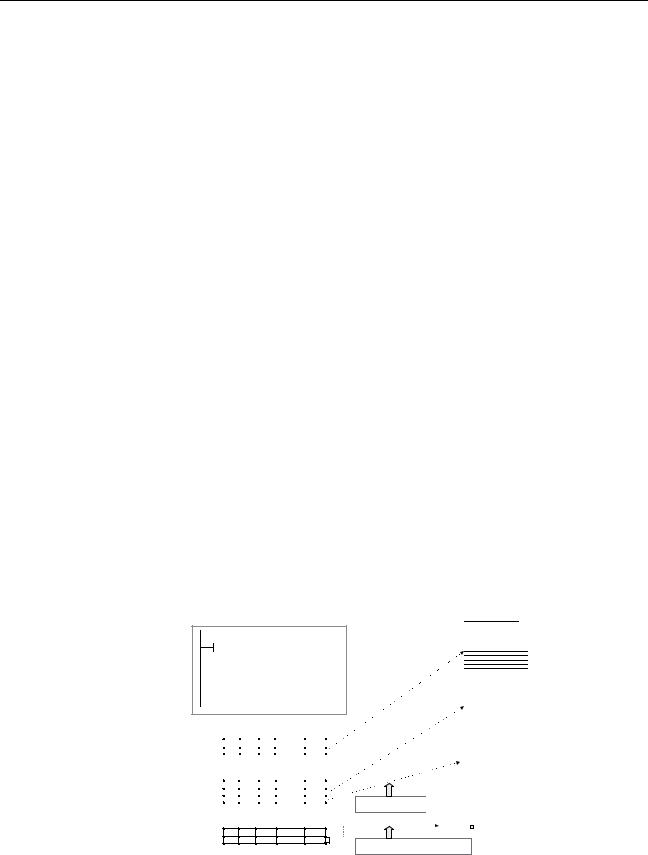
|
Variables |
Section 1-3 |
|
|
For example, set a boolean (BOOL) variable (bit) to either 1 (TRUE) or 0 |
|
|
(FALSE). Set a WORD variable to a value between 0 and 65,535 (between |
|
|
0000 and FFFF hex). |
|
|
If an initial value is not set, the variable will be set to 0. For example, a bool- |
|
|
ean variable would be 0 (FALSE) and a WORD variable would be 0000 hex. |
Retain |
Select the Retain Option if you want a variable’s data to be retained when the |
|
|
|
PLC is turned ON again and when the PLC starts operating. |
|
|
• Setting Procedure |
|
|
Select the Retain Option. |
1-3-4 Variable Properties and Variable Usage
The following table shows which properties must be set, can be set, and cannot be set, based on the variable usage.
Property |
|
Variable usage |
|
|
|
|
|
|
Internals |
Inputs |
Outputs |
|
|
|
|
Name |
Must be set. |
Must be set. |
Must be set. |
|
|
|
|
Data Type |
Must be set. |
Must be set. |
Must be set. |
|
|
|
|
AT (specified address) |
Can be set. |
Cannot be set. |
Cannot be set. |
|
|
|
|
Initial Value |
Can be set. |
Can be set. |
Can be set. |
|
|
(See note.) |
|
|
|
|
|
Retained |
Can be set. |
Can be set. |
Can be set. |
|
|
(See note.) |
|
|
|
|
|
Note Inputs can be set as initial values, but the value of the actual input parameter will be given priority.
1-3-5 Internal Allocation of Variable Addresses
When an instance is created from a function block definition, the CX-Program- mer internally allocates addresses to the variables. Addresses are allocated to all of the variables registered in the function block definition except for variables that have been assigned actual addresses with the AT Settings property.
Program
Instance of function block definition A
|
|
a |
b |
Output 2.00 |
|
|
|||
Input 0.00 |
||||
|
|
|
t |
Output 5.00 |
|
|
|
|
|
Note: Variable c is an internal variable, so it is not displayed.
Usage: Inputs
Properties:
Name |
Type |
AT |
Initial Value |
Retained |
|
a |
BOOL |
|
|
|
|
Usage: Outputs
Properties:
Name |
Type |
AT |
Initial Value |
Retained |
|
b |
BOOL |
|
|
YES |
|
t |
TIMER |
|
|
|
|
Usage: Internals
Properties:
Name Type AT InitialValue Retained
c BOOL 2000.00
FB instance areas
Non-retained area |
|
|
|
|
|
|
Starting address 15 |
0 |
|||||
|
|
|
CIO, H, W, |
|
|
Size (words) |
|
|
|
D, or E Area |
|
|
|
|
|
|
|
|
|
|
Retained area |
|
|
|
|
|
|
|
|
|
|
|
||
Starting address |
15 |
|
0 |
|||
|
|
|
|
|
|
|
|
|
|
H, D, or E |
|
|
Size (words) |
Timer area |
|
Area |
|
|
||
|
|
|
|
|||
|
|
|
|
|
||
|
|
|
|
|
||
Starting address |
|
|
|
|
Size (Completion |
|
|
T Area |
|
||||
|
|
|
|
|
Flags) |
|
Counter area |
|
|
|
|
|
|
|
Starting |
|
|
|
|
Size (Completion |
Automatic allocation of |
|
C Area |
|
|||
address |
|
|
|
Flags) |
||
addresses by system |
|
|
|
|
|
|
|
Example |
|
|
|
||
|
2000.00 |
|
|
|
|
|
Manual allocation of address to variable in FB by AT Settings option.
Setting Internal Allocation The user sets the function block instance areas in which addresses are allo- Areas for Variables cated internally by the system. The variables are allocated automatically by
the system to the appropriate instance area set by the user.
15
Loading...