


Modules described in this manual
IX2-RFAEVA-2 FV5-LAAR IX2-COMB FV5-FUR
INSTRUCTIONS
TOTAL INTERNAL
REFLECTION
ILLUMINATION SYSTEM
This instruction manual is for the Olympus Total Internal Reflection Illumination System. To ensure the safety, obtain optimum performance and to familiarize yourself fully with the use of this system, we recommend that you study this manual thoroughly before operating the system.
This system employs a laser light source. Take special care for safety and please also read the instruction manual for the laser light source.
Retain this instruction manual in an easily accessible place near the work desk for future reference.
A X 7 3 8 5

This device complies with the requirements of directive 98/79/EC concerning in vitro diagnostic medical devices. CE marking means the conformity to the directive.
NOTE: This equipment has been tested and found to comply with the limits for a Class A digital device, pursuant to Part 15 of the FCC Rules. These limits are designed to provide reasonable protection against harmful interference when the equipment is operated in a commercial environment. This equipment generates, uses, and can radiate radio frequency energy and, if not installed and used in accordance with the instruction manual, may cause harmful interference to radio communications. Operation of this equipment in a residential area is likely to cause harmful interference in which case the user will be required to correct the interference at his own expense.
FCC WARNING: Changes or modifications not expressly approved by the party responsible for compliance could void the user’s authority to operate the equipment.

IX2-RFAEVA-2
CONTENTS
CAUTION |
This system employs a laser light source and should be assembled and adjusted by qualified |
|
service personnel from Olympus. |
Never attempt to assemble or adjust the system for it is extremely hazardous.
IMPORTANT – Be sure to read this section for safe use of the equipment. – |
1-7 |
||
|
|
|
|
|
|
|
|
1 |
MODULE NOMENCLATURE |
8 |
|
|
|
|
|
2 |
CONTROLS |
9, 10 |
|
|
|
|
|
3 |
TOTAL INTERNAL REFLECTION FLUORESCENCE OBSERVATION |
11-14 |
|
|
3-1 |
Conditions of Observation...................................................................................................................................................... |
11 |
|
3-2 |
Preparation for Observation ................................................................................................................................................ |
12 |
|
|
1 Preparing for Laser Beam Introduction 2 Introducing the Laser Beam |
|
|
3-3 |
Observation Procedure .............................................................................................................................................................. |
13 |
|
|
1 Adjusting the Focus 2 Adjusting the Laser Beam Incidence Angle |
|
4 REFLECTED LIGHT FLUORESCENCE OBSERVATION
5USING THE CONTROLS
15
15, 16
1 |
Using the Binocular Tube Shutter |
2 Using the Specimen Cover |
3 |
Field Iris Aperture Diaphram |
4 Filter Slider |
6 TROUBLESHOOTING GUIDE
7SPECIFICATIONS
17
18
|
.............................................................PROPER SELECTION OF THE POWER SUPPLY CORD |
19, 20 |

IMPORTANT
This system has been designed to be used in combination with an IX2 series (IX81/IX71/IX51) or IX series (IX70/IX50) microscope to provide it with total internal reflection fluorescence illumination* using a laser light source.
*Total internal reflection fluorescence illumination utilizes the “evanescent light”, a very small amount of light at the sub-micrometric order penetrating beyond the total reflection of the cover glass (on the specimen side), to excite only the fluorescent molecules exiting near the cover glass surface. By eliminating the background fluorescence, it enables fluorescence observation with very high contrast.
LASER SAFETY PRECAUTIONS
1. The laser used in combination with this system is designated as a laser product of the following class.
CLASS IIIb (CDRH)
CLASS 3B (IEC60825-1)
 A CLASS 3B laser product is permitted to be used exclusively under control of a laser safety manager. Before using this product, read “USER’S SAFETY PROTECTION MEASURES ACCORDING TO IEC60825-1 ‘LASER PRODUCT RADIATION SAFETY STANDARD’” carefully to apply sufficient safety measures before use.
If there is any question concerning the laser product, please consult Olympus.
2.The laser beam output from the objective position or objective top lens may injure the skin exposed to it. Avoid exposing your finger or hand to the laser beam. Also, do not output the laser beam externally by engaging a mirror in the light path, for this is extremely hazardous if the output beam enters your eye.
3.Place the specimen horizontally on the stage. If the specimen is tilted, the laser beam may be reflected around the microscope and cause a hazard.
4.Never remove a unit while the laser beam output, for this may cause the laser beam to be output from there. Removal of any unit should be performed by Olympus qualified service personnel. When removal is required, please consult Olympus.
5.Be sure to cap the revolving nosepiece positions where no objective is attached.
6.Do not bend or pull excessively or step on the laser fiber cable, for this may damage the laser fiber cable and cause laser beam leakage that is extremely hazardous. Should laser beam leakage occur, immediately turn off the laser light source and contact Olympus.
7.The laser-cooling fans output warm winds through the air outlets. Do not place an object that is flammable or nonresistant to heat near an air outlet.
 To prevent electric shock or fire hazard, be sure to consult Olympus if you want to use a remote interlock connector.
1
IX2-RFAEVA-2
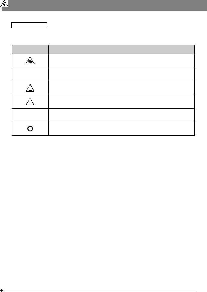
Safety Symbols
The following symbols are found on the system. Study the meaning of the symbols and always use the equipment in the safest possible manner.
Symbol
lIndicates that the main switch is ON.
2
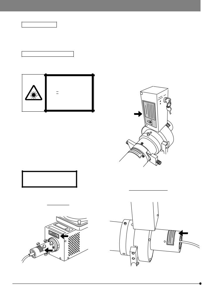
Warning Labels
Warning labels are placed at parts where special precaution is required when handling and using the system. Always heed the warnings.
If warning labels become soiled, peel off, etc., contact your local Olympus representative to have them replaced.
Warning Label Positions
}Warning labels are attached to the positions indicated by the arrows.
Fiber light illuminator
LASER LIGHT
AVOID EXPOSURE TO BEAM
CLASS IIIb LASER PRODUCT (CDRH)
CLASS 3B LASER PRODUCT (IEC60825-1 :1993+A1 :1997+A2 :2001)
50mW MAX CW 400-700nm
CAUTION-CLASS 3B
LASER RADIATION WHEN OPEN.
AVOID EXPOSURE TO THE BEAM.
Fiber light illuminator
Ar laser unit
3

IX2-RFAEVA-2
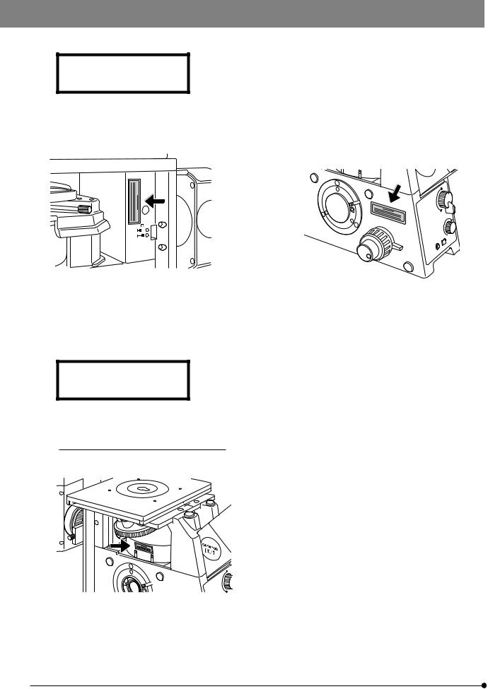
CAUTION-CLASS 3B
LASER RADIATION WHEN OPEN.
AVOID EXPOSURE TO THE BEAM.
Fiber light illuminator |
|
Straight light illuminator |
Binocular tube & binocular tube shutter |
Microscope frame & revolving nosepiece |
||||||||||||||||
|
|
|
|
|
|
|
|
|
|
|
|
|
|
|
|
|
|
|
|
|
|
|
|
|
|
|
|
|
|
|
|
|
|
|
|
|
|
|
|
|
|
|
|
|
|
|
|
|
|
|
|
|
|
|
|
|
|
|
|
|
|
|
|
|
|
|
|
|
|
|
|
Laser combiner IX2-COMB
4
CAUTION-CLASS 3B
LASER RADIATION WHEN OPEN.
AVOID EXPOSURE TO THE BEAM.
Microscope frame (rear right) |
|
Microscope frame (left side port) |
AVOID EXPOSURE
LASER RADIATION IS EMITTED
FROM THIS APERTURE.
Microscope left side (Reflected illumination and observation light path)
5
 Loading...