


 Loading...
INSTRUCTIONS
INDUSTRIAL VIDEOSCOPE
IPLEX MX II series

Contents |
|
Warning and Rating Plates............................................ |
1 |
1. Rating plate A.......................................................................................... |
1 |
2. Rating plate B.......................................................................................... |
1 |
3. Warning plate .......................................................................................... |
2 |
Important Information – Please Read Before Use....... |
3 |
Intended use.............................................................................................. |
3 |
Instruction manual.................................................................................... |
3 |
Combined ancillary equipment................................................................ |
3 |
Repair and modification .......................................................................... |
3 |
Signal words.............................................................................................. |
4 |
Dangers, warnings and cautions............................................................. |
4 |
Handling of the battery............................................................................. |
7 |
Product configurations of the IPLEX MX II series.................................. |
9 |
Chapter 1 Checking the package contents ........... |
10 |
1.1 Checking the package contents................................................ |
10 |
IPLEX MX II series package contents....................................................... |
10 |
Chapter 2 Instrument nomenclature and |
|
functions ................................................. |
11 |
2.1 System nomenclature ................................................................ |
11 |
2.2 Main unit nomenclature and functions..................................... |
13 |
2.3 Control unit nomenclature and functions ................................ |
14 |
Chapter 3 Preparation and inspection |
|
before observation ................................. |
16 |
3.1 Transportation of the case......................................................... |
16 |
When using the handle ............................................................................. |
16 |
Taking the instrument out of the case ....................................................... |
17 |
i

3.2 |
Setting up the main unit............................................................. |
19 |
|
Using the handle ....................................................................................... |
21 |
3.3 |
Preparing the power supply ...................................................... |
22 |
|
Supplying power from the battery ............................................................. |
22 |
|
Supplying power from the AC adapter ...................................................... |
24 |
3.4 |
Inspecting the insertion tube..................................................... |
25 |
|
Inspecting the external appearance of the insertion tube ......................... |
25 |
|
Inspecting the insertion tube distal end..................................................... |
25 |
3.5Inspecting the side view mirror adapter (optional)
|
(for IV8630M) ............................................................................... |
27 |
|
|
Checking the side view mirror adapter and connection screws ................ |
27 |
|
|
Attaching and detaching the side view mirror adapter .............................. |
28 |
|
|
Inspecting the parts of the side view mirror adapter ................................. |
30 |
|
3.6 |
Inspecting the control unit and the universal cable................ |
31 |
|
3.7 |
Inspecting the LCD monitor....................................................... |
32 |
|
|
Inspecting the external appearance .......................................................... |
32 |
|
3.8 |
Mounting of the control unit on the main unit ......................... |
33 |
|
3.9 |
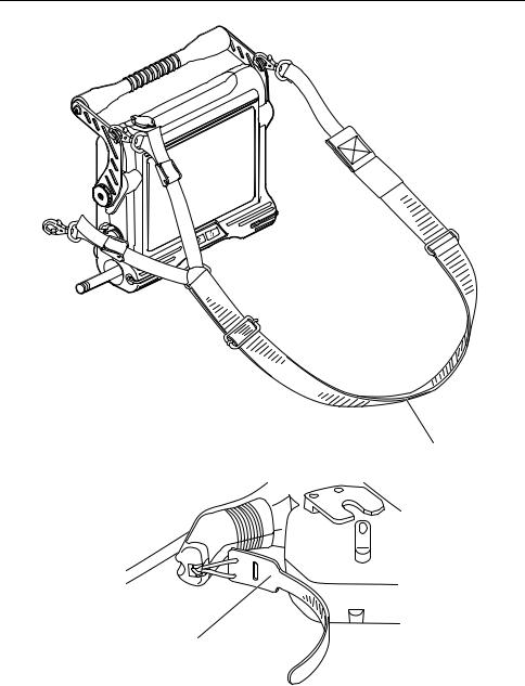
Attaching and detaching the strap............................................ |
36 |
|
|
Attaching the strap .................................................................................... |
36 |
|
|
Removing the strap ................................................................................... |
39 |
|
Chapter 4 |
Basic operations .................................... |
40 |
|
4.1 |
Turning on the power ................................................................. |
40 |
|
|
Turning the power on ................................................................................ |
40 |
|
|
Checking the LCD monitor image ............................................................. |
41 |
|
|
Indicator display ........................................................................................ |
41 |
|
|
Display language setting ........................................................................... |
41 |
|
|
Date and time settings .............................................................................. |
42 |
|
|
Checking the illumination lighting.............................................................. |
42 |
|
|
White balance adjustment......................................................................... |
42 |
|
|
Checking the angulation functions ............................................................ |
42 |
|
|
Checking the angulation lock .................................................................... |
43 |
|
ii

4.2 |
Inserting the insertion tube ....................................................... |
44 |
|
|
Holding the control unit and insertion tube................................................ |
44 |
|
|
Inserting the insertion tube........................................................................ |
45 |
|
|
Angulation operation ................................................................................. |
46 |
|
4.3 |
Withdrawing the insertion tube ................................................. |
47 |
|
|
Releasing the angulation lock ................................................................... |
47 |
|
|
Withdrawing the insertion tube.................................................................. |
47 |
|
4.4 |
Adjusting the image ................................................................... |
48 |
|
|
Still image (freeze) .................................................................................... |
48 |
|
|
Zoom ......................................................................................................... |
48 |
|
|
Adjusting the brightness............................................................................ |
49 |
|
|
Monochrome boost ................................................................................... |
49 |
|
4.5 |
Recording the image .................................................................. |
50 |
|
|
Image recording preparation ..................................................................... |
50 |
|
|
Recording a still image.............................................................................. |
52 |
|
4.6 |
Replaying the image................................................................... |
53 |
|
|
Quick replay of most recent image............................................................ |
53 |
|
|
Slide retrieval ............................................................................................ |
53 |
|
4.7 |
Displaying a live image on an external monitor ...................... |
54 |
|
Chapter 5 |
Menu operations and functions ............ |
55 |
|
5.1 |
Operating menu .......................................................................... |
55 |
|
|
Menu operations ....................................................................................... |
55 |
|
|
Example of operations .............................................................................. |
55 |
|
5.2 |
Using the live screen/frozen screen ......................................... |
57 |
|
|
Live screen/frozen screen menu display and functions ............................ |
57 |
|
|
Inputting the title........................................................................................ |
58 |
|
|
Setting the date and time .......................................................................... |
60 |
|
|
Language selection ................................................................................... |
62 |
|
5.3 |
Using the retrieve screen........................................................... |
63 |
|
|
Retrieve screen menu display and functions ............................................ |
63 |
|
|
Delete image ............................................................................................. |
63 |
|
iii

Chapter 6 Operations on a computer..................... |
65 |
||
6.1 |
Using recorded images on a computer .................................... |
65 |
|
|
Reading images with a computer.............................................................. |
65 |
|
Chapter 7 Storage and maintenance...................... |
66 |
||
7.1 |
Remaining battery power........................................................... |
66 |
|
7.2 |
Replacing the battery ................................................................. |
67 |
|
|
Replacing the battery ................................................................................ |
67 |
|
7.3 |
Cleaning....................................................................................... |
69 |
|
|
Cleaning the insertion tube ....................................................................... |
69 |
|
|
Cleaning the LCD monitor......................................................................... |
69 |
|
|
Cleaning the main unit and control unit..................................................... |
70 |
|
7.4 |
Repacking the case .................................................................... |
71 |
|
|
Locking the case ....................................................................................... |
73 |
|
7.5 |
Storage precautions ................................................................... |
74 |
|
Chapter 8 |
Troubleshooting ..................................... |
75 |
|
8.1 |
Troubleshooting guide............................................................... |
76 |
|
|
Error messages......................................................................................... |
76 |
|
|
General troubles during operation............................................................. |
78 |
|
8.2 |
Returning the instrument for repair .......................................... |
80 |
|
Chapter 9 |
Specifications ......................................... |
81 |
|
9.1 |
Operating environment .............................................................. |
81 |
|
9.2 |
Other specifications ................................................................... |
82 |
|
|
Carrying case specifications ..................................................................... |
86 |
|
|
Side view mirror adapter specifications..................................................... |
87 |
|
|
External application standard.................................................................... |
88 |
|
Appendix |
....................................................................... |
90 |
|
System chart............................................................................................ |
90 |
||
iv
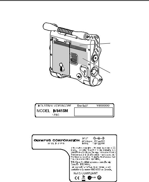
Warning and Rating Plates
Safety-related labels and symbols are attached to the instrument at the locations shown below.
If labels or symbols are missing or illegible, please contact Olympus.
1. Rating plate A
3. Warning plate 
2. Rating plate B
1. Rating plate A
2. Rating plate B
1
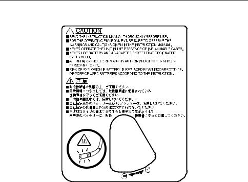
3. Warning plate
2

Important Information – Please Read
Before Use
Intended use
This instrument has been designed to be used with IPLEX MX II series and ancillary equipment for observation and examination of the insides of a machinery, equipment or building that cannot be observed directly from the outside.
Do not use this instrument for any purpose other than its intended use, particularly for observation or examination of the inside of a human or animal body cavity.
Instruction manual
This instruction manual contains essential information on using this instrument safely and effectively.
Before use, thoroughly review this manual and the manuals of all equipment which will be used during the procedure and use the equipment as instructed. Keep this and all related instruction manuals in a safe, accessible location.
If you have any questions about any information in this manual, please contact Olympus.
Combined ancillary equipment
Refer to the “System chart” page 90 in the Appendix to confirm that this instrument is compatible with the ancillary equipment being used.
Using incompatible equipment can result in malfunction and/or equipment damage.
 Repair and modification
This instrument does not contain any user serviceable parts. Do not disassemble, modify or attempt to repair. User injury and/or equipment damage can result.
3

Signal words
The following signal words are used throughout this manual.
DANGER
•Indicates an imminently hazardous situation which, if not avoided, will result in death or serious injury.
WARNING
•Indicates a potentially hazardous situation which, if not avoided, could result in death or serious injury.
CAUTION
•Indicates a potentially hazardous situation which, if not avoided, may result in minor or moderate injury. It may also be used to alert against unsafe practices or potential equipment damage.
NOTE
• Indicates additional helpful information.
Dangers, warnings and cautions
Follow the dangers, warnings and cautions described below when handling this instrument. The information is to be supplemented by the dangers, warnings and cautions given in each chapter.
DANGER
•Never use this instrument in observation inside the human and animal cavity. The human body or animal may be injured.
WARNING
•Never use this instrument in a flammable atmosphere. Otherwise, an explosion or fire may result.
•Do not use the instrument in an environment filled with fine particles such as metal dust.
•With the exception of the insertion tubes, this instrument and its case are not designed to be waterproof. Except for the insertion tube, never use or store the instrument in any location where it might be submerged in water. An electric shock may result.
•Never use this instrument on a piece of electrical equipment being energized. Since the exterior finish of the insertion tube is electroconductive, an electric shock may occur if it is brought in contact with an active part.
•Always turn the LIGHT button ( 
 ) OFF when the instrument is not in use. Otherwise the light emitted from the insertion tube may heat a nearby object and cause fire ignition.
•The distal end of the insertion tube may become hot due to the illumination light or the internal heating caused by electrical parts. Touching the distal end immediately after having turned off the light source may cause burn on your skin.
4
•Do not allow the light emitted from the insertion tube’s distal end to enter your eye directly. Otherwise, an eye injury may result.
•Should any abnormality be detected during angulation operation, do not continue the angulation operation by force. Otherwise, the insertion tube or examination target may be damaged.
•Do not subject the LCD surface to impact or strong pressure. Doing so could shatter the LCD screen and cause personal injury.
•Do not rub the LCD with hard or sharp objects. This can crack or scratch the LCD panel.
•Do not allow a metallic object or a fluid such as water enter the battery compartment or the battery terminals. Should any foreign object enter the instrument, remove the battery and the AC adapter from the IPLEX MX II (main unit) and immediately contact Olympus.
•Do not touch the connectors directly by hand. Otherwise, a malfunction or electric shock may result.
•Do not allow metallic or foreign objects to enter the device through connectors or any other openings. Otherwise, a malfunction or electric shock may result.
•In case an irregularity such as smoke, abnormal odor or abnormal noise is detected, immediately stop using the equipment even when it looks operable, and do not turn it ON again.
•When transporting this equipment, turn off the power and remove the battery. It is extremely dangerous to transport this equipment while it is on, as this can lead to unexpected accidents.
CAUTION
•The image quality may be deteriorated in high temperature.
•Inserting the insertion tube into an observation object that is hotter than the operating temperature may damage the equipment.
•Do not insert the insertion tube in a machine that is running, as this may result in the insertion tube and/or machine damage. Also do not run the machine while the insertion tube is inserted in it.
•The minimum bending radius of the insertion tube is 20 mm for the 4.4 mm type and 30 mm for the 6 mm type. Bending at less than the minimum bending radius may result in damage to the insertion tube.
•Do not bring the insertion tube in contact with a liquid other than water, saline, machine oil and light oil. It may damage the instrument.
•Do not cover the instrument with a plastic bag or other object during use. If the inside of the instrument cannot be cooled, the instrument damage may result.
•Do not use this instrument where it is exposed to direct sunlight.
•The LCD monitor may not display data normally when the instrument is used in an environment where temperatures are below 0 °C. Use the instrument after using a heater to bring the area to room temperature.
•Bringing the instrument indoor from cold atmosphere subjecting it to sudden temperature change can cause condensation to form inside the instrument. Using the instrument while condensation is formed creates the risk of malfunction. Wait until the instrument reaches the same temperature as the room before using it.
•Never use the instrument in areas where strong radiation is present.
5

•Do not remove the USB Flash Drive while playing back or recording still images. Otherwise, the data recorded in the USB Flash Drive may be destroyed.
•Take care not to have your feet caught by a cord including the power cord or insertion tube.
•Do not pull the cable of the insertion tube, control unit or other equipment with a strong force. Otherwise, the insertion tube or cable may be damaged or the instrument may topple down or drop. Also, if the operator is using the shoulder strap, it may cause them to fall over.
•Do not pull main unit while holding the insertion tube, control unit or other cables.
•Do not operate the [ANGLE] joystick of the control unit with intensity while the angle lock is on, otherwise it may cause malfunction.
•If the USB connector or other connectors become wet, wipe them dry. Also, if any foreign matter gets into a connector, remove it.
•Accidentally dropping the IPLEX MX II (main unit) while cables or other device is attached to a connector can damage the connector or the item that is attached to it.
•Never connect any other USB device or USB cable to the USB connector except for the USB Flash Drive provided as standard or USB Flash Drive recommended by Olympus.
•Make sure that the battery cover, video connector cap, and AC adapter connector cap are closed securely during storage or whenever connectors are not being used.
•Do not open the battery cover, video connector cap, AC adapter connector cap with wet hands, or under damp or dusty environment.
•Never subject the IPLEX MX II unit to strong impact.
•The USB connector and the battery terminal on the main unit may get hot. Be careful to not touch them when inserting or removing USB Flash Drive or the battery.
NOTE
•The images recorded with instrument can be displayed on a computer, etc., but it is not possible to play back images recorded with an image recording device such as a digital camera or a computer on the IPLEX MX II series instrument.
•Windows Media Player is either registered trademarks or trademarks of Microsoft Inc. in the U.S. and/or other countries.
6

 Handling of the battery
Follow the dangers, warnings and cautions described below when handling the battery. Otherwise, battery fluid leak, excessive heat generation, smoke, battery burst, electric shock and/or burns may result.
DANGER
•In case of Li-ion operation, be sure to use the battery and battery charger designated for IPLEX MX II series.
•Before use, thoroughly review the instruction manuals for the battery and battery charger to fully understand the information contained in them, and observe their instructions during use.
•Do not install and use the battery by reversing the polarity. If the battery cannot be installed properly in the instrument, do not attempt to insert it by force.
•Do not allow connectors to become shorted.
•Do not attempt to apply solder directly on a terminal. Otherwise, a hazardous situation such as destruction of the terminal safety valve or scattering of battery fluid may result.
•Do not interconnect the electrodes of the battery through a metallic object or carry nor store the battery together with a metallic object.
•Do not connect the battery directly to a power outlet or the cigar lighter of an automobile.
•Do not throw the battery in fire or heat the battery. Doing so creates the risk of explosion.
•Penetration of battery fluid in an eye may result in loss of eyesight. Should this occur, rinse eyes thoroughly with clean water and immediately have a physician’s treatment.
•Do not attempt to open or modify the battery. Doing so creates the risk of explosion or fire.
•Do not immerse the battery in fresh or sea water, nor moisten the battery.
•Do not recharge the battery near a fire or under direct sunlight. Doing so creates the risk of explosion or fire.
•Do not pierce the battery or subject it to strong impacts or load. Doing so creates the risk of explosion or fire.
•Never drop or throw the battery, or subject it to strong impact.
•Place the equipment in a stable location to remove the battery. If the equipment is unstable, the battery may fall out, which can lead to explosion and fire.
WARNING
•Do not use a battery that is not recommended for IPLEX MX II series.
•Do not attempt to recharge a battery that is not designated for IPLEX MX II series.
•If the battery charger cannot complete battery charging in the specified recharging time, stop trying to recharge the battery.
•Do not use a battery if it presents an irregularity such as fluid leak, discoloration, deformation or abnormal condition. Immediately request servicing.
•If the battery fluid attaches to your skin or clothes, immediately rinse with clean water such as tap water. Otherwise, a skin injury may result. Contact a physician for treatment if necessary.
•Do not deform the battery compartment or put a foreign object in it.
•Do not cover the battery charger and battery with clothes or cushion during recharging. Also avoid any situation in which the covering of the battery charger and battery by such objects is expectable.
7

CAUTION
•Do not soak the battery in or moisten it with water including rainwater and seawater.
•Do not leave the battery in a place subject to moisture, water leak or extremely high or low temperatures.
•Do not touch the battery terminals with a wet hand.
•Be sure to recharge the battery before using them for the first time after purchase or after they have not been used for a long period.
•When the battery is not to be used for a long period, be sure to remove them from the IPLEX MX II (main unit). Otherwise, battery fluid leak and heat build-up may result in a fire or injury.
•Do not use or leave the battery in a place with high temperature, for example under direct sunlight, in a closed automobile under the sun or in front of heating equipment.
•The battery is hot after long hours of operation of IPLEX MX II series. Do not take out the battery immediately after use, as this may result in burning your hand.
•Do not leave the battery in the reach of children.
•When replacing the battery, do not repeatedly remove and load the battery rapidly. Doing so may make it impossible to turn on power.
NOTE
•Use the battery correctly, as incorrect use may result in fluid leak, excessive heat generation and/or damage. When replacing the battery, install them correctly by observing the insertion direction.
•In general, the battery performance drops as the ambient temperature drops. Note that the battery performance degraded due to low temperatures recovers when the temperature rises to a normal level.
•Contamination of battery electrodes with sweat or oil will cause contact failures. When the battery is dirty, wipe it clean with a dry cloth before use.
•The continuous operating time of the IPLEX MX II series time with a fully charged battery condition is approx. 120 min. (fully-charged new battery). When long hours of batterypowered operation are expected, it is recommended to prepare charged batteries as spares.
•The battery is designated as a recyclable product. When discontinuing the use of the battery, be sure to have it recycled in compliance with your local regulations.
•Recommended temperature range for Li-ion battery operation. Discharge (when using the instrument): 0°C to 40°C
Recharging |
: 0°C to 40°C |
Storage |
: -20°C to +50°C |
Using the battery under a temperature outside the above temperature range will result in degradation of the performance and service life. When storing the battery, be sure to remove it from the IPLEX MX II (main unit).
•The battery is a consumable item.
•The battery cannot be charged using the equipment. For information on charging the battery, refer to the manual that came with the battery charger.
8

Product configurations of the IPLEX MX II series
The IPLEX MX II series includes a main unit, control unit, and an insertion tube as shown in the table below.
The simplified specifications of the insertion tubes are shown below. For detailed specifications of the individual models, see “Chapter 9 Specifications” (page 81).
IPLEX MX II series |
Max. insertion tube |
Insertion tube length |
|
model names |
outer diameter |
||
|
|||
|
|
|
|
|
|
|
|
IV8415M |
φ 4.4 mm |
1.5 m |
|
|
|
||
IV8430M |
3 m |
||
|
|||
|
|
||
IV8630M |
φ 6.0 mm |
||
|
|||
|
|
|
Refer to the “System chart” in the Appendix for the IPLEX MX II and optional equipment configurations.
9

Chapter 1 Checking the package contents
1.1Checking the package contents
Match all items in the package with the components shown on “IPLEX MX II series package contents” below. If any item is damaged, a component is missing or you have any questions, do not use the instrument, but immediately contact Olympus.
IPLEX MX II series package contents
|
Name |
Count |
|
|
|
|
|
|
IPLEX MX II (main unit) |
|
1 |
|
|
|
USB Flash Drive |
|
1 |
|
|
|
AC adapter |
|
1 |
|
|
|
AC power cord |
|
*1 * |
|
|
|
IPLEX MX II Utility Disc (IPLEX VIEWER PLUS) |
1 |
|
|
|
|
Shoulder strap |
|
1 |
|
|
|
Lens cleaning kit (cleaning fluid, cotton swab) |
1 |
|
|
|
|
Insertion tube holder |
|
1 |
|
|
|
Insertion tube wrap belt |
|
1 |
|
|
|
LCD protection sheet (Stuck to the LCD monitor) |
1 |
|
|
|
|
Instruction Manual |
IPLEX MX II series (This booklet) |
1 |
|
|
|
|
IPLEX MX II Operation manual |
1 |
|
|
|
|
AC adapter |
1 |
|
|
|
|
IPLEX MX II utility disc |
1 |
|
|
|
|
Software license agreement |
1 |
|
|
|
|
LCD protection sheet |
1 |
|
|
|
Carrying case |
|
1 |
|
|
|
*For a PAL configuration set, 2 power cables, each with a different plug type, are provided.
10
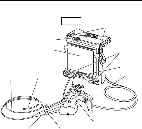
Chapter 2 Instrument nomenclature and functions
2.1System nomenclature
Main unit
Handle
LCD monitor (covered by LCD protection sheet)
Insertion tube |
Angulation section |
|
Bend stopper |
Insertion tube holder |
Strap holder
Strap holder
Front panel
Universal cable
Control unit
11
Chapter 2 Instrument nomenclature and functions
Shoulder strap
Insertion tube wrap belt
12
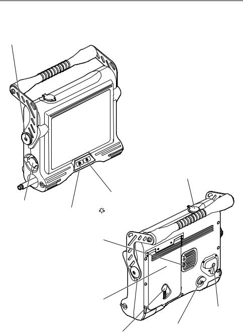
Chapter 2 Instrument nomenclature and functions
2.2Main unit nomenclature and functions
Control unit holder
Video connector cap
POWER button (  )
)
AC adapter |
LIGHT button ( |
|
) |
connector cap |
|
||
|
|||
|
Tripod screw thread |
||
Battery cover
Lock release button
Scope handset holder
Lock release lever
13
Chapter 2 Instrument nomenclature and functions
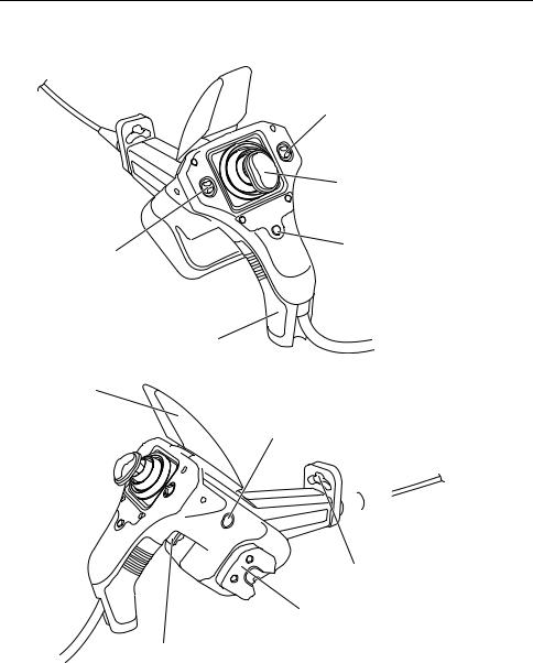
2.3Control unit nomenclature and functions
|
[ZOOM] lever |
|
Zooming the image/Menu selection/ |
|
Retrieved image selection |
|
[ANGLE] joystick |
|
Angulation operation |
[BRT] lever |
[VIEW/MENU] button |
Adjusting the brightness/ |
Retrieve screen display/ |
Menu selection/ |
Menu display |
Retrieved image selection |
|
|
Grip |
Joystick guard
[FRZ/REC] button (two locations; left and right) Freeze/record observed image/live image display
 Insertion tube holder
Hole to hold insertion tube
Secures the insertion tube
Hanger
To hang the control unit
on the main unit
[ANGLE LOCK] lever
To lock the angulation operation
14
Chapter 2 Instrument nomenclature and functions
Side view mirror adapter: 6-mm type (optional)
Objective lens |
Mirror |
Product abbreviation (50S V7X2)
Illumination Nut
Side view mirror adapter lock groove
NOTE
•The insertion tube can temporarily be fixed on the control unit by inserting it into the insertion tube holder hole.
•The insertion tube holder can be rotated or removed.
15
Chapter 3 Preparation and inspection before observation
CAUTION
•Be sure to finish the preparation and inspection work described below before use. If any irregularity is suspected, do not use the instrument but see “Chapter 8 Troubleshooting” (page 75) to solve the problem. If irregularity is still suspected, contact Olympus. Damage or irregularity may compromise the correct functioning of the instrument and may result in more severe damage to the examined subject.
•Inspections are not only required before use, but should be conducted periodically.
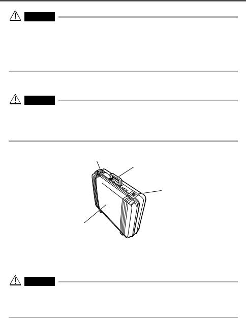
3.1Transportation of the case
CAUTION
•Before transporting the case, inspect the exterior parts handles and latch of the case for irregularities such as damage and loosening.
•Use only the designated case. Failure to do so may cause damage or malfunction of the insertion tube and/or main unit.
Latch
Handle
Latch
Top cover
When using the handle
1 Ensure that the latch is closed firmly before lifting the case.
CAUTION
•Never move the equipment around by the insertion tube or cables.
•If the latch is not completely closed, the top cover may open accidentally when the case is lifted.
•Do not kick the case or move it with your feet.
16
Chapter 3 Preparation and inspection before observation
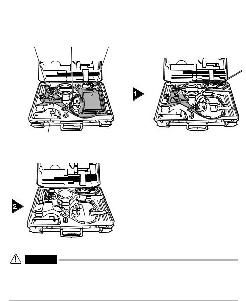
Taking the instrument out of the case
Remove the equipment in the order of: Main unit → Insertion tube →
Control unit.
Control unit |
Insertion tube |
Main unit |
|
Universal cable |
|
|
|
|
|
||||
|
|
|
Remove the main unit. |
|||||||
|
|
|
||||||||
|
|
|
|
|
|
|
|
|
|
|
|
|
|
|
|
|
|
|
|
|
|
|
|
|
|
|
|
|
|
|
|
|
|
|
|
|
|
|
|
|
|
|
|
|
|
|
|
|
|
|
|
|
|
|
Remove the control unit and insertion tube.
WARNING
•Fully open the top cover when removing the main unit from the case. If the cover is not fully open, it can close unexpectedly and pinch your hand or cables.
•Never use the main unit while it is accommodated inside the case. If the top cover of the case is left open, it may close unexpectedly and pinch your hand or a cable.
17

Chapter 3 Preparation and inspection before observation
CAUTION
•Place the case on a level surface so it is stable.
•To open the top cover of the case, release the latch on the front of the case.
•Do not pull the insertion tube with excessive force when taking it out of the cushioned slot. Otherwise, the insertion tube may be damaged.
•When taking the control unit or main unit out of the case, never hold them by the insertion tube or universal cable. It may damage the instrument.
•Check if the insertion tube, battery cover, video connector cap and adapter connector cap are kept clean. Wipe off with a clean, soft cloth if dirt or a foreign substance is attached.
•Check the insertion tube, battery cover, video connector cap and adapter connector cap if cuts or gaps are not available.
18
Chapter 3 Preparation and inspection before observation
3.2Setting up the main unit
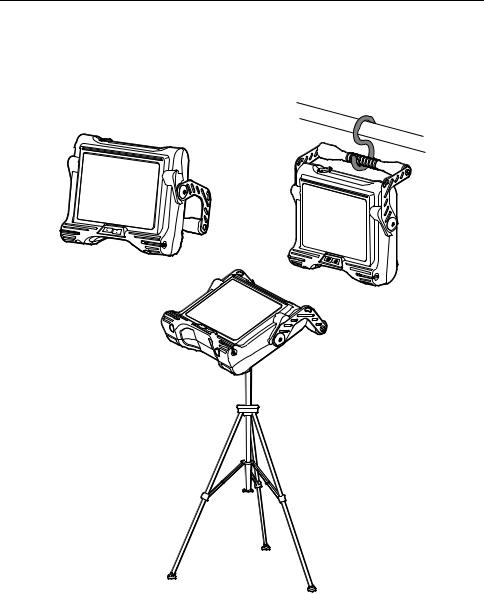
1The main unit can be used in any one of the three setup configurations shown below.
Hang it from Use the handle the handle
as a stand
Put it on a tripod
19
Chapter 3 Preparation and inspection before observation
CAUTION
•Place the main unit on a level surface so it is stable. The main unit can tip over if it is not stable.
•Do not place the main unit in overhead location. Doing so may result in the main unit falling and being damaged.
•When suspending the base unit while using it, hook the handle someplace that can support its weight and where there is no danger of it falling.
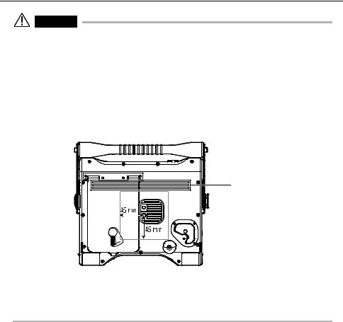
•When mounting the tripod to the main unit, install it so the tripod platform does not run up on the protrusion on the rear of the main unit. Affixing the tripod with the platform installed at an angle can cause the main unit to fall off. You can use a platform with a size that is less than 45 mm from the center of the tripod screw.
Protrusion
•Setup the tripod on level ground. Setting the tripod up on a slope or uneven ground is dangerous because it may fall over.
•Be careful not to accidently move the lock release lever on the battery cover and open it when handling the main unit.
20
Chapter 3 Preparation and inspection before observation
Using the handle
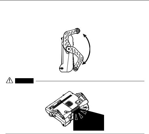
The handle can be lowered from its storage position and freely adjusted within the range shown in the illustration below. When using the handle as a stand, you can adjust the angle for easy viewing.
CAUTION
• Take care not to pinch your hand or other objects when moving the handle.
21
Chapter 3 Preparation and inspection before observation
3.3Preparing the power supply
WARNING
•Do not bend, pull, twist, crush or apply excessive force to the power cord of the AC adapter. Otherwise, a break in the power cord wires may cause a fire or electric shock.
•Ensure that the power cord is normal before connecting it. Using a power cord with irregularities may result in an electric shock.
•Be careful not to injury yourself when replacing the battery.
CAUTION
•Be careful not to accidentally drop the battery during replacement.
•Before using the battery, read the dangers, warnings and cautions in “Handling of the battery” under “Important Information – Please Read Before Use” on (page 7).
•The battery indicator flashes when a battery is continuously used under low-voltage conditions. In such case immediately turn off the power of the main unit or connect the AC adapter. If continuously used without any action the power will be automatically turned off which may cause malfunction.
•Do not remove AC adapter or battery while the system is running. It may cause malfunction.
Supplying power from the battery
1
2
3
Check to make sure that main unit power is turned off.
Return the handle to its storage position.
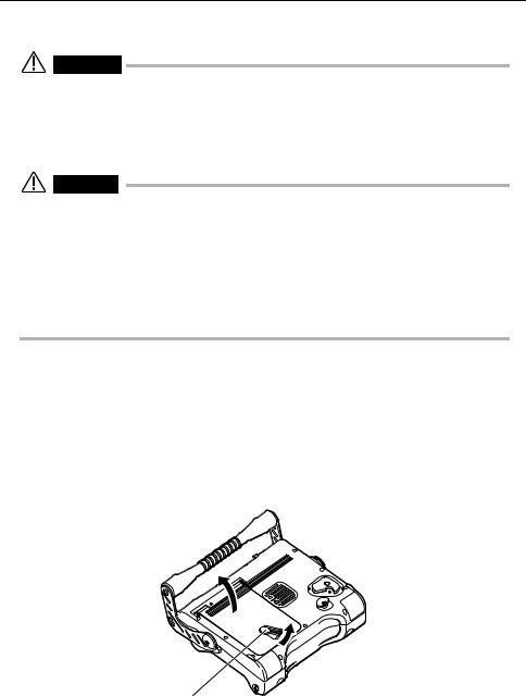
Move the lock release lever on the battery cover as shown in the figure below to open the battery cover.
Lock release lever
22

Chapter 3 Preparation and inspection before observation
4 Insert the battery so that the ribbon passes under it. This is so you can pull the ribbon to remove the battery.
Ribbon
CAUTION
•When loading the battery, check to make sure the main unit’s battery contacts and the battery terminals are positioned correctly.
•Never try to force the battery if it does not slide in easily. Check to make sure that the battery is positioned correctly and that there is no problem with its terminals. Trying to force the battery in may cause malfunction.
5 Close the battery cover and move the lock release lever on the battery cover as shown in the figure below to lock it.
Lock release lever
NOTE
•If you are having trouble locking the battery cover, press on the cover while moving the lock release lever.
23
Chapter 3 Preparation and inspection before observation
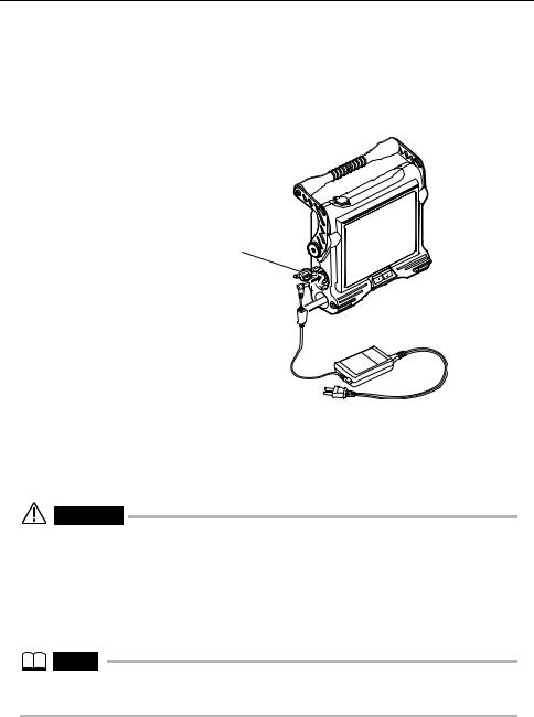
Supplying power from the AC adapter
1
2
Open the AC adapter connector cap.
Connect the AC adapter to the AC adapter connector on the main unit.
AC adapter connector cap
3 Ensure that the AC power cord is connected securely to the AC inlet of the AC power adapter.
4 Plug the AC power cord securely into a power outlet.
WARNING
•Inspect the power cord before use and check for any signs of damage. Using a power cord with irregularities may result in an electric shock.
•Uses AC power code appropriate for the standard AC power in the country that uses it.
•Never use an AC adapter other than the designated AC adapter. Otherwise, malfunction of the instrument or unexpected damage may result.
•The AC adapter is not water resistant. Never use it in the rain or in any location where it can become wet. Water creates the risk of electric shock.
NOTE
•For information about how to connect the AC adapter, see the AC adapter’s instruction manual.
24
Loading...